


minicopter
Diabolo „S“
Ord.-No. 4950
Manual
minicopter
Rheinstahlring 47
34246 Vellmar
Germany
+49 561 988 2800
info@minicopter.de
www.minicopter.de

Congratulations to your new Diabolo S, one of the fastest model helicopters. This model was
created to reach the highest possible speed under highest possible power with best possible aerodynamic. The Diabolo S was designed without any comromise. It is extremly small,
the fuselage section has a shape like a symmetrical airfoil to minimize drag. To mount all the
mechanics and electronics into it you need some informations what is the intention of this manual. For the basic mechnical assembly you can also use the classical Diabolo manual. The
assembling technic of the Diabolo and Diabolo S mechanics are very similar. Only the parts
are a little bit different, so there is a part-no. translator attached. This manual was created
to show the special differences of this model including some assembling and justation hints.
Have fun with the assembly and if you have any questions you can send us an e-mail to
info@minicopter.de . We wish you also a lot of fun with the fl ights of your Diabolo S!
Recommended equipment:
Motor: X-Nova 4535-510 4+4 YY1.6 Pyro 850-50L Pyro 750-50/56 BE
Controller: Kosmik 200 Cool14s YGE320HV16s
Servos: Servos like BLS451 with max 18mm from mounting surface to upside servo arm
FBL-System: BD3-(S)X, AC-3X, V-Stabi
Receiver: 2,4GHz
Flight battery: 2x7s/4400/>60C -2x8s/3850/>60C
Receiver battery: 2s/1600-1800/25-30C (alternativly combine with Kosmik BEC on 8,0V)
Rotorblades: DH691 or DH711
These are components we have tested and we can recommend. Of course you can use
compinents from other manufacturers too, but you must decide individually if they are ok
for the Diabolo S or not.

Maintenance and Security
A radio controlled model helicopter and a speed helicopter especially is not a toy. A mistake
can result in serious accidents and injuries. So keep the following rules always in your mind:
1- Start always with an Idle Up 1 of about 1600 rpm and switch up to Idle Up 2 fi rst when the
model is at least 10 metres high and 20 metres away.
2- Fly high speed passes always with a minimum distance of 50 metres / 150 ft to you. No person should be between you and the model (f.e. modelers with cameras).
3- Keep a minimum fl ight height of 30 metres. Nore that reaching extreme speeds you reach
at the blades tips the transsonic area which can result in particulary stalls on the airfoil. To rescue the model you need a minimum height to react and start actions to save the model.
4- Fly with discipline. Do not fl y more passes that you have calculated before. Do never fl y
deep and closed to enlarge the impressions of spectators.
5- Do not fl y with crosswind that press the model in your direction. All aerodynamic bodies,
also the Diabolo S are sensitive against crosswinds and can move cross to you more than you
have expected.
6- Do not go over your personal limit. High speed fl ight needs a lot of training and experience
that you must learn fi rst. With increasing speed you must calibrate your FBL system perhaps
different, modify parametres like headspeed and pitch.
7- Do not fl y faster and only so far away how your eyes allow this. The model can climb after a
pass very fast heights and distances that are diffi cult to observe. So be careful.
8- The most important rule: Do never start if you are not absolutely sure that everything is ok!
Maintenance: The Diabolo S was designed for a high standard reliability and durability. But
that does not mean that you must not do any maintenance. After each fl ight you should do a
check of ALL mechanical parts. Look for loose screws, cables. Check the bearings, gears, all
electric connections, ball joints, antennas.
The second stage gear must be lubricated. Calculate that after each fl ight you must add two or
three drops from the oil bottle that is in the kit. In each casee it may never run dry. Avoid to fl y
in a dusty environment and if you do that then climb up fats from the ground to minimize dust
in the body.
Pitch adjustments: -6°/+5°/+16°
Idle up 1: 1600 rpm Idle up 2: 2200 rpm Idle up 3: Max rpm
Because we cannot control what a modeler is doing with the model we cannot give any warranty.
Vellmar, in February 2014

Part-No. translator Diabolo - Diabolo S
The following parts are similar between both models but not the same. So use this tarnslator to fi nd the right part no. if you need any spare.
D1 upper left side frame D258
D2 upper right frame D259
D14 mainshaft D220
D16 lower mainshaft bearing plate D272
D17 Upper bearings plate D271
D70 First stage bearing D243
D71 Mainshaft bearing D230
D13 Main gear wheel D274
D15 distance bush mainshaft D224
048 washer shim 0,1mm D231
033 washer shim 0,2mm D232
D7 gear wheel fi rst stage D7a
D5 fi rst stage distance bush D195
D4 main gear pinion D275
D21 tailboom D280
D46 tail pulley D249
D43 tail gear housing D246
068 tailshaft bearing D247
D47 distance shim D250
044 washer shim 0,1mm D46
D45 tailrotor shaft D245
D18 roll servo holder D273
D28 vertical U-Profi le D284
D25 belt tensioner arm D261
D34 shock absorber D262
902 landing skids pair D281
D20 distances elevator servo D270
D89 elevator servo screws D83
D23 rear tailservo mounting block D283
D50 swashplate D226
D58 conic distance bush swashplate D233
D104 screw for D58 D102
D91 screw for distance bush D90
D32 distance bush for swash holder D244
D90 screw for D32 D88
D52 mainrotor hub D229
521 feather spindle D235
586 damping insert D236
047 washer shim 0.5mm 757
071 blade grip bearing D238
509 inner grip bush D239
100 thrust bearing D237
052 washer shim feather spindle D242
034 spindle screw D234

538 mainblade grip D240
593 swash driver distance bush D241
110 tailrotor hub D255
979 conic ring D257
1471 tailslider D256
D49 tail bellcrank D264
347 tailslider guidance bush D288
D155 battery plate D269
- Battery plate stopping block D279
The following parts are new and not in the normal Diabolo manual:
D191 support bearing block
D263 holder for D262
D265 L-Profi le left
D266 L-Profi le right
D267 front skid holder
D268 rear skid holder
D276 canopy connector 3.5mm
D277 canopy connector 4mm
D278 triangle plate CF
D285 maingear lubrication oil 60ml
D286 mounting bush Kosmik
D287 battery tray stopping block

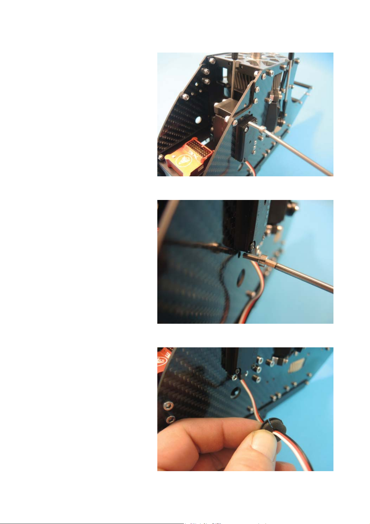
This is the mechanic in
delivery condition.
Remove the battery plate for
the rear fl ight battery.
Remove the roller. Later the
roll servo cables will be placed
between the spacers under the
roller.

Remove the rear tail servo
holder. Do not lose the screw.
Keep both parts together.
Open bag 7 and sort the parts
on the table.
Start with mounting the fl y-
barless system. We recommend to mount it directly on
the U-profi le. On the picture
we mount a Bavarian Demon
HC3X.

Mount the ball joints on the
servo arms using for each
arm a hex lense screw M3x16
D103, two 3mm washers 002
and a M3 lock nut 008. Attach
two rods D54 with four ball
joints D72.
The overall length of both roll
servo rods should be 103 mm
about.
Insert the left roll servo into the
frame. Look that the cable is
going downwards.

Fix the servo with four hex
screws M3x12 D84 and
washers 002 using Loctite
on the screw thread. Do not
overtighten the screws. Then
the thin bushes in the rubber
blocks would be compressed.
Now mount the right roll servo
in the same way.
Look that both cables are
placed as shown.

The screws are easier to
mount if you look before attaching the screws into the hole
to what direction the thread is
going about. The rubber blocks
are elastic so during mount it
is not always guaranteed that
the thread is also in the center
of the bush. After attaching all
screws it will be centered.
Mount the screws using Loctite
on the thread.
Two plastic blocks must be
mounted on the elevator servo
with four hex screw D84 and
washers 002 (use no Loctite!).
Note that the block D270 on
the cable side is 2 mm higher
than the block D299 on the
other side.

Blocks in mounted condition.
Length of elevator servo arm
should be 102.5mm.
The small triangle carbon part
makes it a little bit diffi cult to
insert the servo but a servo like
Futaba BLS451 defi netly fi ts. If
you have problems then loose
for the servo mount the three
lense screws of the triangle a
little bit and tighten them again
when the servo is placed.
Mount the upper block with
two hex screw M3x10 D83 (no
Loctite!). Do not overtight the
threads in the blocks.
For the lower block use two
hex screws M3x8 D82.
Cut the rubber grommet D80
with a knife and insert the servo cable. Then insert the servo
connector into the hole of the
CF frame and fi nally press the
grommet in.

All servo cables should be under the mechanic right now.
Now mount the roller block.
The best is to attach fi rst the
screws and from inside the
spacers. Then add the roll
servo cables between and add
Loctite on the screws threads.
Then add the roller block.
During tightening have an eye
on it that the cables are not
squeezed beteen the contact
planes of the parts. The result (with a contacted impulse
cable) could be sudden movements of the servo arms.
For better identifi cation when
you plug in the connectors in
the fl ybarless system it makes
sense to add a „R“ and „L“ on
the roll servo cables.

Install the cables as shown on
the pic.
The tail servo holders should
be mounted with four hex
screws M3x12 D84 and
washers 002 using Loctite.
Note that the block with the
countersunk hole is placed on
the cable side. The fuselage is
very narrow at this area so a
countersunk screw is necessary there.
Insert the tailservo in the
shown way. A MKS 980 servo
just fi ts into the frame, also
of course the smaller Futaba
BLS 251/256. On the servo
the arm must be attached with
a screw using Loctite. If you
are not sure if the arm is in the
right position on the toothed
shaft then do not mount the
two screws that fi x the servo
mounts on the frame. Tighten
them after FBL calibration, but
do not forget it!

If you are sure the servo arm is
in correct position then add the
countersunk screw M3x12 471
on the rear servo block using
Loctite.
Accordingly mount the front
block with a hex screw M3x14
D85 using Loctite.
Now plug in the connectors
into the FBL system.
Important: After you have
mounted all plugs in the system fi x them with hot glue that
they cannot come out under
vibrations. This suggestion is
independent from the type of
used fl ybarless system.

Press all cable length that is
not necessary under the Uprofi le. There is a lot of space
for cables and the upper side
looks very nice without unnecessary cables.
Attach a piece of double sided
foam (about 3mm or 1/8“) on
the reiceiver.
Place the receiver, here a
Futaba 6303SB, as shown. If
your receiver is bigger you fi nd
alternative places under the Uprofi le, outside the frame or on
the additional gyro platform.

Add now the swashplate body
D226 on the justation help
D289 on the mainshaft.
Mount the left servo rod using
a hex lense screw M3x12
D102 and a conic spacer
D233. For maximum safety
here add righ Loctite on BOTH
threads and remove unnecessary Loctite at once.
The swash plate guidance is
made from a hex screw M3x25
D90, a brass spacer D55 and
a conic bush D233. Add also
with rich Loctite on both ends.

Check that brass bush is moving free in the guidance after
tightening the screw.
Add the swash guidance D32
using two hex screws M3x25
D90 and two spacers D244
using Loctite.
Have a fi nal check that the
swash guidance is parallel to
the mainshaft.

Now prepare the rotorhead.
Open bag 8 and sort the parts
on the table. The big washer
shims are not necessary and
only added for individual tightening of the spindle.
The length of the linkages is
about 62 mm.
Attach the linkages on the
arms with two hex lense
screws M3x12 D102 using
Loctite. Note that the joint with
the left thread (marked with a
small ring) is upwards (mounted on the blade arm).

Add the two joints bolts M3x4
076 on the swashplate using
Loctite.
Mount the swashdriver arms
D65 as shown in the pic using
Loctite. The screw for mounting on the hub is a hex lense
M3x10 D101 with a washer
3x6x0.2 455, the outer one is
a M3x12 D102 that is screwed
into the bush D241. Finally the
joint 385 is fi xed with a cross
screw M2.5x12 509 (no Loctite!). Finally mount both units
on the hub using Loctite.
Put the rotorhead on the
mainshaft. Do not forget to
loose the two black M3 screws
in the hub before.

Fix the rotorhead with a special
M4 jesus bolt M4 D78.
Tighten both black screws
M3x12 D119 using Loctite.
After tightening you can press
the links 385on the joint bolts
076.
Mount the linkages on the
swashplate using hex lense
screws M3x12 D102 using
Loctite.

Now the mechanic should be
in the shown condition. We
continue with the motor mount.
Open bag 6 and sort the
screws on the table. Dependend from the motor type
(some motors need very short
M4 screws there are two
lengths included. If possible
use always the longer ones.
Mount the motor using four M4
hex lense screws- Note that
the rounded contour of the
motor carrier is showing to the
front.

Attach the pinion on the motor shaft. The delivered pinion
is normally 20T with 6mm
shaft. There are also pinions
with 8mm hole available, also
pinions from 15-22T with 6mm
shaft and from 18-22T with
8mm shaft. If the motor shaft
has no fl at spot then add one
at the end of the shaft (mark
the position before, pinion
should be 0.5-1mm away from
the lower motor carrier plane).
Tighten now the grub screws
M4x5 D35, beginning with the
one on the fl at spot.
Now install the motor using
four hex screws M3x8 and
washers 3mm 002 using Loctite. The plastic gear wheel is a
high temperature high tech polymer that is uncritical against
any heat. You should feel a
small but noticable play between pinion and gear wheel.
For 21 or 22T pinions you must
fi le the long holes 0.5 or 1mm
to the front using a needle fi le.
During mount press the motor
down that it is really vertical.

Now the mechanic should be
in this condition.
Remove from the front end of
the tailboom with a fl at fi le a
part of the anodizing as shown
on the picture. This is necessary to eliminate electric noise
from the belt.
Now press the boom carefully
in.

Look that all cables are between boom and U-profi le and
that no cable will be hurt when
you insert the boom into the
front clamp.
Adjust the boom that it is some
millimetres out of the front
clamp.
Now insert provisorically the
brackets into the tail housing to
fi nd the right orientation of the
boom for tightening.
Remove the rubber band.
After pulling the belt thru the
boom with a long wire with
bended end put on the tailrotor
housing that the screws of the
brackets fi t fully in the slots of
the boom. Lokk in the housing
that the brackets are vertical. If
not yet then open the screws a
bit more.
Insert the tail pulley into the
belt from the side that has no
washer yet and put it into the
tail housing.

Now put the tailshaft D245 in
and look that the belt is positioned completey on the pulley.
Tighten the belt pulling the
tailboom outwards. Note that
on the Diabolo S there is not
much tail thrust necessary and
on the other hand the power
lost of a too much tightened
belt should be as low as possible. So do not tighten the belt
too much. Pull with about 2
kgs / 4lb. After fi nding the best
position tighten the screws in
the boom clamps (Loctite!) and
then tighten both lower right
clamp screws.
Finally attach the tail servo rod
in the usual way that is shown
in the Diabolo manual. Note
that the length of the rod is
here some mm longer than in
the Diabolo.

Fuselage mount
Pull the tailbelt thru the boom
(a wire with a bended end
works best). Remove with a
fi le or sanspaper the black
anodizing a little bit at the front
end so that there is an electric
contact between frame and
boom. Insert the boom with the
clamp into the frame.
Attach the screws for the tailboom clamps with Loctite 243.
Tighten the lower right screws
fi rst when you have tightened
the long screw D93 in the
boom clamps.
Now press the boom careful in
the fuselage tail. Look that the
foam on the boom will newhere be damaged. This foam is
necessary to eliminate noisy
resonance vibrations from
the fuselage. Note that the fi t
between fuselage and mechanic was factory tested and so
you should use no force for the
mount.
The lower left mounting screw
must correspond with this hole.
In the pics only the preassembled mechanic is shown. Of
course you must fi nish the me-
chanic fi rst before you insert it.
Also it is highly recommended
to make the fi rst tests and jus-
tations with naked mechanic.
If the holes are concentric then
use for the mount a hex screw
M3x12 and a lock nut M3.
Look that all electric cables
are free and no mechnical
part is touching the fuselage.
Start as shown with the lower
left screw. Do not tighten the
screw too much. Note that there is wood between that could
be unneccesary compressed.
Now do the same procedure
with the lower right screw.

Then attach the upper right
screw. To get the holes concentric you must press now the
end of the boom to the upper
end of the fuselage (compress
the foam).
Finally mount the upper left
screw.
When you mount now the
landing bows be careful that
you do not scratch the surface
of the fuselage. To minimize
this risk press fi rst the wire
into the front hole. Look before
that holes in the fuselage and
landing bow holder under the
mechanic are corresponding. If
not then open the four fuselage
mounting screws again and
press the fuselage a little bit in
teh right direction. Alternatively
you can widen the hole with a
thin needle fi le.

Now turn carefully the wire
and look that you do not make
scratches on the fuselage. A
bit of masking tape can help to
avoid this.
Now, holding the front end in,
press the rear end into the
slot. Take care that the hole
in the fuselage and in the rear
skid holder of the mechanic
are corresponding. Press the
skid as long in as the radius
is reached. If you look from
inside the skid should end
exactly at the inner edge of the
skid holder. If not then move it
as long if this is the case.
Then tighten the rear grub
screws using Loctite 243 with
a long 2mm hex driver. Take
care that the landing bow wire
is not coming out of the block.
The batteries could be damaged from it.

Tighten now the front screws
using also Loctite 243.
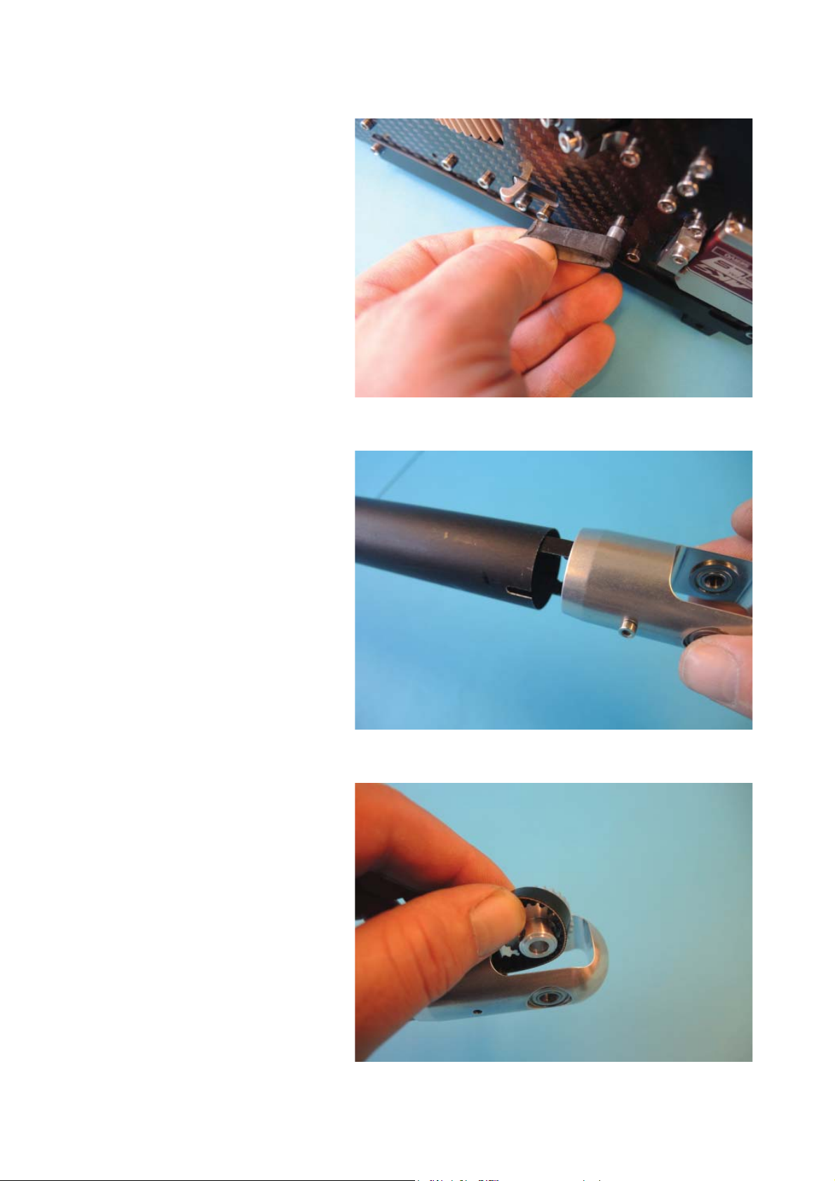
The tailgear mount is different
to the normal Diabolo because
you have no access to the
boom clamps. So you must
tighten the mechanic correct
before you insert it into the
fuselage (we have done this
for you). For easier mount now
remove the rubber ring from
the belt tensioner. Take care
that the belt is in the correct
orientation (90° to the right
from parallel belt position).
Note that the tailgear must
be ready assembled with
bellcrank and fi n (not as
shown). The tightening blocks
D43a must be mounted and
the screws attached with Loctite 243. Now press the gear
housing on and look that you
feel an and (where the boom
has contact with the end of the
inner housing).

Tighten the screws, look inside
that they are parallel together
and that the tail fi n is parallel to
the mainrotor shaft.
To mount the belt wheel the
right washer shim of the wheel
(on the side without grub
holes) must be removed. Then
put it in over the belt (Careful!
Do not damage the belt).
Add the washer shim (side with
the cone to the left/belt side).
Have a look that you use the
correct holes and not the holes
that are used from the other
washer shim.

Then tighten the washer shim
using three lense screws M3x6
D99 and Loctite.
Now add the small special
washer that fi ts exactly in your
tail housing. Do not loose it.
It was made induvidually. To
be on the safe side you can
measure the shim with a digital
caliper and if you later would
loose it we can turn a new one
for you that fi ts perfect too.
Then add the tailshaft and
tighten it with two grub screws
M4x4 #573. The shaft end is
corresponding with the outer
end of the left bearing.
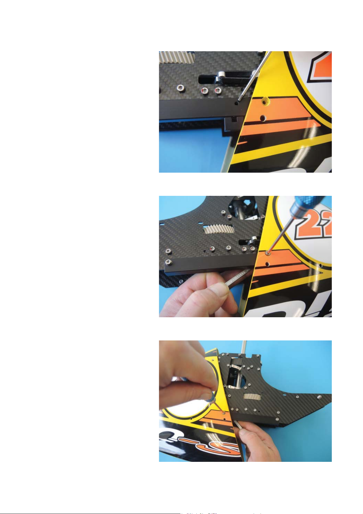
For mounting the front canopy
widen the upper rear end and
move the front part over the
mechanic. Look that you do
not hurt any cable.
For mounting the front part
the slot between the fuselage
part must be ALWAYS parallel
and all the fi ve connector pairs
must correspond together.
Note that we have spent many
time that it fi ts perfect, so you
need also time and patience to
mount it (removing it in panic
situations is much faster).
If you would ever damage a
spring cage of a male connector you can use a normal
4mm connector #1964 and
must simply remove the spring
with your thumb nails and then
press it carefully onto the front
bolt.

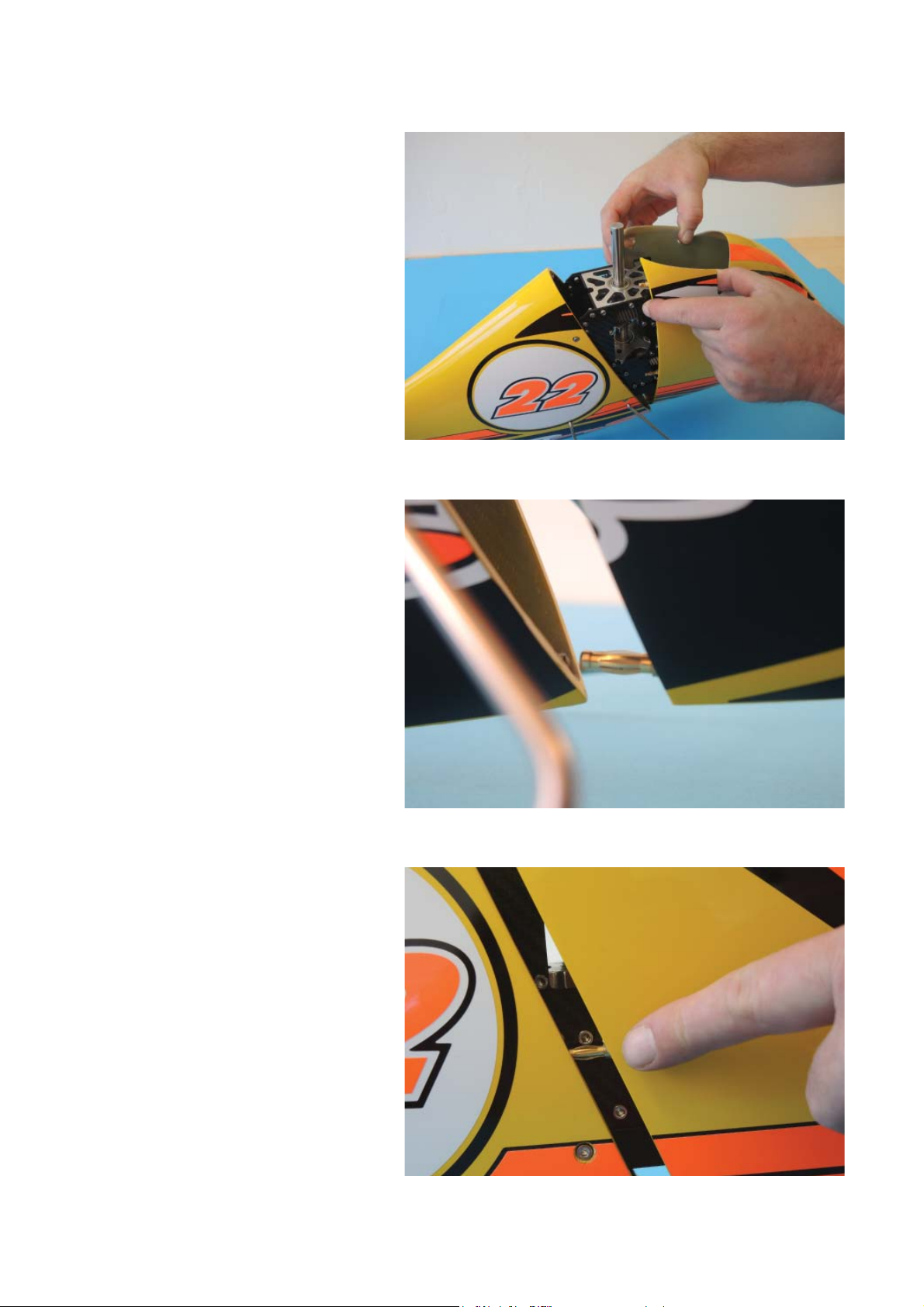
It is necessary for high speed
fl ight to attach about 6“/15cm
of clear tape on each side
before each fl ight. During turns
with zero forward speed the
front fuselage could else be
opened a little bit what is reducing speed.
The slot between the two fuselages parts should be nearly
zero now.
For easy removal of the tape
turn the lower 5mm about that
they are free from the fuselage. So in urgent situations the
stripes can be removed within
one second each.
 Loading...