

Minicom DX DX 432, DXU Operating Manual
DX System
Operating Guide
Supported by:
Technology Corporation
International HQ
Jerusalem, Israel
Tel: + 972 2 535 9666
minicom@minicom.com
www.minicom.com Customer support - support@minicom.com
© Copyright Minicom Advanced Systems Ltd. 5UM20121 V1.3 9/04
North American HQ
Linden, New Jersey
Tel: + 1 908 4862100
info.usa@minicom.com
®
Rackit
® Technology Corporation
274 Madison Avenue, New York, NY 10016
Tel: (212) 679-0050 • Fax: (212) 679-0040
1.800.636.3434
European HQ
Dübendorf, Switzerland
Tel: + 41 1 823 8000
info.europe@minicom.com
www.RackitTechnology.com
Italy
Rome
Tel: + 39 06 8209 7902
info.italy@minicom.com

DX SYSTEM
Table of Contents
Getting started .............................................................................. 2
1. The initial cascade wizard..................................................................... 2
2. Logging in .............................................................................................. 4
Configuring the DX system.......................................................... 5
3. Configuring individual output ports..................................................... 6
4. Configuring individual input ports ....................................................... 8
Cascading the DX system ............................................................ 9
5. Adding / editing secondary level KVM devices................................... 9
6. The General Settings window............................................................. 14
Creating Users and Groups ....................................................... 16
7. Defining Group access rights............................................................. 18
Arranging devices ...................................................................... 21
8. The Servers window ............................................................................ 21
9. Creating a new folder .......................................................................... 22
10. Saving changes ................................................................................... 22
11. Deleting and renaming folders ........................................................... 22
12. Adding devices to a folder.................................................................. 23
13. Viewing the servers/devices............................................................... 23
Operating the DX system ........................................................... 24
14. Viewing devices ................................................................................... 24
15. Adjusting the picture quality .............................................................. 24
16. Power on/off reboot............................................................................. 24
17. Connect - Private ................................................................................. 25
18. Disconnect User .................................................................................. 25
Updating the DX Central............................................................. 26
19. System requirements for the DX Central Update software .............. 26
20. Running the DX Central Update software.......................................... 26
21. Updating the DX User unit and X-RICCS ........................................... 27
22. Verifying the X-RICC version numbers.............................................. 28
23. Updating the firmware......................................................................... 29
24. Viewing the log .................................................................................... 29
25. Resetting the DX Central..................................................................... 30
USB / SUN Combo keys ............................................................. 31
Technical specifications ............................................................ 32
Appendix A: Pin assignments ................................................... 34
1
OPERATING GUIDE
Getting started
1. The initial cascade wizard
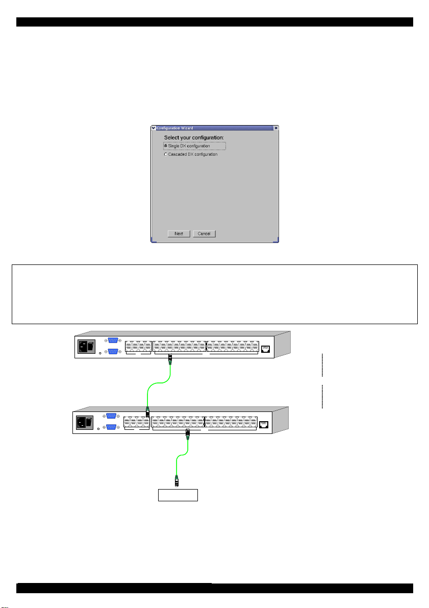
Once the system is connected and powered on, the Configuration Wizard box appears
on the screen of the DX User. See Figure 1.
Figure 1 The Configuration Wizard box
Important!
To define the Slave (second level cascade – see diagram below), you must physically
connect a DX User unit to the Slave. The initial cascade wizard appears and the
procedure outlined here must be followed.
www.minicom.com
POWER
100-250 VAC 50/60 Hz
SERVICEI
0
SERIAL
1234
18 19 2017
6785
1234
USER
22 23 2421
5678
26 27 2825
9101112
SERVER
30 31 3229
13 14 15 16
ETHERNET
DX Central
- Primary level
Cascade
www.minicom.com
POWER
100-250 VAC 50/60 Hz
18 19 2017
SERVICE
SERIAL
6785
1234
USER
1234
I
0
22 23 2421
5678
26 27 2825
9101112
SERVER
30 31 3229
13 14 15 16
ETHERNET
Server
DX Central
- Secondary level
Figure 2 Cascaded DX Centrals
1. Where the DX User connects to cascaded DX Central units check Cascaded DX
configuration. Otherwise click Single DX configuration.
2
DX SYSTEM
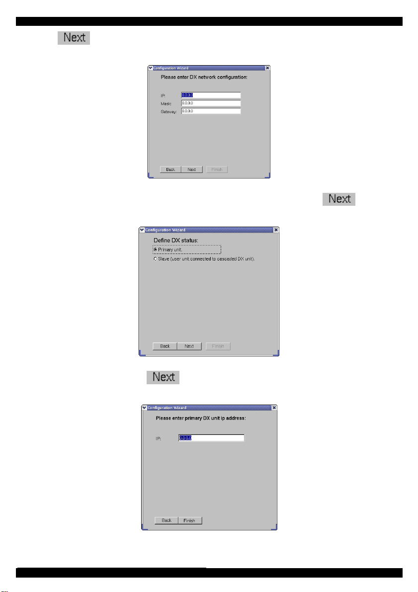
2. Click . If the DX system is cascaded the DX Network Configuration box
appears. See Figure 3.
Figure 3 The DX Network Configuration box
3. Type in the network parameters for this DX Central unit and click . The
Define DX status box appears. See Figure 4.
Figure 4 The Define DX status box
4. Select the status and click . When defining a Slave unit the following box
appears.
Figure 5 Primary DX unit IP address box
5. Type in the IP address of the Primary DX Central unit.
3
OPERATING GUIDE
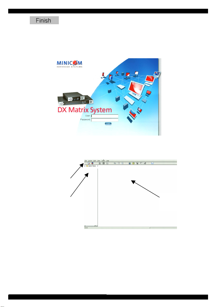
6. Click . The Login screen appears see below.
2. Logging in
Once the system is connected and powered on, the Login screen appears on the monitor
of each DX User. See Figure 6.
Figure 6 The Login screen
Type the default username ‘admin’ and password ‘admin’. The Main screen appears.
See Figure 7. The screen initially shows no devices. The system must be configured.
Toolbar icons
Created folders
appear here
Devices
appear
here
Figure 7 The Main screen
4
DX SYSTEM
Configuring the DX system
You must configure the devices connected to the DX system.
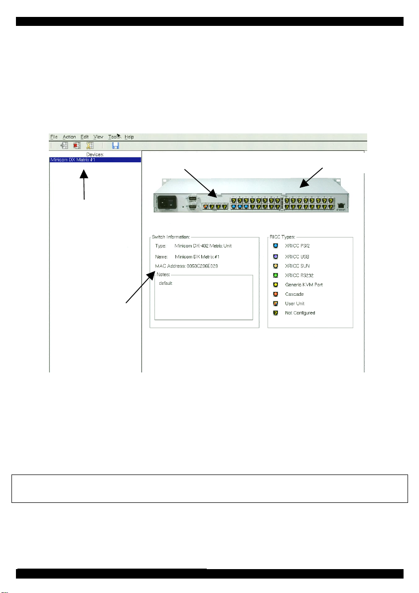
From the View menu choose DX System Configuration. The DX System
Configuration window appears. See Figure 8.
Output ports to devicesInput ports from DX Users
List of DX Central
units and KVM
switches
Information of
currently selected
unit
Figure 8 The DX System Configuration window
You can view the rear ports of the DX Central units and KVM switches attached to the
system.
To view a unit:
From the list on the left, click a unit. A picture of the unit’s rear panel ports appears.
The ports are color coded as outlined by the list of RICC Types.
Note! Place the mouse cursor over a button. A tool tip appears showing the name of the
device connected to that port.
5
OPERATING GUIDE
3. Configuring individual output ports
Configure individual devices connected to the DX Central output ports.
To configure individual output ports:
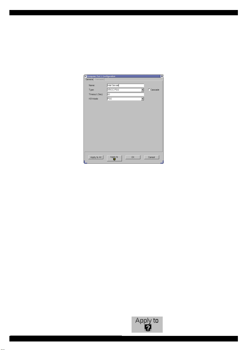
1. In the DX System Configuration window click an output port on the picture of the
switch. The Computer Port Configuration box appears, see Figure 9.
Figure 9 The Computer Port Configuration box
The General tab elements
Name – Type a name for the connected device. This name appears below the device in
the Servers and devices window.
Type – Select the appropriate X-RICC connected to the port.
Note! When selecting an X-RICC RS232 type, you must also input the terminal
settings.
Timeout – Type a timeout period after which another User can take control of the
device. By default it is 60 seconds.
KB Mode – Select the appropriate keyboard mode. By default the keyboard mode is
set to PS for Intel based computers.
For the other systems set the KB mode as follows:
• U1 for HP UX
• U2 for Alpha UNIX, SGI, Open VMS
• U3 for IBM AIX
To apply the changes to the selected port click
6
.

DX SYSTEM
To apply the changes to all output ports click .
The Cascade box elements
When you cascade the DX system, click the Cascade checkbox to un-gray the Cascade
tab.
Click the Cascade tab. The Cascade box appears see Figure 10.
Figure 10 The Cascade box
Device name – Select the secondary level cascaded switch from the Drop-down list.
Input Port No – If the secondary level KVM switch is a DX Central, from the Drop-
down list select the input port number of the secondary level DX Central.
To apply the changes to the selected port click
To apply the changes to all output ports click
7
.
.
OPERATING GUIDE
4. Configuring individual input ports
Although the input ports in the DX Management console appear to be un-configured,
the DX system does recognize the connected DX Users. Configure the input ports to
display the DX User icon.
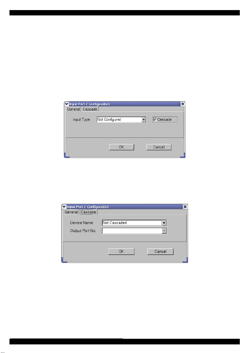
To configure the input ports:
1. In the DX System Configuration window click an input port on the picture of the
switch. The Configuration box appears see Figure 11.
2. From the Drop-down box choose the DX User unit.
Figure 11 The Configuration box
Cascaded DX Central units
3. When the DX Central is a secondary level cascaded unit, click the Cascade
checkbox to un-gray the Cascade tab. Click the Cascade tab. The Cascade box
appears see Figure 12,
Figure 12 Cascade box
Device name – Select the cascaded KVM switch from the Drop-down list.
Output Port No - From the Drop-down list select the output port number of the
primary DX Central to which the secondary level unit is connected.
8

DX SYSTEM
Cascading the DX system
When cascading DX Central units or other KVM switches, you must configure them in
the DX System Configuration window – see Figure 8. Where the switch is not
cascaded you can ignore this section and go to page 14.
5. Adding / editing secondary level KVM devices
The table below explains the DX Management console Toolbar buttons.
Button Function
Add unit
Delete unit
Edit unit
To add a new KVM switch:
Click
9
. The Add New KVM Device box appears. See Figure 13.
Figure 13 The Add New KVM Device box

OPERATING GUIDE
The General tab elements
Name – Type a name for the new device.
Type – From the Drop-down list select the new device type. If it doesn’t appear in the
list, it can be added (explained below - To add new…).
Users / Servers – Displays the maximum number of users and servers for the device
Description – type a description of the device. This will appear in the Description box
in the DX System Configuration window. See Figure 8.
MAC Address – Type in the MAC address of the KVM device.
To add new…- To add a type of device that does not appear in the Type Drop-down
menu:
1. Click
. The Add New Device Type box appears. See Figure 14.
Figure 14 The Add New Device Type box
2. Type a name for the new device and select the number of input and output ports.
Figure 15 below illustrates input and output ports.
10
 Loading...