

Page 1
SmartRack 116 IP
User Guide
International HQ
Jerusalem, Israel
Tel: + 972 2 535 9666
minicom@minicom.com
www.minicom.com
North American HQ
Linden, NJ, USA
Tel: + 1 908 486 2100
info.usa@minicom.com
Technical support - support@minicom.com
European HQ
Dübendorf, Switzerland
Tel: + 41 44 823 8000
info.europe@minicom.com
5UM20182 V1.1 11/08
Page 2

SMARTRACK 116 IP
Table of Contents
1. Welcome......................................................................................................................4
Section I...........................................................................................5
2. Introduction.................................................................................................................5
2.1 Key features........................................................................................................................................5
2.2 Compatibility........................................................................................................................................6
3. System components....................................................................................................6
4. Hardware kit contents.................................................................................................6
5. Pre-installation guidelines...........................................................................................7
5.1 Avoiding general rack mounting problems.........................................................................................8
6. Connecting to a rack...................................................................................................8
6.1 Using the longer bracket for rack depth of 905 ~ 990mm...............................................................11
6.2 Connecting the KVM Switch 116 IP.................................................................................................12
7. The SmartRack Switch system configuration...........................................................14
7.1 The 116 switch..................................................................................................................................14
7.1.1 Connector table........................................................................................................................15
7.2 Connecting ROCs to servers............................................................................................................15
7.2.1 Connecting a ROC PS/2..........................................................................................................15
7.2.2 Connecting a ROC USB...........................................................................................................16
7.3 Connecting the CAT5 cables............................................................................................................17
7.4 Connecting to the network................................................................................................................17
7.5 Connecting the power supply...........................................................................................................17
8. Terminology..............................................................................................................17
9. Initial settings - Default IP address...........................................................................17
9.1 Static IP addresses for a number of units........................................................................................18
10. Logging into the Web interface...............................................................................20
10.1 SSL Certificate notes......................................................................................................................20
11. Network > Configuration.........................................................................................21
11.1 LAN 1...............................................................................................................................................21
11.2 KVM.net...........................................................................................................................................22
12. Network > SNMP Settings.......................................................................................22
12.1 SNMP Events table.........................................................................................................................23
13. Administration > User Settings...............................................................................25
13.1 Adding a user..................................................................................................................................26
13.2 Editing a user..................................................................................................................................26
13.3 Deleting a user................................................................................................................................26
13.4 Blocking a user................................................................................................................................26
14. Administration > Switch Configuration...................................................................27
15. Administration > User Targets................................................................................27
16. Security > Settings..................................................................................................28
17. Security > SSL Certificate.......................................................................................29
18. Maintenance > Firmware Upgrade...........................................................................30
19. Restore Factory Settings.........................................................................................30
1
Page 3

USER GUIDE
20. Saving changes and logging out.............................................................................31
21. Starting a remote session.......................................................................................31
21.1 Taking over a busy remote session................................................................................................33
21.2 The Toolbar.....................................................................................................................................33
21.3 Switching to a different server........................................................................................................34
21.4 Changing the performance settings...............................................................................................34
21.5 Adjusting the Video settings...........................................................................................................35
21.5.1 Refresh....................................................................................................................................35
21.5.2 Manual Video Adjust...............................................................................................................35
21.5.3 Auto Video Adjust...................................................................................................................36
21.6 Power cycle.....................................................................................................................................37
21.7 Keyboard key sequences...............................................................................................................37
21.8 Synchronizing mouse pointers.......................................................................................................38
21.8.1 Aligning the mice pointers......................................................................................................39
21.8.2 Calibrating mice pointers........................................................................................................39
21.8.3 Manual mice synchronization.................................................................................................39
21.9 Minicom icon menu features...........................................................................................................41
21.10 Full screen mode...........................................................................................................................42
21.11 Disconnecting the remote session...............................................................................................42
22. Troubleshooting - Safe mode..................................................................................42
22.1 Entering Safe mode........................................................................................................................43
22.2 Restoring factory defaults...............................................................................................................44
22.3 Restoring the device firmware........................................................................................................45
Section II........................................................................................46
23. Switching between computers................................................................................46
23.1 The keyboard hotkeys.....................................................................................................................46
24. The OSD...................................................................................................................46
24.1.1 Navigating the OSD................................................................................................................47
24.1.2 Selecting a computer..............................................................................................................47
24.1.3 The OSD settings (F2)............................................................................................................47
24.1.4 The General settings..............................................................................................................48
24.1.5 F7 Defaults..............................................................................................................................50
24.1.6 The Ports settings...................................................................................................................50
24.1.7 The Time settings...................................................................................................................51
24.1.8 Users.......................................................................................................................................52
24.1.9 Security...................................................................................................................................53
24.1.10 The OSD HELP window – F1...............................................................................................53
24.1.11 Scanning computers– F4.....................................................................................................54
24.1.12 Tuning – F5...........................................................................................................................54
24.1.13 Moving the label – F6...........................................................................................................55
24.1.14 DDC – F10............................................................................................................................55
25. Upgrading the SmartRack 116 IP firmware.............................................................56
25.1 System requirements for the SmartRack 116 IP Update software...............................................56
25.2 Connecting the SmartRack 116 IP system....................................................................................56
25.3 Installing the software.....................................................................................................................56
25.3.1 Connecting the RS232 Download cable................................................................................56
25.4 Starting and configuring the SmartRack 116 IP Update................................................................57
25.4.1 Verifying the version numbers................................................................................................58
25.4.2 Obtaining new firmware..........................................................................................................59
2
Page 4

SMARTRACK 116 IP
25.4.3 Updating the firmware............................................................................................................59
25.4.4 Manually updating ROCs.......................................................................................................60
25.5 Troubleshooting the Update software............................................................................................60
25.5.1 Resetting through the Update software.................................................................................61
25.5.2 Setting default values for the OSD.........................................................................................61
25.5.3 Getting the current status.......................................................................................................61
25.5.4 Communication Error message..............................................................................................61
25.5.5 Electricity failure......................................................................................................................61
26. Technical specifications..........................................................................................63
27. Video resolution and refresh rates..........................................................................65
28. Safety.......................................................................................................................65
29. User guide feedback................................................................................................65
30. WEEE compliance...................................................................................................65
3
Page 5

USER GUIDE
1. Welcome
Thank you for buying the SmartRack 116 IP system. This system is produced by
Minicom Advanced Systems Limited.
This document provides installation and operation instructions for Minicom’s
SmartRack 116 IP. It is intended for system administrators and network managers,
and assumes that readers have a general understanding of networks, hardware and
software.
Technical precautions
This equipment generates radio frequency energy and if not installed in accordance
with the manufacturer’s instructions, may cause radio frequency interference.
This equipment complies with Part 15, Subpart J of the FCC rules for a Class A
computing device. This equipment also complies with the Class A limits for radio
noise emission from digital apparatus set out in the Radio Interference Regulation
of the Canadian Department of Communications. These above rules are designed to
provide reasonable protection against such interference when operating the
equipment in a commercial environment. If operation of this equipment in a
residential area causes radio frequency interference, the user, and not Minicom
Advanced Systems Limited, will be responsible.
Changes or modifications made to this equipment not expressly approved by
Minicom Advanced Systems Limited could void the user’s authority to operate the
equipment.
Minicom Advanced Systems Limited assumes no responsibility for any errors that
appear in this document. Information in this document is subject to change without
notice.
No part of this document may be reproduced or transmitted in any form or by any
means, electronic or mechanical, for any purpose, without the express written
permission of Minicom Advanced Systems Limited.
Trademarks
All trademarks and registered trademarks are the property of their respective
owners.
© 2008 Copyright Minicom Advanced Systems. All rights reserved.
4
Page 6

SMARTRACK 116 IP
Section I
This section explains how to configure and operate the SmartRack 116 IP system
remotely over IP.
Section II on page 46, explains how to operate the Smart 16 IP switching system
locally through the On Screen Display (OSD).
2. Introduction
The SmartRack 116 IP extends your KVM (keyboard, video, and mouse) from any
computer or server over TCP/IP via LAN, WAN or Internet connection. Now you
can control, monitor and manage up to 16 remote servers from wherever you are,
inside or outside the organization. The SmartRack 116 IP is a cost-effective
hardware solution, for secure remote KVM access & control of 16
computers/servers from the BIOS level - independent of the OS. One local analog
or one remote digital IP user can access and control 16 multi-platforms (PS/2,
USB) servers at a time.
The SmartRack 116 IP is based on Minicom’s innovative ROC technology in
which each computer/ server is directly connected to the switch via ROC dongles
using only standard CAT5 cable at a distance of up to 30m/100ft in a star
configuration. No external power is needed at the remote ROCs.
Occupying just 1U of rack space, it’s the neat, space-saving way to control your
data rack. It comes with all the hardware you need to mount it, and is easy to
install.
You can access and control up to 16 multi-platform computers from one KVM
(keyboard video mouse) console.
To access servers, just slide out the drawer and flip up its top to display the large,
high resolution 17” TFT LCD display.
The display is (VGA/SVGA/XGA/SXGA compatible) with front-panel highquality controls and Touchpad for easy adjustment.
2.1 Key features
BIOS level control to any server’s brand and model, regardless of the server
condition and network connectivity, covering the entire spectrum of crash
scenarios.
Compatible with all major operating systems. Supports many hardware and
software configurations for the remote client and the target server computers, as
well as the KVM switch in use.
5
Page 7

USER GUIDE
Web-based control - Browser control to a target server, from any location via
secured standard IP connection.
Multi-user view mode - Allows simultaneous users to view remote sessions.
Remote control can be intuitively handed between users with appropriate
permissions.
Security - Supports the highest security standards for encryption (128 bit SSL and
HTTPS) and authentication for remote user and advanced OSD management with
multi-layer security for local user.
KVM.net - Can be controlled by Minicom’s KVM.net system for centralized
over-IP management of distributed data center locations.
2.2 Compatibility
The SmartRack 116 IP is compatible with:
• PS/2 and USB computers/servers
• Windows, Linux, UNIX and other major operating systems
3. System components
The SmartRack 116 IP system consists of:
• 1 SmartRack 116 IP
• 1 RS232 Download cable (p/n 5CB40419)
• ROCS - PS/2, USB
• CAT5 cables (1.5m provided)
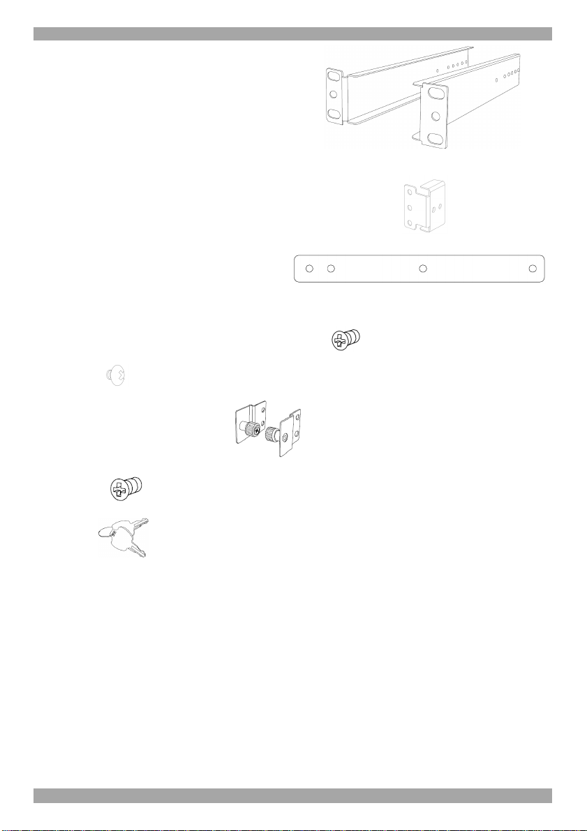
4. Hardware kit contents
Rail with front and rear bracket x 2,
for rack depth of 614 ~ 800 mm.
Right and left sides are different.
6
Page 8
SMARTRACK 116 IP
Long bracket x 2. (For increased rack
depth of 905 ~ 990mm)
Short bracket x 2
Bracket attachment x 2
Note! The short bracket and bracket attachment for a rack depth of 504~ 614 mm
and without a KVM switch connected to the drawer.
Flat screws x 6 (for rail mount to console body)
Screws x 6
Bracket A with thumbscrew x 2
Screws x4
Keys x 2.
5. Pre-installation guidelines
• Switch off all computers
• Place cables away from fluorescent lights, air conditioners, and machines that
are likely to generate electrical noise
• Ensure that the maximum distance between each computer and the SmartRack
116 IP does not exceed 30m/100ft
7
Page 9

USER GUIDE
5.1 Avoiding general rack mounting problems
Elevated operating ambient temperature
The operating ambient temperature of the rack environment may be greater than
the room ambient when installing into a closed or multi-unit rack assembly. So
install the equipment in an environment compatible with the maximum rated
ambient temperature.
Reduced airflow
Install the equipment in a rack in such a way that the amount of airflow required
for safe operation is not compromised.
Mechanical loading
Mount the equipment in the rack in such a way that a hazardous condition is not
achieved due to uneven mechanical loading.
Circuit overloading
When connecting the equipment to the supply circuit, consider the effect that
overloading of circuits might have on over-current protection and supply wiring.
Reliable earthing of rack-mounted equipment should be maintained. Give attention
to supply connections other than direct connections to the branch circuit (e.g. use of
power strips).
6. Connecting to a rack
Note! For increased rack depth of 905 ~ 990mm, first change the bracket, see
section 6.1 on page 11.
Note! The illustrations below show the connections to one side of the SmartRack
116 IP. The connections are the same for the other side.
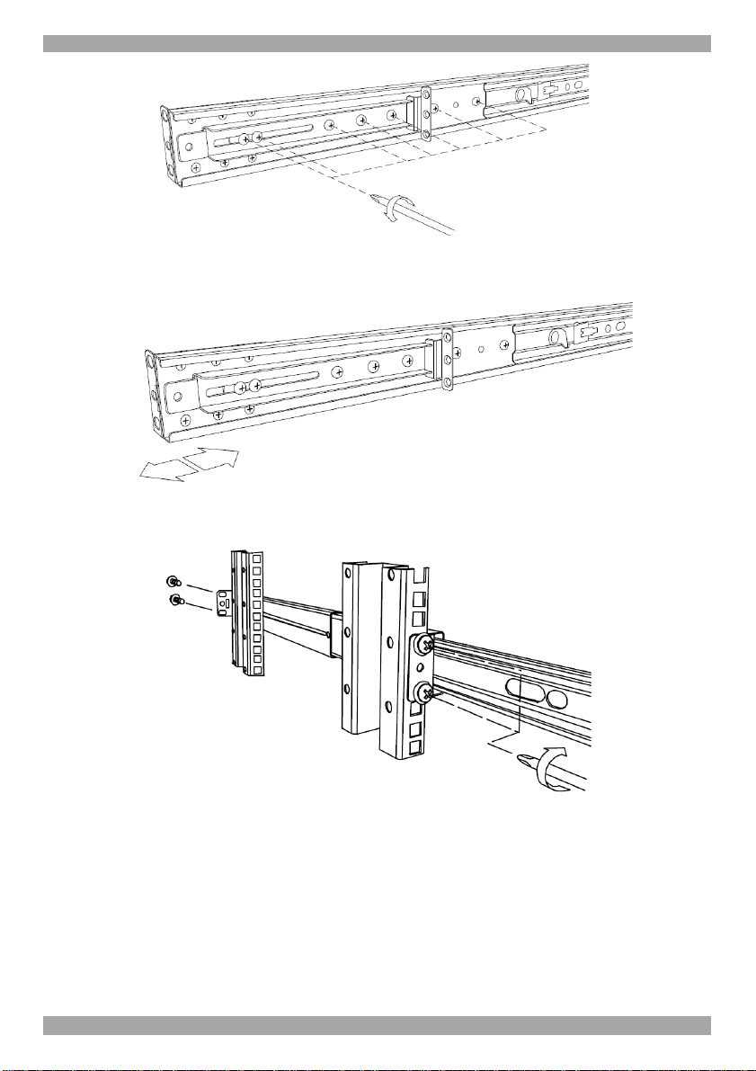
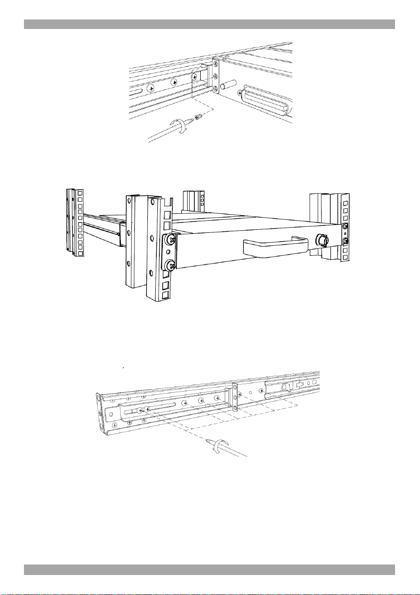
1. Move the rail until two screws appear, see Figure 1.
Figure 1 Exposing the 2 screws
2. Loosen slightly the 7 screws as shown below.
8
Page 10
SMARTRACK 116 IP
Figure 2 Loosen 7 screws
3. Adjust the rear bracket to fit your cabinet, see below.
Figure 3 Adjusting the bracket
4. Install the front and rear bracket onto the cabinet, see figure below.
Figure 4 Installing front and rear bracket on cabinet
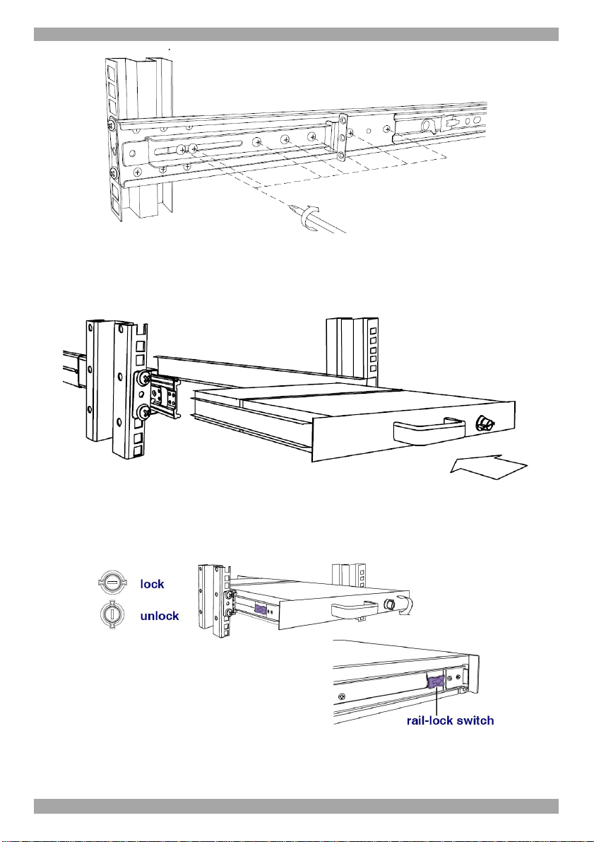
5. Tighten the 7 screws as shown below.
9
Page 11
USER GUIDE
Figure 5 Tightening the 7 screws
6. Repeat the steps above to connect the other rail to the other side of the rack.
7. Slide the SmartRack console between the rails as shown below.
Figure 6 Sliding the SmartRack between the rails
8. Unlock and pull both left and right rail–lock switches together – see below –
and push the console all the way into the rack.
Figure 7 Rail–lock switch
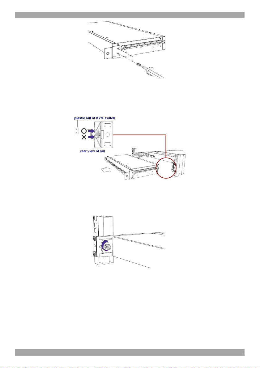
9. Connect three flat screws to the rear of the console on both sides. See figure
below.
10
Page 12
SMARTRACK 116 IP
Figure 8 Connecting three flat screws to the rear of the console
The console now sits snugly in the rack, see Figure 9.
Figure 9 Console in the rack
6.1 Using the longer bracket for rack depth of 905 ~ 990mm
To replace the bracket with the longer bracket:
1. Loosen the 7 screws as shown below.
Figure 10 Loosening the 7 screws
Remove the six (different) screws as shown below.
11
Page 13

USER GUIDE
Figure 11 Removing the six screws
2. Take the rear bracket out, see below.
Figure 12 Taking the rear bracket out
3. Insert the long bracket into the rail then adjust the bracket to fit your cabinet.
Tighten at least 2~3 screws along the length you need. See Figure 13.
Figure 13 Inserting and tightening the long bracket
4. Repeat the above steps for the other side.
5. Go to section 6 Connecting to a rack.
6.2 Connecting the KVM Switch 116 IP
1. Connect the bracket A to the sides of the Switch using the two 6mm screws
provided see figure below.
12
Page 14
SMARTRACK 116 IP
Figure 14 Connecting the bracket A to the sides of the Switch
2. Slide the Switch 116 IP into the rail and into the back of the SmartRack console
until you hear a click. See the figure below.
Figure 15 Slide switch into back of SmartRack
3. Secure the Switch 116 IP to the rail by inserting the thumbscrews through the
bracket and into the rail and tightening them, see Figure 16.
Figure 16 Tightening the thumbscrews
13
Page 15
USER GUIDE
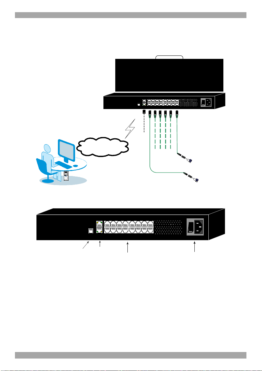
7. The SmartRack Switch system configuration
You connect servers to the 116IP switch via ROCs. Figure 17 illustrate the basic
configuration of the 116IP system.
10 11 12 13 14 15 169
MINICOM
SMARTRACK 116IP SWITCH
SMARTRACK 116IP SWITCH
User over IP
Internet / VPN / LAN
SERIAL
FLASH LAN
1 2 3 4 5 6 7 8
To servers
CAT5 cables
Up to 30M / 100ft
ROCs
to servers
0
I
Figure 17 SmartRack 116IP Switch system configuration
7.1 The 116 switch
MINICOM
SMARTRACK 116IP SWITCH
Flash
(download)
connector
10 11 12 13 14 15 169
SERIAL
FLASH LAN
1 2 3 4 5 6 7 8
LAN (Ethernet)
connector
Server ports
Figure 18 116IP Switch ports
14
0
I
Power
connector
Page 16
SMARTRACK 116 IP
7.1.1 Connector table
Connector Function
Serial This port is for future Serial functionality
Flash To update firmware of the analogue part of the 116 IP Switch
system - OSD, Switch, ROCs.
LAN Connect to 10/100 Mbit Ethernet. Yellow Led illuminates when
connected to LAN. Green LED illuminates when a remote session
is in progress
Server ports Connect to servers via ROCs
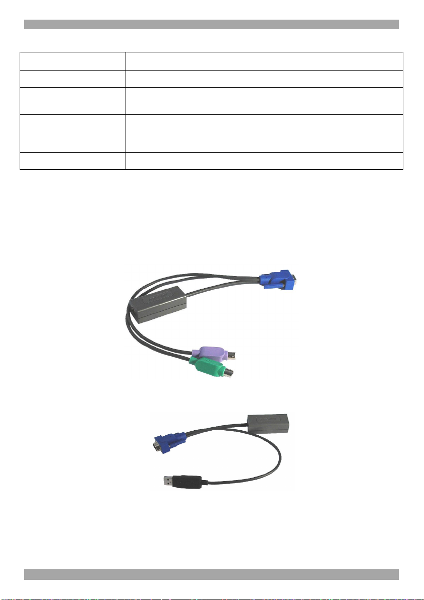
7.2 Connecting ROCs to servers
Each computer/server is directly connected to the SmartRack switch via the
appropriate ROC using CAT5 cable in a star configuration. No external power is
needed at the remote ROCs. The ROCs draw their power from the computer’s
keyboard port (ROC PS/2) or from the USB port (ROC USB). The figures below
illustrate the ROC PS/2 and ROC USB.
To computer’s
Video card
To computer’s
keyboard port
To computer’s
Figure 19 ROC PS/2
mouse port
To computer’s
Video Card
To computer’s
USB Port
Figure 20 ROC USB
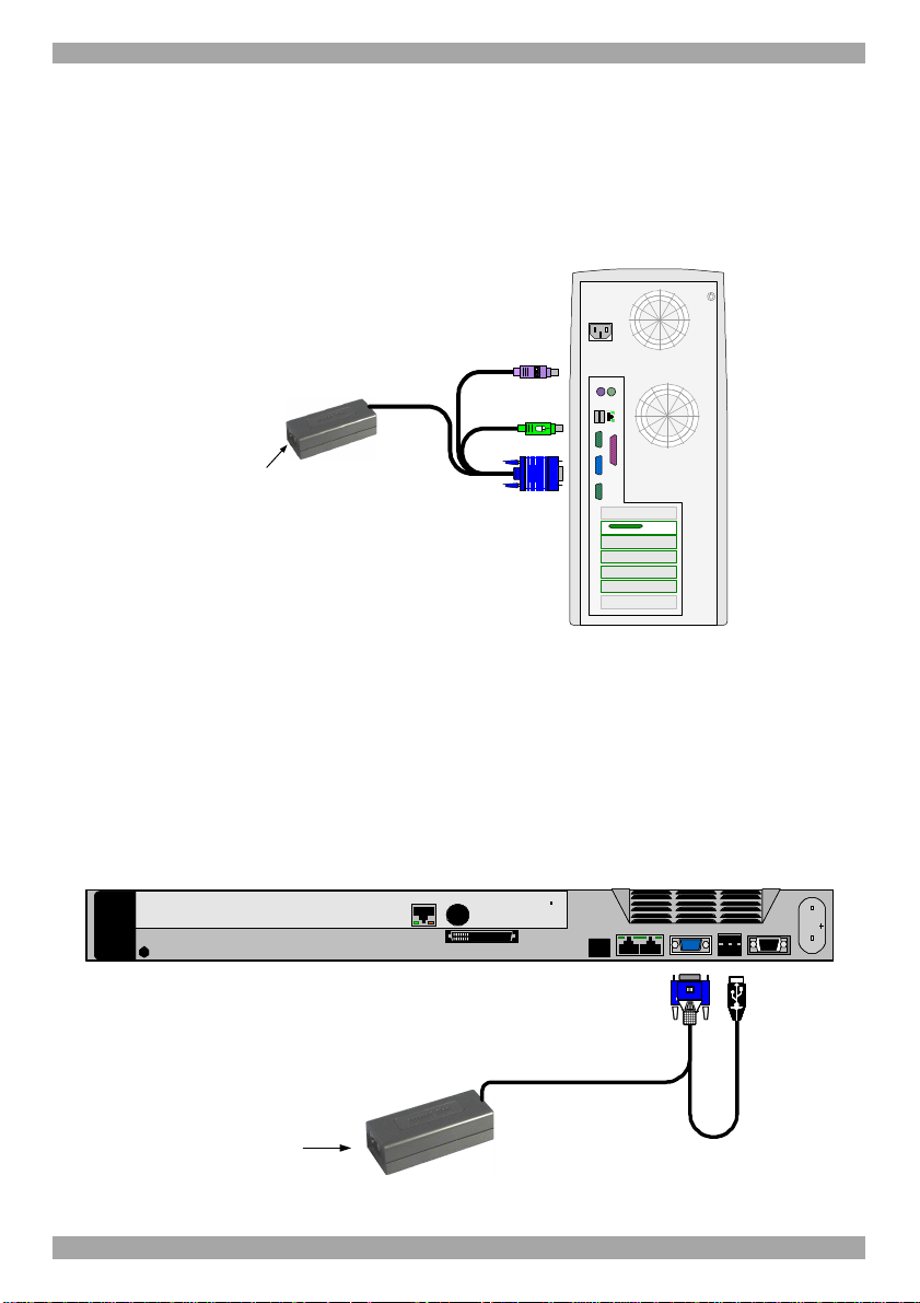
7.2.1 Connecting a ROC PS/2
Figure 21 illustrates the ROC PS/2 connections.
You can connect the ROC PS/2 to a powered on computer, but it must be in the
following order:
15
Page 17
USER GUIDE
1. Connect the Mouse connector to the computer’s Mouse port.
2. Connect the Keyboard connector to the computer’s Keyboard port.
3. Connect the Screen connector to the computer’s Video port.
Failure to connect in the above order while the server is running, may lead to the
mouse malfunctioning until the server is rebooted.
To Keyboard port
Keybd
Mouse
100T
Parallel
VideoSerial A
Serial B
PCI 33Mx32b
PCI 33Mx32b
PCI 33Mx32b
PCI 33Mx32b
SCSI
CAT5 cable to switch
Server port
To Mouse port
ROC PS/2
To Video port
Figure 21 ROC PS/2 connections
7.2.2 Connecting a ROC USB
The ROC USB supports Windows 98 SE and later, MAC, SUN, SGI and all
modern Linux distributions. Figure 22 illustrates the ROC USB and its connections.
To connect the ROC USB:
1. Connect the Screen connector to the computer’s Video port.
2. Connect the USB connector to the computer’s USB port.
ROC USB
CAT5 cable to switch
Server port
To Video port
To USB port
Figure 22 ROC USB
16
Page 18

SMARTRACK 116 IP
7.3 Connecting the CAT5 cables
1. Connect one connector to the ROC’s RJ45 port.
2. Connect the other connector to one of the SmartRack Switch Server ports.
3. Follow the above 2 steps for each computer.
7.4 Connecting to the network
Connect the network cable to the LAN port. This must be done before powering on
the SmartRack 116IP Switch.
7.5 Connecting the power supply
1. Connect the switch to the power supply using the Power cord provided. Only
use the Power cord supplied with the unit.
2. Power on the switch.
8. Terminology
Below are some terms and their meanings used in this guide.
Term Meaning
Target server The computers/servers that are accessed remotely via the
SmartRack 116 IP.
Client computer The PC running a remote SmartRack 116 IP session
Remote session The process of remotely accessing and controlling Target
Servers connected to SmartRack 116 IP from a user
workstation
9. Initial settings - Default IP address
The following sections provide instructions for setting the IP address for the
SmartRack 116 IP unit. See Figure 23 for an overview of the boot-up process.
By default, SmartRack 116 IP boots with an automatically assigned IP address
from a DHCP (Dynamic Host Configuration Protocol) server on the network. The
DHCP server provides a valid IP address, gateway address and subnet mask.
To identify the IP address, the SmartRack 116 IP MAC address appears on the
underside of the SmartRack 116 IP box. The device number (D.N.) can also be
found there.
If no DHCP server is found on the network, SmartRack 116 IP boots with the static
IP address:192.168.0.155.
17
Page 19

USER GUIDE
Note! If a DHCP server later becomes available, the unit picks up the IP settings
from DHCP server. To keep the static IP address, disable DHCP – explained in
section 11.1 on page 21.
9.1 Static IP addresses for a number of units
Where you want to connect more than 1 SmartRack 116 IP to the same network
and there is no DHCP server, or you want to use static IP addresses, do the
following:
Connect the SmartRack 116 IP units one at a time and change the static IP address
of each unit before connecting the next unit.
18
Page 20

SMARTRACK 116 IP
Unit boots up
Device network setting
is set to obtain IP address from
DHCP Server
Yes
Is DHCP Server
present in the
connected LAN?
Yes
IP address is assigned by the DHCP server
To access the configuration page of the unit, open IE 6.0 or higher and type:
No
https://IPaddress/config
Default password: access
Every 5 minutes
No
Default user: admin
Set static IP
(deselect the DHCP
and set the IP)
Yes
Device IP is:
192.168.0.155
No
The unit operates with the static IP address
Figure 23 boot-up process
19
Page 21
USER GUIDE
10. Logging into the Web interface
Client computer operating system. Windows 2000 or higher, with Internet
Explorer 6.0 or later version. 128 bit encryption support is required.
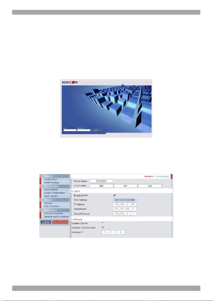
Complete the initial setup via the Web configuration interface:
1. Open your Web browser (Internet Explorer version 6.0 or higher).
2. Type the SmartRack 116 IP system IP address - https://IP address/config - and
press Enter. The login page appears, see Figure 24.
Figure 24 Login page
3. Type the default Administrator user name - admin - and password - access (both lower case).
4. Press Enter. The Web interface opens at the Network Configuration page. See
Figure 25.
Figure 25 SmartRack 116 IP Web interface
5. Bookmark the page for easy reference.
10.1 SSL Certificate notes
When first connecting to SmartRack 116 IP’s https configuration page, 2 browser
security warnings appear. Click Yes to proceed.
20
Page 22

SMARTRACK 116 IP
The first warning disappears upon first SmartRack 116 IP client installation, when
Minicom’s root certificate is installed.
11. Network > Configuration
Consult your Network Administrator for the network settings.
Device name - Type a name for the SmartRack 116 IP. Default device name
consists of the letter ‘D’ followed by the 6-digit device number (D.N.) found on the
silver label on the underside of the SmartRack 116 IP box.
3 TCP Ports - Choose any 3 TCP ports from port #800 to 65535. When the
SmartRack 116 IP is a standalone system the ports do not have to be consecutive.
When part of the KVM.net system, the ports must be the consecutive default ports
of 900, 901 and 902. These default ports are suitable for the majority of
installations. (The port numbers can be changed from KVM.net if needed).
Note
Firewall or router security access list must enable inbound communication through
the selected TCP ports for the SmartRack 116 IP’s IP address.
For Client computer access from a secured LAN, the selected ports should be open
for outbound communication.
11.1 LAN 1
Under LAN 1 in Figure 25, is the following:
Enable DHCP – When a DHCP server is active on the same network to which
SmartRack 116 IP is connected, DHCP provides automatic IP assignment.
When DHCP is disabled – (Recommended) – You can assign a fixed IP address to
the SmartRack 116 IP.
Consult your Network Administrator regarding the use of the DHCP. Note! Where
you have access to the server – your configured (or default) SmartRack 116 IP
device name will appear on the DHCP server’s interface, making it easy to locate.
When DHCP is disabled, enter the IP Address, Subnet Mask, and Default
Gateway for LAN 1, as given by your Network Administrator.
21
Page 23
USER GUIDE
11.2 KVM.net
KVM.net is a centralized IP based system for secure control of servers and network
devices, power and user administration in the data center environment. KVM.net
combines Out-Of-Band, KVM via IP access with modern IT standards and
requirements. It is the most comprehensive remote server maintenance solution
available in the market today.
Enable KVM.net - Check this option to allow SmartRack 116 IP unit to be
remotely managed by Minicom’s KVM.net system.
Manager Auto Discovery – when checked, KVM.net automatically detects the
SmartRack 116 IP, if it resides on the same network segment.
Manager IP – If SmartRack 116 IP resides on a different segment, type the static
IP address of the KVM.net Manager. (We advise typing the static IP address of the
KVM.net Manager even if the SmartRack 116 IP resides on the same network
segment as the KVM.net Manager).
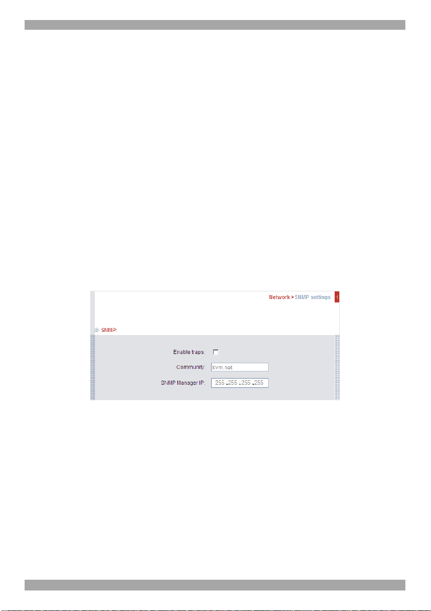
12. Network > SNMP Settings
From the menu click SNMP settings. The following appears.
Figure 26 SNMP
From this page you can activate or deactivate SNMP logging.
Enable traps - Check to enable sending SNMP traps of SmartRack 116 IP events
and operation.
Community – type the SNMP community.
SNMP Manager IP - Enter the SNMP Server IP address.
22
Page 24

SMARTRACK 116 IP
"Server Busy ask
12.1 SNMP Events table
The table below list all events recorded.
Event Text Code Comment
"System Boot" 1010 Reported upon device boot up.
for disconnect..."
"User login
succeeded"
"Login failed
wrong user
name or
password"
"Login not
succeeded
server busy"
"Logout" 1070 User Logout (end of remote access session).
"Disconnected
by another user"
"Hardware
Failure"
"Hard reset
power cycle
command"
"Viewer login" 1230 User connected in view-only mode (while another user is connected in a
1030 Attempt to connect when another user is already connected. The 2nd user has
permission for takeover, sent before the 2nd user actually takes over the
session.
1040 On every successful user login to the device.
1050 Login failed due to wrong user name or password.
1060 Login denied since a user with higher permission is connected (takeover not
allowed).
1110 Takeover has been successfully performed; the previous user has been
disconnected.
1200 Device internal hardware failure. Try disconnecting any other attached device
and re-boot. If problem persists contact technical support.
1220 Power cycle command issued, only relevant when a special power-cycle
product is attached to the device (e.g., KBPower).
regular session).
"Viewer logout" 1240 User connected in view-only mode has disconnected.
"Global access
disabled "
“Block User
Account”
Successful User
Login
Login is not
successful –
wrong user
access level.
Wrong user
name or
password
1250 Device has been blocked for access by an administrator; remote access is
disabled until the device is unblocked.
1260 User blocked due to too many login attempts failure per policy in
configuration.
2010 Successful User Login CONF_USER_EVENT_LOGIN_SUCCEEDED
2020 Login is not successful – wrong user access level.
CONF_USER_EVENT_LOGIN_NOT_SUCCEEDED_WRONG_LEVEL
2030 Wrong user name or password. Login is not successful.
CONF_USER_EVENT_LOGIN_NOT_SUCCEEDED_WRONG_USER_NAME_OR_PASSWOR
D
23
Page 25

Event Text Code Comment
Login is not
successful
because server
is busy.
DHCP server
setting has been
changed
Network IP
address changed
Network Subnet
Mask changed
Network Default
Gateway
changed
User Logged out
from Config
TCP Port was
changed
Remote Access
type was
changed
Security settings
changed
Restore default
factory settings
successful
Restore default
factory settings
failed
Firmware
Upgrade
successful
Firmware
Upgrade failed
2040 Login is not successful because server is busy.
CONF_USER_EVENT_LOGIN_NOT_SUCCEEDED_SERVER_BUSY
2060 DHCP server setting has been changed
CONF_DHCP_CHANGED
2070 Network IP address has been changed CONF_IP_CHANGED
2080 Network Subnet Mask has been changed CONF_SNMASK_CHANGED
2090 Network Default Gateway has been changed CONF_DG_CHANGED
2100 User Logged out from Config CONF_LOG_OUT
2110 TCP Port was changed CONF_TCP_PORT_CHANGED
2120 Remote Access type was changed CONF_REMOTE_ACCESS_CHANGED
2140 CONF_SECURITY_CHANGED
2150 CONF_RESTORE_FACTORY_OK
2160 CONF_RESTORE_FACTORY_FAILED
2170 CONF_UPGRADE_OK
2180 CONF_UPGRADE_FAILED
USER GUIDE
24
Page 26

SMARTRACK 116 IP
13. Administration > User Settings
From the menu click User Settings, Figure 27 appears.
Figure 27 User Settings
On this page an Administrator creates and edits users.
There are 3 levels of user access:
• Administrator
• User
• View only
Administrator
An Administrator has unrestricted access to all windows and settings and can “take
over” any active session (explained in section 21.1 on page 33). An Administrator
can change the name and password and Target server permissions of all users.
User
A User can access/control Target Servers, but cannot use the advanced mouse
settings.
A User has no access to the Web configuration interface.
View only
View only can view the screen of the currently accessed Target Server without
keyboard and mouse control. A “view only” indicator appears on the viewer’s local
mouse pointer.
25
Page 27

USER GUIDE
13.1 Adding a user
To add a user:
1. Click and type a name and a password. The password must be at
least 6 characters – letters or numbers, and must not include the user name, even
if other characters are added.
Note! The following “special” characters: &, <, >, ”, {, } cannot be used for
either the user name or password.
Depending on the security level chosen the user name and password parameters
are different. See section 16 on page 28.
2. Select the permission type from the Permission box.
3. Click , the user appears in the list of users.
13.2 Editing a user
To edit a user:
1. Select the user from the list.
2. Click . You can now change all the parameters – user name,
permission and password.
3. Click , the changes are saved.
13.3 Deleting a user
To delete a user:
1. Select the user from the list.
2. Click .
3. Click , the changes are saved.
13.4 Blocking a user
An alternative to deleting a user is blocking a user. This means that the user’s name
and password is stored, but the user is unable to access the system. Check Block to
block a user. Uncheck Block to allow the user access.
26
Page 28

SMARTRACK 116 IP
14. Administration > Switch Configuration
Give the servers connected to the SmartRack 116 IP unique names, so that users
accessing the system can identify the servers easily.
To do so:
1. From the menu click Switch Configuration. The Switch Configuration window
appears, see Figure 28.
Figure 28 Switch Configuration
2. In the Server Name section change the name of the connected servers by
selecting the server name and typing a new name. Click to save
changes.
Install switch definition file
In the event that Minicom’s Technical Support updates the Switch Definition file,
the file will be available in the Support section of our website www.minicom.com.
1. Load the file onto the Client computer.
2. Locate and install the Switch Definition file. The switch definition file is
replaced.
15. Administration > User Targets
By default access is allowed to all servers for all user types. You may define the
access rights of each user separately.
To do so:
1. From the menu click User Targets. The User Targets Configuration window
appears, see Figure 29.
27
Page 29

USER GUIDE
Figure 29 User Targets Configuration
2. Select a user from the User drop-down menu.
3. Check the Target servers the user can access (according to his access
permissions). To select all Target servers, press Select All.
4. Click Apply, the selection is saved.
5. Repeat the above steps for other users.
16. Security > Settings
Configure the security features, such as Account Blocking, Password Policy and
Idle Timeout, as explained below.
From the Security section click Settings, the Security Settings appear, see Figure
30.
Figure 30 Security Settings
The Security Settings fields:
Account Blocking – decide on the number of attempts to login with a wrong
username or password after which there is a time lock or a total block.
28
Page 30

SMARTRACK 116 IP
Password Policy – You have the option of a standard or high security level of
password. The table below shows the parameters of the 2 options.
Standard security policy High security policy
6 characters or more 8 characters or more must include at least 1 digit
Must not include the user name Must not include the user name
and 1 upper case letter and 1 “special” character
as follows !@#$%^*()_-+=[]’:;?/
Check the box to enable the high security password policy. Unchecked, the
standard security policy applies.
Idle Timeout – Select the Timeout inactivity period after which the user is
disconnected from the system. Choose No Timeout to disable Timeout.
Click to save any configuration changes done to the Security
Settings page. The SmartRack 116 IP system restarts with the new changes.
17. Security > SSL Certificate
You can install an SSL certificate.
To do so:
From the menu, select SSL Certificate, the install SSL Certificate page appears,
see Figure 31.
Figure 31 Install SSL Certificate page
Certificate File - Browse to locate the cer file.
Private File - Browse to locate the private key file.
Key Password - Type the “private key” password.
Click .
29
Page 31

USER GUIDE
18. Maintenance > Firmware Upgrade
Upgrade the SmartRack 116 IP firmware to take advantage of new features.
Download the firmware from the Support section of Minicom’s website –
www.minicom.com. Save the firmware file on the Client computer.
From the menu select Firmware Upgrade. The Firmware Upgrade window
appears showing the current firmware version see Figure 32.
Figure 32 Firmware Upgrade
1. Locate and upload the firmware file.
2. Verify the current and uploaded version of the firmware.
3. Click . The upgrade starts. On completion, click .
The unit reboots. After about 30 seconds the Login page appears.
Note!
Depending on the type of firmware upgrade, the following settings may be erased:
User settings, server names, mouse and video adjustments. For more information
refer to the firmware release notes.
The network settings remain intact.
19. Restore Factory Settings
You can restore the SmartRack 116 IP unit to the factory settings. This restores the
original SmartRack 116 IP parameters, resetting all the information added by the
administrators, including: Network settings*, Servers, Switches, Users, Passwords
etc.
* You have the option to preserve Network settings – explained below.
Warning! Once reset the data cannot be retrieved.
To restore factory settings:
1. From the menu select Restore Factory Settings. Restore Factory Settings
appears see Figure 33.
30
Page 32

SMARTRACK 116 IP
Figure 33 Restore factory settings
2. Check the box if you want to preserve Network settings.
3. Click .
20. Saving changes and logging out
To save any configuration changes and restart the SmartRack 116 IP click
. You must press after making changes to the following
pages:
• Network>Configuration
• Network>SNMP Settings
• Security>Settings
• Security>SSL Certificate
To exit the Configuration menu and close the session, click .
Only one Administrator can log into the Configuration area at a time. An idle
timeout of 30 minutes terminates the session.
21. Starting a remote session
At a Client computer open Internet Explorer (6.0 and above) and type the
SmartRack 116 IP’s IP address. https://IP address. (Note! Only SSL connections
are allowed, therefore type HTTPS before the IP address or the name of the
SmartRack 116 IP). The Login page appears. Type your username and password
and press Enter. By default, the user name is: admin and the password is access,
(both lower case).
Windows Vista Note! To login to the Web configuration interface with Windows
Vista, run Internet Explorer as Administrator. To do this, right-click the Internet
Explorer icon on the Taskbar and select Run as administrator. See figure below.
31
Page 33
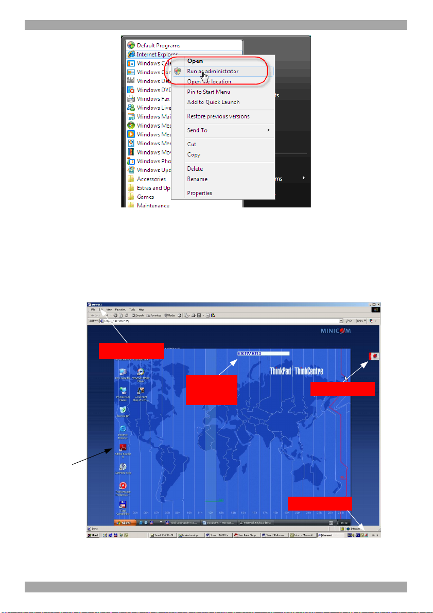
USER GUIDE
Figure 34 Select Run as administrator
On first connection install the Minicom certificate and ActiveX control. You must
login as an Administrator to your computer to install the ActiveX control. Once the
ActiveX control is installed, all types of users can login.
On connecting, the screen of the lowest numbered Target Server that the user has
permission to access appears. Figure 35 illustrates the remote session window.
Server name
Server
confirmation
label
Remote
screen
border
Toolbar icon
Minicom icon
Figure 35 Remote console window
32
Page 34
SMARTRACK 116 IP
On the remote console you have the following:
Server Confirmation label – This confirms the identity of the current server
accessed and disappears by default after 30 seconds, (this period can be adjusted in
the OSD – explained in Section II of the guide). It appears again when switching to
a different server. The currently accessed server identity can be checked any time
by looking at the Server name on the Internet Explorer title bar.
Toolbar icon – This is the minimized toolbar from which you switch and configure
the system.
Minicom icon – Hold the mouse over the icon to view information about current
server, connection time and video mode.
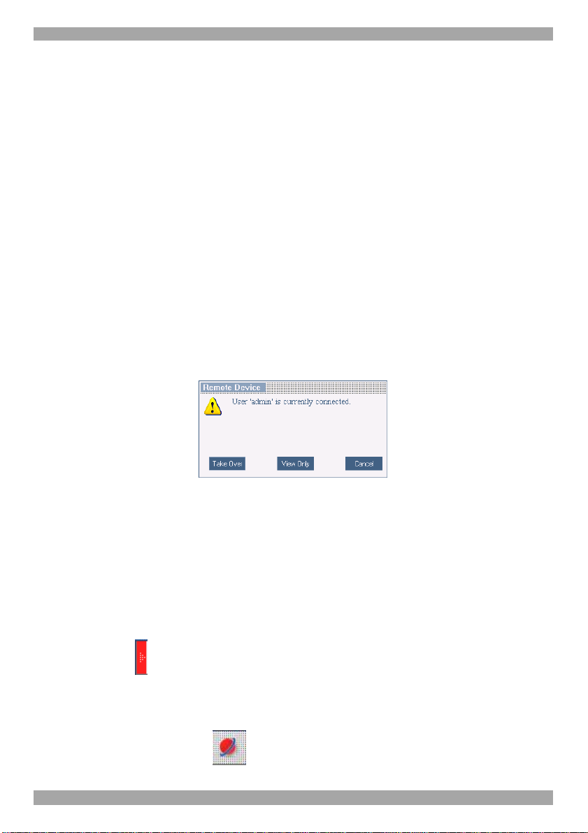
21.1 Taking over a busy remote session
While only one user can have control, many users can be connected
simultaneously. When connecting to a busy Target Server an Administrator has the
option to take over the Target Server. A User only has this option when the current
session is run by another User, but not by an Administrator. The following message
appears
Figure 36 Busy remote session options
Choose to Take Over or View Only or Cancel.
When watching a screen in View Only mode you can Double click inside the
Remote screen border – see Figure 35 – to take over the remote control. The
current user sees a message stating that control has been taken over.
21.2 The Toolbar
To maximize the Toolbar:
Click the arrow . Click again to minimize the Toolbar.
When maximized, the Toolbar can be dragged and dropped to anywhere on the
screen, by dragging the icon . When minimized the icon glides to a side of the
screen.
33
Page 35
USER GUIDE
To hide the Toolbar, either:
Double-click the SmartRack 116 IP System tray icon .
Or
Press F9.
To display the Toolbar repeat the above action. See also page 42.
21.3 Switching to a different server
To connect to a different server:
1. From the Toolbar, click , or right-click . A list of available servers
appears. The currently connected server is highlighted in bold.
2. Click the desired server name. The screen of the selected server appears.
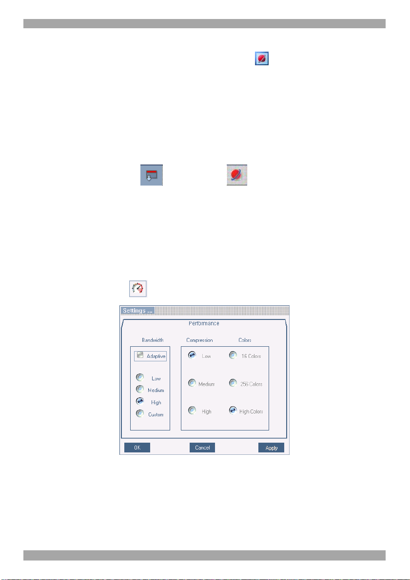
21.4 Changing the performance settings
You can alter the bandwidth settings from the Toolbar.
To alter the settings:
From the Toolbar, click . The Settings.. Dialog box appears, see Figure 37.
Figure 37 Settings.. Dialog box
Bandwidth
Choose from the following options
Adaptive – automatically adapts to the best compression and colors according to
the network conditions. (Not recommended because network parameters may
change frequently impacting on user experience).
34
Page 36

SMARTRACK 116 IP
Low - Select Low for high compression and 16 colors.
Medium - Select medium for medium compression and 256 colors. Medium is
recommended when using a standard internet connection.
High - For optimal performance when working on a LAN, select High. This gives
a low compression and high colors (16bit).
Custom – You cam choose your own compression and color levels.
Click OK. The screen of the last accessed Target Server appears.
21.5 Adjusting the Video settings
To change the video settings:
From the Toolbar, click . You have the following options:
• Refresh
• Manual Video Adjust
• Auto Video Adjust
Each option is explained below.
21.5.1 Refresh
Select Refresh to refresh the Video image. Refresh may be needed when changing
the display attributes of a Target Server.
21.5.2 Manual Video Adjust
Use the manual video adjustment for fine-tuning the Target Server video settings
after auto adjustment or for adapting to a noisy environment or a non-standard
VGA signal or when in full-screen DOS/CLI mode.
To adjust the video manually:
Click Manual Video Adjust. The manual controls appear, see Figure 38. Also a red
frame appears around the screen. This represents the screen area according to the
Server's screen resolution. Perform the adjustments inside and relative to this
frame.
35
Page 37

USER GUIDE
Figure 38 Manual Video Adjustments controls
Brightness / Contrast - use the scales to adjust the brightness and contrast of the
displayed image. Move the sliders to change the displayed image. Click in the area
of the sliders for fine-tuning.
For the following controls choose the appropriate measurement.
Horizontal Offset - defines the starting position of each line on the displayed
image.
Vertical Offset - defines the vertical starting position of the displayed image.
Phase - defines the point at which each pixel is sampled.
Scale – defines the scale resolution of the session image.
Select Filter - defines the filter of the input video from the server. A higher filter
reduces the noise level but makes the image heavier.
Noise Level - represents the Video "noise" when a static screen is displayed.
21.5.3 Auto Video Adjust
To adjust the video automatically:
Click Auto Video Adjust. The process takes a few seconds. If the process runs for
more than 3 times, there is an abnormal noise level. Check the video cable and
verify that no dynamic video application is running on the Target Server’s desktop.
Perform the procedure where necessary for each Target Server or new screen
resolution.
36
Page 38
SMARTRACK 116 IP
21.6 Power cycle
This button . is for future Serial power management options.
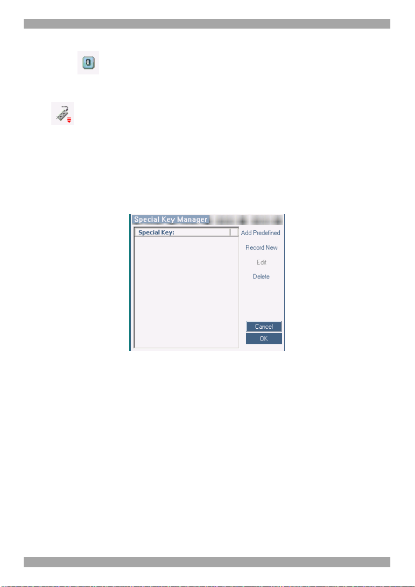
21.7 Keyboard key sequences
Click . A list of defined keyboard sequences appears. When clicked, these
transmit directly to the Target Server, and will not affect the Client computer.
For example, select Ctrl-Alt-Del to send this three key sequence to the Target
Server to initiate its Shutdown/Login process.
To add a keyboard sequence:
Click Add/Remove. The Special Key Manager box appears see Figure 39.
Figure 39 Special Key Manager box
To add a predefined sequence:
1. Click Add Predefined. A list of sequences appears.
2. Select the desired sequence and click OK. The sequence appears in the Special
Key Manager box.
3. Click OK. The sequence appears in the Keyboard Key sequence list.
To record a key sequence:
1. From the Special Key Manager box press Record New. The Add Special Key
Dialog box appears, see Figure 40.
37
Page 39

USER GUIDE
Figure 40 Add Special Key Dialog box
2. Give the key sequence a name in the Label field.
3. Click Start Recording.
4. Press the desired keys. The key sequence appears in the area provided.
5. Click Stop Recording.
6. Click OK.
To edit a key sequence:
1. From the Special Key Manager Dialog box select the desired key.
2. Click Edit.
3. Click Start Recording
4. Press the desired keys. The keys appear in the area provided.
5. Click Stop Recording.
6. Click OK.
21.8 Synchronizing mouse pointers
When working at the Client computer, two mouse pointers appear: The Client
computer’s is on top of the Target Server’s. The mouse pointers should be
synchronized. The following explains what to do if they are not synchronized.
Warning
Before synchronizing mouse pointers adjust the video of the Target Server,
(explained above) otherwise mouse synchronization may not work.
38
Page 40

SMARTRACK 116 IP
21.8.1 Aligning the mice pointers
When accessing the Target Server, the mice may appear at a distance to each other.
To align the mouse pointers:
From the Toolbar click / Align or press Ctrl+M simultaneously. The mice
align.
21.8.2 Calibrating mice pointers
A Target Server may have a different mouse pointer speed to the Client computer.
Calibrating automatically discovers the mouse speed of the Target Server and
aligns the two pointers.
To perform the calibration when the Target Server Operating system is, Windows
NT4, 2000 or 98:
From the Toolbar click / Calibrate. SmartRack 116 IP saves this alignment
so calibration is only needed once per Target Server.
If the Video Noise Level is above zero, calibration may not work. Go to Video
Adjustment and try to eliminate the noise by pressing Auto video adjust and/or
adjusting the bars in Manual video adjust, then perform the mouse calibration.
Note! If the mouse settings on the Target Server were ever changed, you must
synchronize mouse pointers manually, as explained below.
21.8.3 Manual mice synchronization
If the mouse settings on the Target Server were ever changed, or when the
Operating system on the Target Server is, Windows XP / 2003 Server / Vista/ 2008
Server, Linux, Novell, SCO UNIX or SUN Solaris you must synchronize the
mouse pointers manually.
To manually synchronize mouse pointers:
1. From the Toolbar click / Manual Settings. The Mouse Settings Dialog
box appears see Figure 41.
39
Page 41

USER GUIDE
Figure 41 Mouse Settings Dialog box
2. Select the Target Server’s Operating System and click OK. Instructions and
sliders appear.
3. Follow the instructions and set any relevant sliders to the same values as set in
the Target Server’s Mouse Properties window.
2 examples!
For Windows XP, 2003 Server, Vista and 2008 Server. Go to the Mouse settings
on the Target Server and uncheck Enhance pointer precision.
For Windows NT4, 98, ME, 2000. If Mouse Properties were ever changed for the
Target Server – even if they have been returned to their original state - uncheck
default - .
Click OK. The mouse pointers should be synchronized.
21.8.3.1 USB
The USB option in Mouse Settings box is available for ROC USB, for unsupported
operating systems and SUN Solaris. Use this option if you are sure of the custom
acceleration algorithm you are using, or have been informed so by customer
support.
21.8.3.2 Advanced – Mouse Emulation
In the Advanced Mouse settings, you can set the type of mouse connected to
SmartRack 116 IP’s local console.
Click the Mouse Emulation Dialog box appears, see Figure 42.
40
Page 42

SMARTRACK 116 IP
Figure 42 Mouse Emulation Dialog box
Select the mouse connected to the Local Console port on the SmartRack 116 IP,
e.g. if the local mouse is a 2 button mouse, select Standard Mouse.
Max Rate - this defines the maximum mouse report rate. For Sun Solaris the
default value is 20 in order to support older Sun versions.
21.9 Minicom icon menu features
Right-click the Minicom icon , a menu appears. From this menu you can
access the connected devices. You also have the following features:
Disconnect – You can disconnect the session by clicking Disconnect.
About - Click About to verify the Client, Firmware, KME (Keyboard/Mouse
Emulation firmware) and Switch file versions installed on your SmartRack 116 IP.
Local Settings – Click Local settings, the Client Configuration Dialog box
appears, see Figure 43
Figure 43 Client Configuration Dialog box
Pointer type – From the Drop-down menu you can change the Client computer
mouse pointer to appear as a dot or to not appear at all.
Hide Toolbar – Check this option to hide the Toolbar from the next reconnection
onwards. To toggle the Toolbar on and off, press F9 or double-click the System
tray icon . See above page 33.
41
Page 43

USER GUIDE
Full Screen Mode - Check this option to make the remote session screen appear in
full screen mode from the next reconnection onwards. To toggle the full screen
mode on and off, press F11. (Also see section below).
Configuration – This only appears in the menu when an Administrator is logged
in. Click Configuration to access the Web configuration interface.
21.10 Full screen mode
Work on the Target Server as if you are working on a local computer, with full
screen mode.
To work in full screen mode:
1. Ensure that the Client computer has the same screen resolution as the Target
Server.
2. Press F11. The Internet Explorer window disappears, leaving the Internet
Explorer menu bar at the top.
3. Right click the Internet Explorer menu bar and check Auto-Hide. The Internet
Explorer menu bar disappears. You are in full screen mode.
To exit full screen mode:
Press F11. Or place the mouse at the top of the window to display the Internet
Explorer toolbar and click the Restore button.
Note! Full screen mode can also be activated from the Toolbar menu, see page 42.
21.11 Disconnecting the remote session
To disconnect the session, on the Toolbar, click . The Login page appears.
You can re-login, or close the browser window to disconnect the session.
22. Troubleshooting - Safe mode
From the Safe mode you can:
Restore factory defaults - When you cannot access the system e.g. you have
forgotten the Username or Password, restore factory defaults from the Safe mode.
(Section 19 on page 30 explained how to restore factory settings from the Web
interface).
Restore the device firmware – If during a firmware update there is a power
failure and you can no longer access the system you can restore the device
firmware from the Safe mode.
42
Page 44

SMARTRACK 116 IP
22.1 Entering Safe mode
To enter Safe mode:
1. Press and hold down the Local button for 3-4 seconds and at the same time
power up the SmartRack 116 IP. The device boots up in Safe mode.
2. Wait until the unit finishes booting (1-2 minutes).
3. You need to know the IP address of the SmartRack 116 IP. The IP address
depends on whether there is a DHCP server on the network. If there is, the
DHCP server assigns an IP address to the SmartRack 116 IP. If there is no
DHCP server, the unit boots with the static IP address 192.168.2.155. See
Figure 44 for an overview of this procedure.
Figure 44 Safe mode procedure
Open Internet Explorer and type the following into the Address box: http://IP
address/config. (Do not start the address with https). The Login page appears,
see Figure 45.
43
Page 45

USER GUIDE
Figure 45 Login page
4. Type username: admin , password: SAFEmode. (Case sensitive). (This
username and password works only in Safe mode). A menu appears, see Figure
46.
Figure 46 Safe mode menu
22.2 Restoring factory defaults
To restore factory defaults:
1. From the menu choose Restore Factory Settings. A warning appears see
Figure 47.
Figure 47 Warning
2. Click . A further warning appears, see below.
44
Page 46

SMARTRACK 116 IP
Figure 48 Warning
3. Click OK, the factory defaults are restored. When the process finishes Figure 49
appears.
Figure 49 Reboot
4. Click Reboot to restart the unit.
22.3 Restoring the device firmware
Contact Minicom Technical Support support@minicom.com, to receive the
Upgrade firmware required to restore the device firmware. Save the Upgrade
firmware on the hard disk of a computer connected to the network.
To restore the device firmware:
1. From the Safe mode menu choose Firmware Upgrade.
2. Locate the Upgrade firmware and click Install, then click Start Upgrade. The
firmware upgrades.When the process finishes Figure 50 appears.
3. Click Reboot to restart the unit.
Figure 50 Reboot
45
Page 47

USER GUIDE
Section II
Section II explains how to operate the SmartRack 116 IP Switching system locally
(sections 23 and 24) and how to upgrade the SmartRack 116 IP firmware (section
25). Section 25.5 deals with troubleshooting.
23. Switching between computers
Switch between the connected computers by either
• Keyboard hotkeys
• The OSD (On Screen Display)
The OSD is also the place to adjust various settings as explained below.
When switching computers the illuminated LED of the top bank indicates which
computer is currently selected.
23.1 The keyboard hotkeys
To switch to the next computer forwards press Shift then, +. Release Shift, before
pressing +.
To switch to the next computer backwards press Shift then, -. Release Shift, before
pressing -.
Note! With a US English keyboard you can use the + key of the alphanumeric
section or of the numeric keypad. With a Non-US English keyboard only use the +
key of the numeric keypad.
24. The OSD
To display the OSD:
Press Shift twice. The OSD Main window appears. See Figure 51. Lines with
yellow text show active computers. Lines with blue text show inactive computers.
The Type column indicates whether a computer “C” or another switch “S” is
connected to the port.
46
Page 48

SMARTRACK 116 IP
Port number
appears here
Instruction
keys
C=computer
Figure 51 OSD Main window
24.1.1 Navigating the OSD
To navigate up and down use the Up and Down arrow keys.
To jump from one column to the next (when relevant) use the Tab key.
To exit the OSD or return to a previous window within the OSD press Esc.
24.1.2 Selecting a computer
To select a computer:
1. Navigate to the desired computer line.
Or, type the port number of the desired computer.
2. Press Enter. The selected computer is accessed. A confirmation label appears
showing which computer is accessed.
Note! When the OSD is displayed you cannot select computers using the front
panel Select buttons or the keyboard hotkeys.
24.1.3 The OSD settings (F2)
Press F2. The OSD Settings window appears see Figure 52.
Figure 52 Settings window
47
Page 49
USER GUIDE
Note! When the OSD is password protected (explained below) only the
Administrator has access to the F2 settings window.
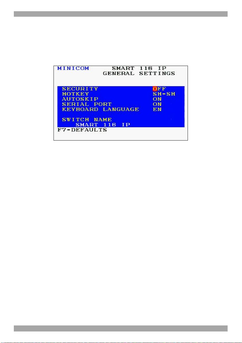
24.1.4 The General settings
With the GENERAL line highlighted, press Enter. The General settings window
appears see Figure 53.
Figure 53 General Settings window
From this window you can do the following:
24.1.4.1 Security
The OSD comes with an advanced password security system that contains 3
different security levels. Each security level has different access rights to the
system.
These levels are as follows:
24.1.4.2 Administrator (Status A)
The Administrator can:
• Set and modify all Passwords and security profiles
• Fully access any computer
• Use all OSD functions
24.1.4.3 Supervisor (Status S)
The Supervisor can:
• Fully access any computer
• Access the following OSD functions only –F4 Scan, F5 Tune and F6
Moving the Confirmation label.
48
Page 50

SMARTRACK 116 IP
24.1.4.4 User (Status U)
There are 6 different Users in the SmartRack 116 IP system. Each User has a
Profile set by the Administrator that defines the access level to different computers.
There are 3 different access levels; these are explained on page 52.
24.1.4.5 Activating password protection
By default OSD access is not password protected. Only the Administrator can
password-protect the OSD or disable password protection.
To do so:
1. In the General settings window navigate to the Security line.
2. Press the Spacebar to toggle between Security On and Off. The password box
appears.
3. Type the Administrator’s password (default is “admin”).
4. Press Enter. The new security status is set.
If you forget the Administrator's password, go to www.minicom.com. From the
Support menu select Smart Switches. There you will find information that explains
how to restore a lost password or reset the switch to its default settings including
the default password.
24.1.4.6 Autoskip
When Autoskip is on, you can only access the active computers. When Autoskip is
off, you can access active and inactive computers. (This includes operating the
Switch via the OSD, front panel buttons or hotkeys).
To change the Autoskip setting:
1. Navigate to the Autoskip line.
2. Toggle between the options using the Spacebar.
24.1.4.7 Serial port
The Serial port is used for the Control Management program. Serial port On means
the program can be used.
To change the Serial port setting:
1. Navigate to the Serial port line.
2. Toggle between the options using the Spacebar.
49
Page 51
USER GUIDE
24.1.4.8 Changing the Keyboard language
In the OSD the names of the computers can be written in 3 different languages –
English (EN), German (DE), and French (FR). The keyboard is preset to English;
this can be changed as follows:
1. Navigate to the Keyboard language line.
2. Toggle between the options using the Spacebar.
24.1.4.9 Editing the Switch name
You can substitute up to 18 characters in the line. A space constitutes a character.
When there is more than one switch in the system give each Switch’s OSD a
different name.
24.1.5 F7 Defaults
Press F7 to return the OSD to the factory default settings. Note! All changes made
will be removed.
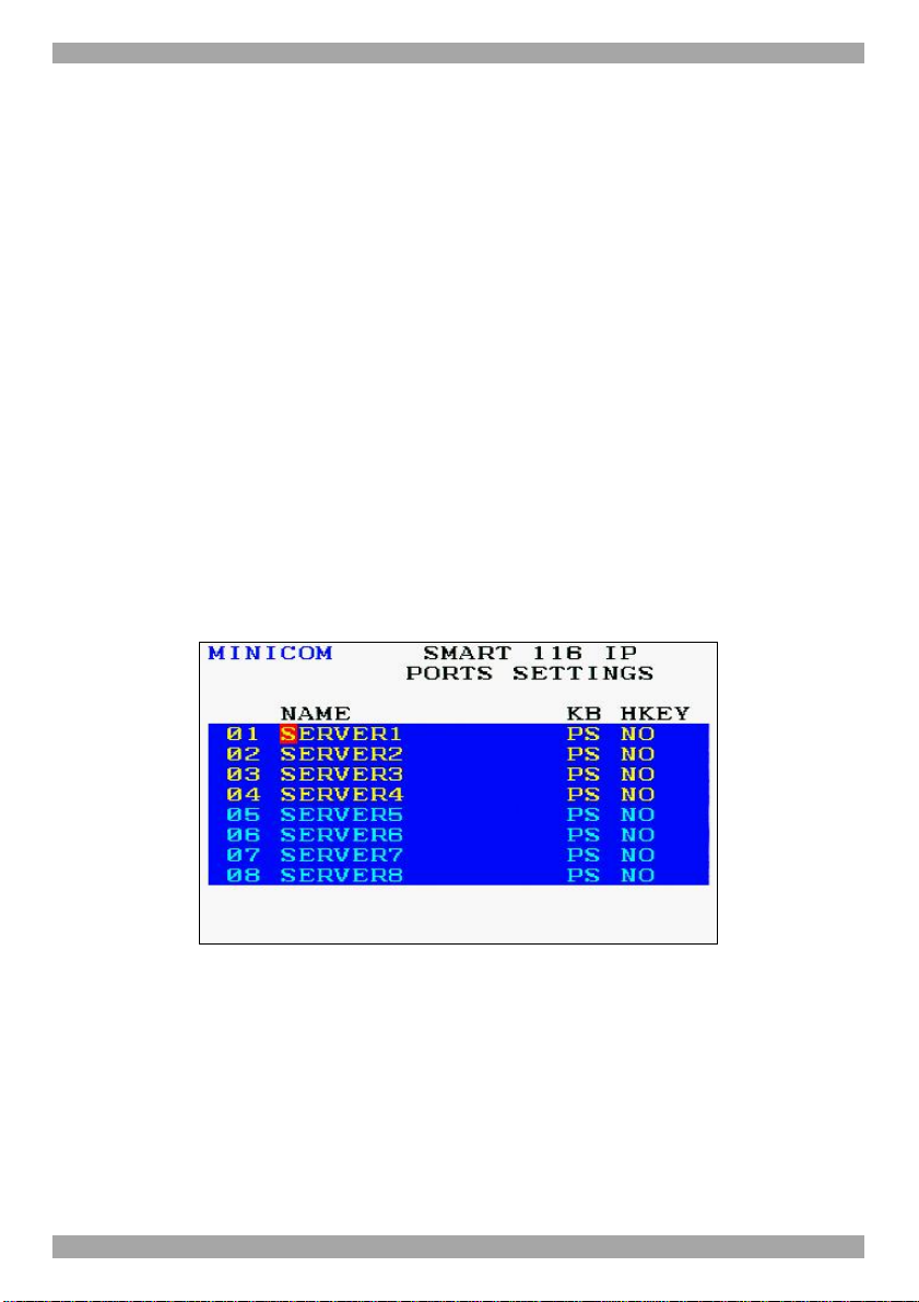
24.1.6 The Ports settings
From the General Settings, return to the Settings window by pressing Esc.
Navigate to the Ports line and press Enter. The Ports settings window appears see
Figure 54.
Figure 54 Ports Settings window
24.1.6.1 Editing the computer name
In this window you can edit the computer names with up to 15 characters.
To erase a character:
Select it and press the Spacebar. Blank spaces remain in place of the erased
character.
50
Page 52
SMARTRACK 116 IP
To erase an entire line:
Place the cursor at the beginning of the line. Keep the Spacebar depressed until the
line is erased.
24.1.6.2 Keyboard (KB)
By default the Keyboard mode is set to PS, which is suitable for Windows, Linux,
MAC OS, SUN Solaris and most other operating systems.
For certain UNIX operating systems set the KB column as follows:
• U1 for HP UX
• U2 for Alpha UNIX, SGI, Open VMS
• U3 for IBM AIX
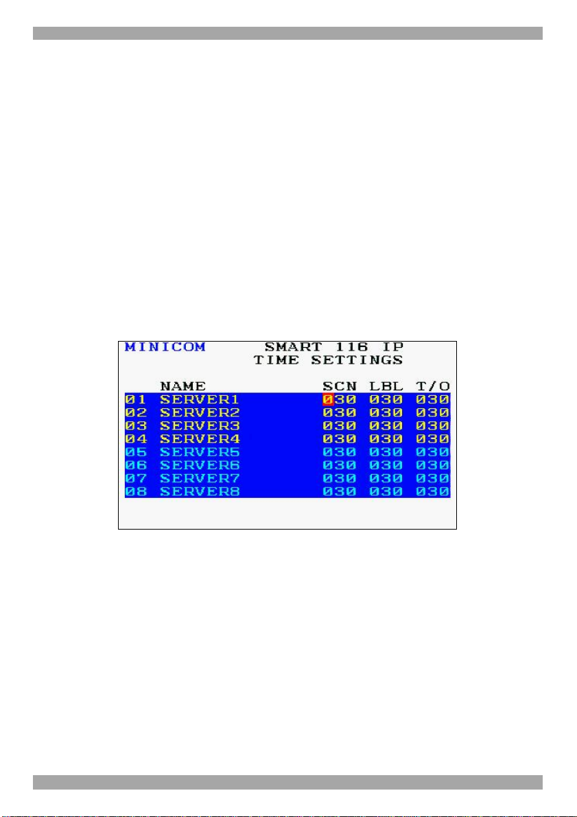
24.1.7 The Time settings
In the Settings window navigate to the Time line and press Enter. The Time
settings window appears see Figure 55.
Figure 55 Time settings window
24.1.7.1 Scan (SCN) - Label (LBL) - Time out (T/O)
SCN - In the SCN column, change the scan period.
LBL - In the LBL column, change the display period of the OSD label showing
which computer is currently accessed.
T/O - When password protection is activated you can automatically disable the
Management keyboard, mouse and screen after a preset time of non-use. Set this
Timeout period in the T/O column.
To set the above periods:
1. On the desired line press Tab to jump to the desired column.
51
Page 53
USER GUIDE
2. Place the cursor over one of the 3 digits and type a new number. Enter a leading
zero where necessary. For example, type 040 for 40 seconds.
Typing 999 in the LBL column displays the label continuously. Typing 000 –
the label will not appear.
Typing 999 in the T/O column disables the Timeout function. Warning! Typing
000 causes the Timeout function to work immediately. Minimum time should
be not less than 005 seconds.
Typing 999 in the SCN column displays the screen for 999 seconds. Typing 000
– the computer screen is skipped.
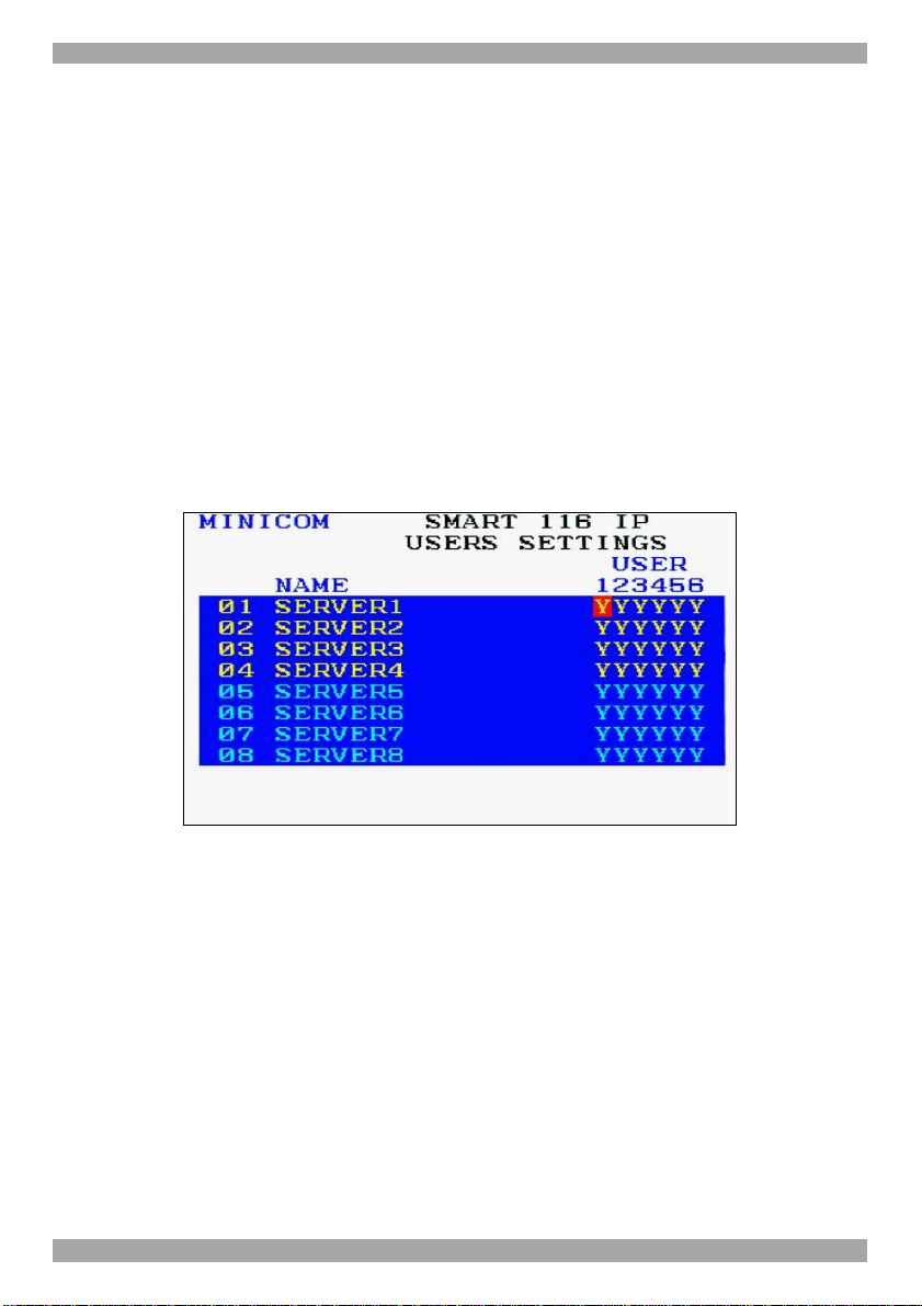
24.1.8 Users
In the Settings window navigate to the Users line and press Enter. (Note! Users is
only enabled if the security status is set to On, see page 49). The Users settings
window appears see Figure 56.
Figure 56 Users settings window
There are 3 different access levels. These are:
• Y – Full access to a particular computer. Plus access to the F4, F5 and F6
OSD functions
• V –Viewing access only, to a particular computer (No keyboard/mouse
functionality)
• N – No access to a particular computer – A TIMEOUT label appears if
access is attempted
To give each user the desired access level:
1. Navigate to the desired computer line and User.
2. Toggle between the options using the Spacebar.
52
Page 54
SMARTRACK 116 IP
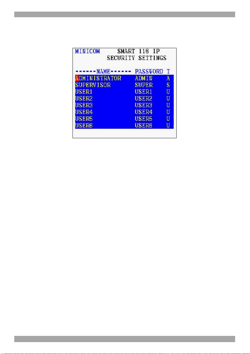
24.1.9 Security
In the Settings window navigate to the Security line and press Enter. The Security
settings window appears see Figure 57.
Figure 57 Security settings window
The ‘T’ column on the right hand side stands for Type of password.
There can only be 1 Administrator password, 1 Supervisor password, and 6 User
passwords.
To change a user name or password:
1. Navigate to the desired line and column.
2. Type a new user name / password. User authentication is done solely via the
password there is no security significance to the names.
By default the User Profile settings are full access.
24.1.10 The OSD HELP window – F1
To access the HELP window press F1. The HELP window appears see Figure 58.
53
Page 55

USER GUIDE
Figure 58 HELP window
Please note! All the functions set out in the Help window are performed from the
Main window. The Help window is merely a reminder of the hotkeys and their
functions.
24.1.11 Scanning computers– F4
Where necessary adjust the scan time in the Time Settings window, see above.
To activate scanning:
1. Press Shift twice to open the OSD.
2. Press F4. Your screen displays each active computer sequentially, with the Scan
label appearing in the top left corner.
To deactivate scanning:
Press F4.
24.1.12 Tuning – F5
You can tune the image of any remote computer screen from the Select Computer
window.
To adjust the screen image:
1. Navigate to the remote computer you wish to adjust.
2. Press F5. The screen image of the selected computer appears, together with the
Image Tuning label.
3. Adjust the image by using the Right and Left Arrow keys.
4. When the image is satisfactory, press Esc.
54
Page 56

SMARTRACK 116 IP
Note! Picture quality is relative to distance. The further away a remote computer is
from the SmartRack 116 IP, the lower the image quality, and the more tuning
needed. So place the higher resolution computers closer to the manager unit.
24.1.13 Moving the label – F6
Position the OSD label anywhere on the screen.
To position the label from the Main window:
1. Navigate to the desired computer using the Up and Down arrow keys.
2. Press F6. The selected screen image and Identification label appears.
3. Use the arrow keys to move the label to the desired position.
4. Press Esc to save and exit.
24.1.14 DDC – F10
Display Data Channel (DDC) is a VESA standard for communication between a
monitor and a video adapter.
Input the DDC information of the monitor connected to the SmartRack 116 IP
switch into the memories of all connected ROCs when first installing system.
To input the DDC information:
1. Press Shift twice to open the OSD.
2. Press F10. “Please wait” flashes a few times and disappears. The monitor’s
DDC information is sent to all ROCs.
24.1.14.1 Updating the DDC information
Update the DDC information in any of the following circumstances:
• When replacing the monitor connected to SmartRack 116 IP Switch
• When adding a new ROC to the system
• When reconnecting an existing ROC that was temporarily used in a
different system
To update the DDC information, repeat the steps as set out above.
55
Page 57

USER GUIDE
25. Upgrading the SmartRack 116 IP firmware
With the Update software program you can upgrade the firmware for the:
• 116 IP Switch
• ROCs
Update enables you to add new features and fix bugs in a quick and efficient
manner. Install the Update software on any computer, even one not part of the
SmartRack 116 IP system.
The Update software and the latest firmware for your system are located on our
website www.minicom.com in the Support section on the Smart CAT5 Switch
Upgrades page.
You can also manually update the ROCs as explained in section 25.4.4 on page 60.
25.1 System requirements for the SmartRack 116 IP Update software
• Pentium 166 or higher with 16 MB RAM and 10 MB free Hard Drive
space.
• Free Serial port.
• Windows 98 and later.
25.2 Connecting the SmartRack 116 IP system
To update the firmware, the SmartRack 116 IP system must be connected and
switched on.
25.3 Installing the software
Download the Update software from www.minicom.com and install it on your
computer.
25.3.1 Connecting the RS232 Download cable
To run the software, connect the RS232 Download cable to the computer
containing the Update software, and to the SmartRack 116 IP Switch. See Figure
59.
56
Page 58

SMARTRACK 116IP SWITCH
SMARTRACK 116 IP
MINICOM
To Flash
connector
FLASH LAN
SMARTRACK 116IP SWITCH
RS232 Download
cable
10 11 12 13 14 15 169
SERIAL
1 2 3 4 5 6 7 8
0
I
Update software
installed here
Figure 59 RS232 Download cable
M
O
C
I
N
I
M
ROCs
to servers
M
O
C
I
N
I
M
25.4 Starting and configuring the SmartRack 116 IP Update
1. Start the Update software by double-clicking the icon on your desktop ,
or choose Start/Programs/Smart CAT5 Switch Update/ Smart CAT5 Switch
Update. The Smart CAT5 Switch Update window appears. See Figure 60.
Where the ROCs do not appear, select Options/Get RICCs.
Smart 116 IP
Switch
RoC /
RICCs
Status bar
Figure 60 Update window
57
Page 59
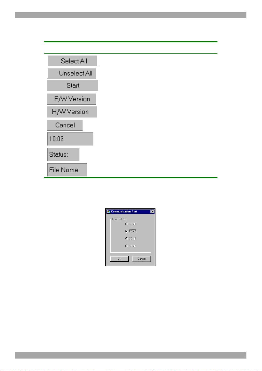
USER GUIDE
The table below explains the functions of the buttons and boxes in the SmartRack
116 IP Switch Update window.
Button or Box Function
Selects all RICCs
Unselects selected RICCs
Starts firmware download
Displays the firmware version number
Displays the hardware version number
Cancels selected function
System time
Displays download status
Name of Update file
2. To change the Com Port from the Options menu choose Com Port. The Com
Port Dialog box appears. See Figure 61.
Figure 61 Com Option box
3. Choose the Com Port the RS232 Download cable is connected to and click OK.
25.4.1 Verifying the version numbers
Before upgrading the firmware, you must first verify which firmware and hardware
versions you have.
25.4.1.1 OSD version number
To verify the OSD or Switch version number:
1. In the Update window, check the Manager Unit. See Figure 60.
58
Page 60

SMARTRACK 116 IP
2. Click . The version numbers appear in the Switch box.
3. Click . The switch hardware version number appears in the
Switch box.
25.4.1.2 ROC version number
To verify the RICC version number:
1. Before you can check a ROC, you must uncheck the Switch Unit box
options.
2. Check one or more or all of the ROCs.
3. Click . The firmware version number appears after the
ROC number.
4. Click . The hardware version number appears after the
ROC number.
When “Not responding” appears, there is no computer connected, or it is switched
off.
25.4.2 Obtaining new firmware
Download the latest firmware for your system from www.minicom.com.
25.4.3 Updating the firmware
Warning!
Never switch off any computer connected to the SmartRack 116 IP system during
the updating process.
To update the firmware:
1. Select the option to update SmartRack 116 IP switch or the ROCs.
2. From the File menu, choose Open. The Open box appears. See Figure 62.
3. Navigate to the folder that contains the firmware update file. You may only
see the files that match the file selection mask.
59
Page 61

USER GUIDE
Figure 62 Open box
4. Open the file.
5. Click Start. The SmartRack 116 IP Switch Update flashes the firmware. On
completion the firmware version number appears.
6. Check that the updated version number is correct by pressing
.
Firmware Update generates one log file per session that displays a chronological
list of actions. You can read the log file in any ASCII text editor. The log file is
located in the Windows directory.
25.4.4 Manually updating ROCs
After starting the Update software:
1. Select one or more ROCs.
2. Press Options -> Advanced -> Manual Update
3. Open the appropriate hex file.
4. Press Start. The firmware updates.
25.5 Troubleshooting the Update software
This section covers:
• Resetting the units
• Returning the OSD to the factory default settings
• Getting the current status
• Communication Error message
• Electricity failure
60
Page 62

SMARTRACK 116 IP
25.5.1 Resetting through the Update software
Reset the SmartRack 116 IP Manager or ROCs when for example the unit hangs or
when the mouse fails to work properly. Resetting is done via the Serial port, and
avoids the need to shut down the computer.
NOTE! The Reset function does not affect the parameters of the unit settings.
To reset the Switch or RICC units:
1. For the Switch, check the Manager Unit option.
For the ROCs, check one or more ROCs.
2. From the Options menu choose Advanced / Reset. The units reset. The system
should now be operational.
25.5.2 Setting default values for the OSD
To return the OSD to the factory default settings:
Select Options/Advanced/Set Default. A warning appears, click OK. The OSD
returns to the factory default settings.
25.5.3 Getting the current status
If there is a break in communication between the Update software and the system,
select Options/Get Status to get the current status of the computers in system.
25.5.4 Communication Error message
When using Firmware Update software you may sometimes get a Communication
Error message.
When updating a unit and a Communication Error message appears, do the
following:
1. Check that the RS232 Download cable’s RS232 connector is connected to
the Switch’s Communication port.
2. Check that the RS232 Download cable’s DB9F connector is connected to the
DB9M Serial port on the CPU’s rear panel.
3. Restart the download process.
25.5.5 Electricity failure
When the electricity fails while updating the SmartRack 116 IP firmware, do the
following:
If the electricity fails during the firmware update of the Switch, a Communication
Error message appears. Simply resume the firmware update by opening the folder
that contains the firmware update file and continue from there.
61
Page 63

USER GUIDE
If the electricity fails during the firmware update of the ROCs a Not Responding
or Upgrade Error message appears. Restart the upgrade from the beginning.
(For electricity failure during a firmware upgrade of the digital part of the
SmartRack 116 IP, see page 42).
62
Page 64

SMARTRACK 116 IP
26. Technical specifications
Target server
Operating systems
Resolution
Video and mouse synchronization Both auto and manual modes
Security 128-bit SSL encryption
Connections
Windows, Linux, UNIX and other major operating systems
Client computer
Windows 2000 or higher with IE 6.0 or higher and ActiveX
Target server
Up to 1280x1024@75Hz
Client computer
Recommended - resolution should be higher than on
Target Server
Ethernet – RJ45 – 10/100 Mbit/sec autosensing
Serial – RJ45
Local KVM connection – Screen HDD15,
Keyboard./Mouse – MiniDIN6
Flash – RJ11
Server – RJ45 x 16
Weight (Switch + console) 11.8kg / 26.01lbs
Shipping weight 17kg / 37.47lbs
Dimensions (Switch + console) 470.1 x 447.5 x 44mm / 18.5 x 17.6 x 1.7in
Power input 100 – 240 VAC, 0.8 A, 50 / 60 Hz.
Operating / Recommended ambient
temperature
Storage temperature - 20º - 40º C/-4º - 104ºF
Humidity 10%~90%RH
System cable CAT5 cables. FTP or UTP 2x4x24 AWG solid wire
Computer to switch distance Up to 30m/100ft.
Console display 17”
Panel type Active Matrix TFT LCD
Pixel pitch Supports 0.264mm
Viewing angle Right-Left view 60º -70 º. Up-Down view 45 º - 60
Contrast ratio 450:01:00
0ºC to 40ºC/32ºF to 104ºF
63
Page 65

USER GUIDE
Brightness White 250cd/m2
Back light Four lamps
Supported colors 16.7M
Keyboard / mouse 106 key PS/2 keyboard with touchpad
Sync 45~80HZ
Power source 100-240 VAC input
Response time Rising time 2-6ms Delay time 14-24ms
Rack depth support 468.9 to 814mm/18.46x32.047
Chassis construction Heavy duty steel
Power supply Internal switching 85-260 VAC 50 / 60 Hz
ROCs
Connections
VGA
Keyboard/Mouse
System
Power From computer’s
Product weight All ROCs 100g / 0.20lb
Shipping weight All ROCs 172g / 0.38lb
Dimensions All ROCs 65 x 25 x 25mm / 2.55 x 0.98 x 0.98”
ROC PS/2 ROC USB
HDD15
MiniDin6
RJ45
Keyboard port
HDD15
USB
RJ45
From USB port
64
Page 66

SMARTRACK 116 IP
27. Video resolution and refresh rates
Hz →
640x480 x x x x x
720x400 x
800x600 x x x x
1024x768 x x x x x
1152x864 x
1152x900 x
1280x720 x
1280x768 x x
1280x960 x
1280x1024 x x x
56 60 65 66 70 72 73 75
28. Safety
This device contains no serviceable parts. Any servicing of the device must be
performed by an authorized Minicom technician in a Minicom authorized Service
Center.
29. User guide feedback
Your feedback is very important to help us improve our documentation. Please
email any comments to: ug.comments@minicom.com
Please include the following information: Guide name, part number and version
number (as appears on the front cover).
30. WEEE compliance
WEEE Information for Minicom Customers and Recyclers
Under the Waste Electrical and Electronic Equipment (WEEE) Directive and
implementing regulations, when customers buy new electrical and electronic
equipment from Minicom they are entitled to:
• Send old equipment for recycling on a one-for-one, like-for-like basis (this
varies depending on the country)
• Send the new equipment back for recycling when this ultimately becomes
waste
Instructions to both customers and recyclers/treatment facilities wishing to obtain
disassembly information are provided in our website www.minicom.com.
65
Page 67

Germany
Kiel
Tel: + 49 431 668 7933
info.germany@minicom.com
USER GUIDE
Regional Offices
France
Vincennes
Tel: + 33 1 49 57 00 00
info.france@minicom.com
Italy
Rome
Tel: + 39 06 8209 7902
info.italy@minicom.com
England
Tel: + 44 121 288 0608
info.uk@minicom.com
China
Tel: +86 21 6445 3181
info.china@minicom.com
www.minicom.com
Asia Pacific / S. Korea
Tel: +972 2 535 9618
info.ap@minicom.com
66
 Loading...