

Page 1
DX User IP II - Quick Start Guide
1. Introduction
To take advantage of the DX User IP II full range of features, we recommend you
read the softcopy User Guide after performing the Quick Start procedure. It’s in
PDF format on the supplied CD or on our website www.minicom.com in the
Support section.
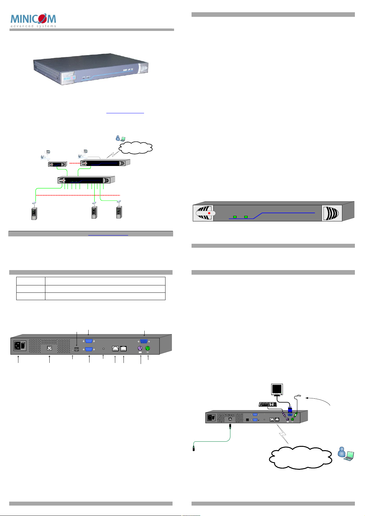
Figure 1 illustrates the basic configuration of the DX system with the DX User IP II
and DX Users connected to peripheral devices via the DX Central.
Remote
User
DXU-IP
Computer
Internet / VPN / LAN
II
X-RICC
Local
Local
User
MINICOM
DX User
DX 432 Central
1 32
X-RICC
Computer
User
MINICOM
Computer
SystemOKActivity
DX User IP II
DX432
Central
X-RICC
DX
Power
User
MINICOM
Power Link
To computers
Figure 1 DX User IP II usage scenario
Technical support - support@minicom.com
© 2009 Copyright Minicom Advanced Systems. All rights reserved.
5UM60000 V1.2 9/09
DX USER IP II
1.1 Standalone mode or KVM.net
DX User IP II can be used in any of the following 3 modes:
· Standalone
· KVM.net enabled
· KVM.net managed
KVM.net is a centralized IP based system for secure control of servers and network
devices, power and user administration in the data center environment. KVM.net
combines Out-Of-Band, KVM via IP access with modern IT standards and
requirements. It is the most comprehensive remote server maintenance solution
available in the market today.
These 3 modes are now explained.
1.1.1 Standalone mode
Standalone mode refers to using the DX User IP II as part of the DX system only
and working via the DX AIM interface without KVM.net, for remote KVM access
and control via a LAN or Internet connection.
1.1.2 KVM.net enabled / managed
The DX User IP II can be KVM.net enabled or KVM.net managed. Both of these
refer to managing and accessing servers connected to the DX system via the
KVM.net Manager.
KVM.net enabled means the DX is still capable of working in Standalone mode.
KVM.net managed means the DX is fully managed and controlled by KVM.net,
access to the AIM interface is blocked but can be achieved where necessary via
hotkeys. Details of the differences between KVM.net enabled and managed will be
explained in the configuration and operating sections later on in this Guide.
2. DX User IP II front panel
Figure 2 illustrates the DX User IP II front panel.
DXU - IP
MINICOM
System OKActivity
Figure 2 Front panel
The table below explains the functions of the front panel LEDs.
1
II
QUICK START GUIDE
LED Function
Activity LED solid when a remote user operates the DXU IP II
System OK LED solid when DX User IP II connected and functioning
2.1 DX User IP II rear panel
Figure 3 illustrates the rear panel of the DX User IP II.
RS232 Serial
USB
port
ports
www.m inico m.com
POWER
100-240 VAC 50/60 Hz
Power
connector
I
0
SYSTEM
CAT5 to DX
Central
DX Reset
button
SERIAL
USB TERMINAL
RS232
Terminal port
GO LOCK
Go Lock
button
SERIAL 2
Serial 2
port
ETHERNET
Ethernet
port
Figure 3 DX User IP II rear panel ports
DX Reset button
The DX Reset button resets the DX parts of the DX User IP II.
Go Lock button
The Go Lock button disconnects the active remote session and returns control to the
local user.
Serial / Serial 2 port
The Serial port is only used for KVM.net managed mode when the DX User IP II is
the Master Console – (explained in the softcopy User Guide).
In Standalone and KVM.net enable modes, the Serial 2 port can be used for any
RS232 application, e.g. managing a router or power switch.
Terminal port
In Standalone and KVM.net enable modes only, when there are X-RICC RS232s in
the DX system, you can control them locally through an RS232 terminal connected
to the DX User IP II.
Ethernet - Connects the DX User IP II to an Ethernet network.
Monitor
USER
Mouse
Keyboard
DX USER IP II
USB ports
Update the DXU firmware via a Minicom Flash USB key. See the DX User Guide
for information on updating firmware.
System port – Used to connect the DX User IP II to the DX Central.
KVM ports – Used for optional local console.
3. Pre-installation guidelines
· Place cables away from fluorescent lights, air conditioners, and machines that
are likely to generate electrical noise
· The maximum distance between each device (computer, KVM switch or second
level DX Central) and the DX Central is 100m/330ft. The maximum distance
between the DX Central and the DX User IP II is also 100m/330ft. For best
performance place the DXU IP II as close as possible to the DX Central.
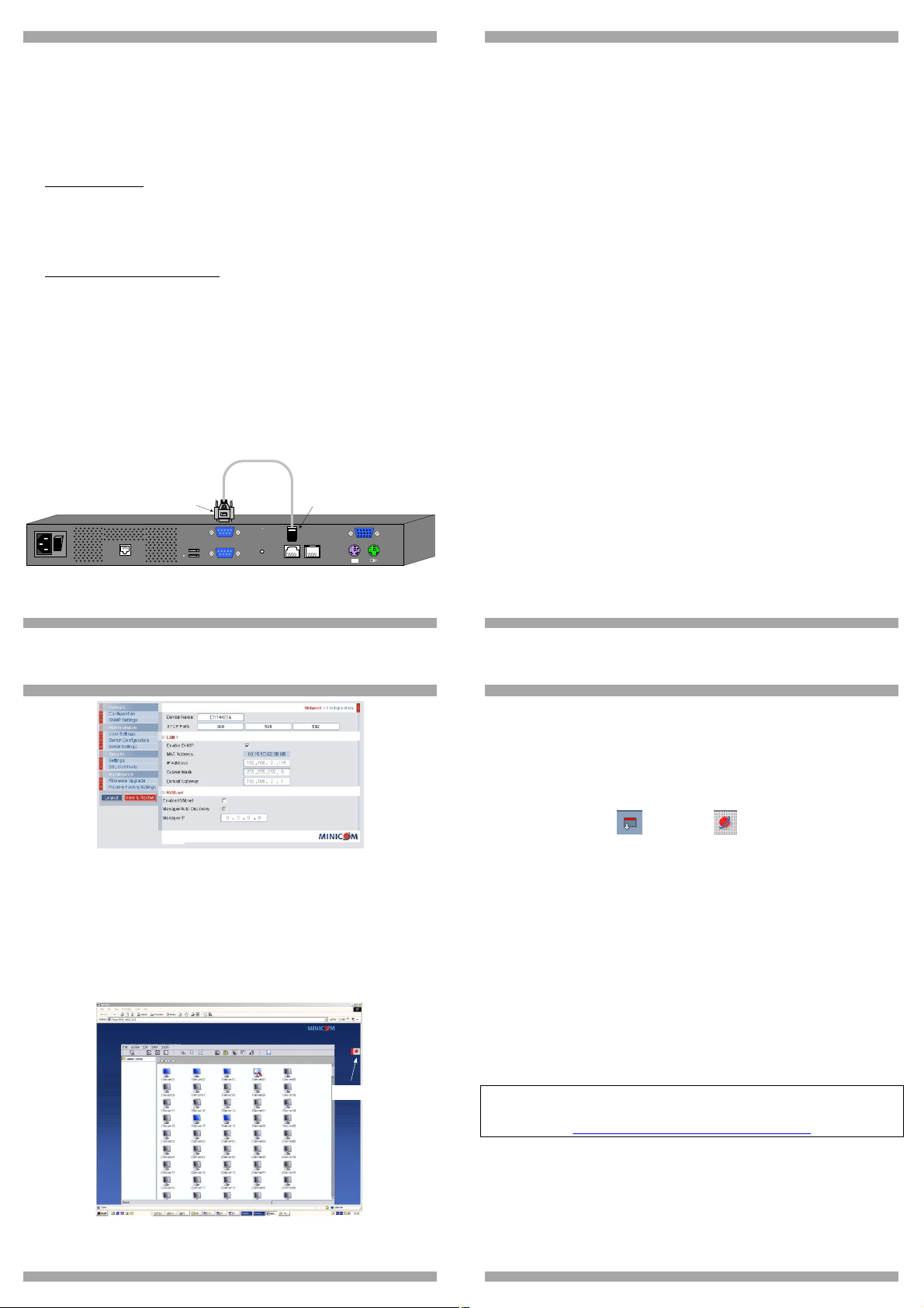
4. Connecting the DX User IP II
Figure 4 below illustrates the connections of the DX User IP to the DX system. See
below for more details.
www.minicom.com
I
0
CAT5
cable
SYSTEM
100-240 VAC 50/60 Hz
To DX Central
User port
POWER
SERIAL
USB TERMINAL
GO LOCK
Figure 4 DX User IP connections
SD
P110
USER
ETHERNET
SERIAL 2
Internet / VPN / LAN
(Optional)
Local
User
console
Remote user
2
3
Page 2
QUICK START GUIDE
4.1 Connecting the DX User IP to the WAN/LAN
The Ethernet connector on the DX User IP II can be used either for a 100 Mbps
100BASE-TX connection or for a 10 Mbps 10BASE-T connection. The adapter
adjusts to the appropriate operation mode automatically.
To connect to a LAN/WAN, connect an Ethernet cable to the DX User IP II Ethernet
port and the Network switch.
4.2 Connecting the DX User IP II to the DX Central unit
For KVM.net managed mode connect a CAT5 cable to the DX User IP II System
port and to DX Central User port 1. This DX User IP II must be assigned as the
Master Console – (explained in the softcopy User Guide). Where there are more
than one IP devices in the DX system, (e.g. DX User IP II units or IP Access
connected to a DX User unit etc), one of them must be connected to User port 1 of
the DX Central. The others can be connected to any other User port number.
For Standalone and KVM.net enabled modes connect a CAT5 cable to the DX
User IP II System port and to any DX Central User port.
4.3 Local User
To use the DX User IP II locally, connect a keyboard, video and mouse, as
illustrated in Figure 4.
4.4 Serial cable - KVM.net managed mode only
The Serial cable is only used when this DX User IP II is assigned to be the Master
Console in KVM.net managed mode (explained in the softcopy User Guide). Note!
The Master Console IP device must be connected to User Port 1 of the DX Central
unit.
Connect the Serial cable as illustrated below.
www.m inico m.com
POWER
100-240 VAC 50/60 Hz
To
Serial
port
I
0
SYSTEM
USB TERMINAL
Figure 5 Serial cable
Serial
cable
SERIAL
GO LOCK
SERIAL 2
To
Serial 2
port
ETHERNET
USER
DX USER IP II
4.4.1 Order of powering on
Connect the DX User IP to the power supply using the power cord provided.
The devices and servers can be powered on at any time. Power on the DX
components in the following order:
1. The DX Central.
2. The DX User IP II unit.
5. Configuring the system – web interface
How exactly to configure the system depends on how the DX User IP II is being
used. There are 3 possible options - Standalone, KVM.net enabled or KVM.net
managed. Explained in the softcopy User Guide.
5.1 Initial settings - Default IP address
By default, DXU IP II boots with an automatically assigned IP address from a
DHCP (Dynamic Host Configuration Protocol) server on the network. The DHCP
server provides a valid IP address, gateway address and subnet mask.
To identify the IP address, the DXU IP II MAC address appears on the underside of
the DXU IP II box. The device number (D.N.) can also be found there.
If no DHCP server is found on the network, DXU IP II boots with the static IP
address:192.168.0.155.
Note! If a DHCP server later becomes available, the unit picks up the IP settings
from DHCP server. To keep the static IP address, disable DHCP – explained in the
softcopy User Guide.
5.2 Logging into the Web interface
Complete the initial setup via the Web configuration interface:
1. Open your Web browser (Internet Explorer version 6.0 or higher).
2. Type the DXU IP II system IP address - https://IP address/config - and press
Enter.
3. Type the default Administrator user name - admin - and password - access (both lower case).
4. Press Enter. The Web interface opens at the Network Configuration page. See
Figure 6.
4
QUICK START GUIDE
Figure 6 DXU IP II Web interface
Consult your Network Administrator for the network settings. See the
softcopy User Guide for more information on configuring the system.
6. Operating the system
From a remote computer console open Internet Explorer (6.0 and above) and type
the DXU IP II’s IP address. https://IP address. The DX Login page appears. Type
the username and password and press Enter. By default, the user name is: admin
and the password is admin, (both lower case). The DX AIM appears, see Figure 7.
Login to AIM and use the IP toolbar for switching between the servers.
IP toolbar
5
DX USER IP II
6.1.1 Accessing a server/device
To connect to a server/device:
Important!
Accessing or switching to the servers from the IP toolbar, only works when the DX
AIM is on the Servers/Devices page, see Figure 7.
1. Select View/Servers/Devices to display the Servers/Devices page.
2. From the Toolbar, click , or right-click . A list of connected
servers/devices the user has permission to access appears. Note! These are the
server names as configured in the IP interface and not the DX AIM interface – we
recommend giving the servers the same names in both the IP and DX portions.
3. Click the desired server or Serial device. The screen of the server or the Serial
device window appears..
4. To switch to a different server repeat steps 1 and 2 above.
5. To display the DX AIM press the left Shift key twice.
6. On logging out and then logging in again, the screen of the last accessed
server/device appears.
6.2 Accessing servers/devices via KVM.net
When the DX User IP II is in KVM.net enabled and managed modes: From the
KVM.net GUI, Targets are accessed from the My Targets folder. See the KVM.net
User Guide for further details. Note! Only permitted Targets appear in the list.
For the rest of the configuration and operating instructions please see the softcopy
User Guide on the supplied CD or on our website
http://www.minicom.com/supportuserguides.htm
Figure 7 Servers page
When access is via IP, you should not switch to the servers/devices using the DX
AIM, but only via the IP toolbar, see Figure 7.
6
7
 Loading...