

Page 1
CAT5 Video Display
Quick Installation Guide
International HQ
Jerusalem, Israel
Tel: + 972 2 535 9666
[email protected]
www.minicom.com
North American HQ
Linden, New Jersey
Tel: + 1 908 4862100
[email protected]
Customer support - [email protected]
European HQ
Dübendorf, Switzerland
Tel: + 41 1 823 8000
[email protected]
5UM40092 V3.3 8/05
Page 2

CAT5 VIDEO DISPLAY
1. What is the CAT5 Video Display system?
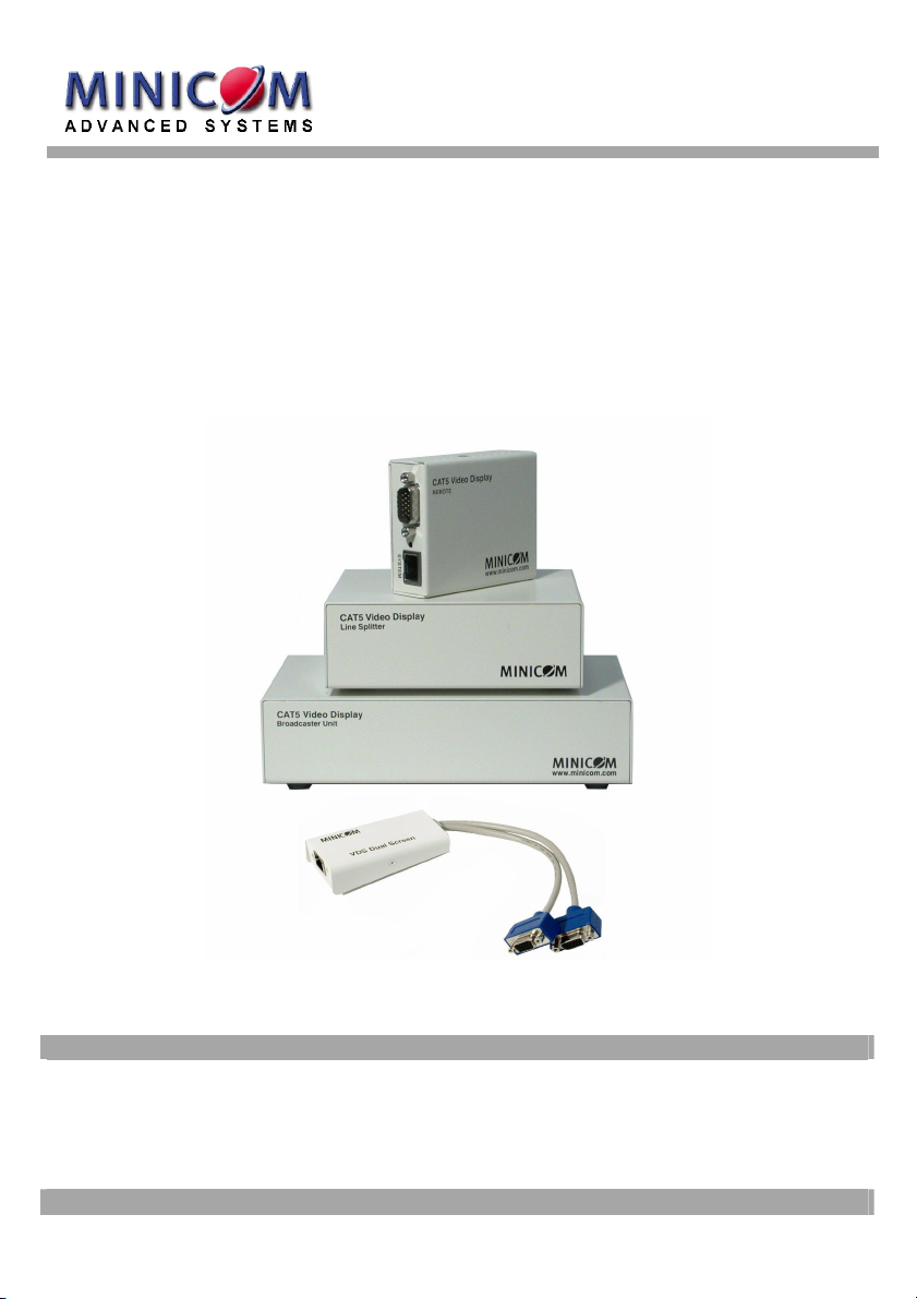
The CAT5 Video Display (VDS) system from Minicom broadcasts real-time highresolution video signals to hundreds of remote display monitors.
The VDS system consists of the following:
• Broadcaster + Control Unit
• Line Splitters to expand the system
• Remote units that connect to each remote monitor/computer
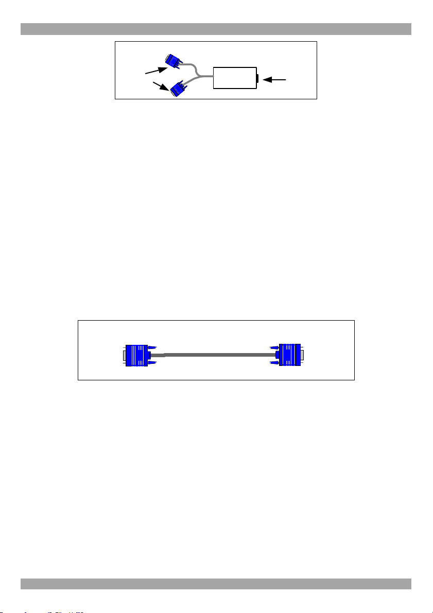
• Remote Dual Screen connects 2 monitors to the system
CAT5 UTP or FTP cables connect the VDS system. The Remote units can be up to
110m/360ft away from the Broadcaster.
This Quick Installation Guide illustrates the VDS system and explains how to
install and operate it.
2. The multi-functional VDS system
You can use the VDS system in the following ways:
(A) Without the Control Unit
The VDS system constantly broadcasts a computer screen to all remote
monitors.
(B) With the Control Unit
• Broadcast a computer screen to all remote monitors
• Darken all remote screens
• Release the remote screens to allow local monitor viewing (when remote
computers are connected).
The screen dark function is useful when carrying out maintenance, changing
the broadcast program or in a classroom environment to grab students’
attention.
With both applications broadcast the video up to resolutions of 1600 x 1200 @
75Hz depending on the cable length.
1
Page 3
QUICK INSTALLATION GUIDE
3. The VDS units
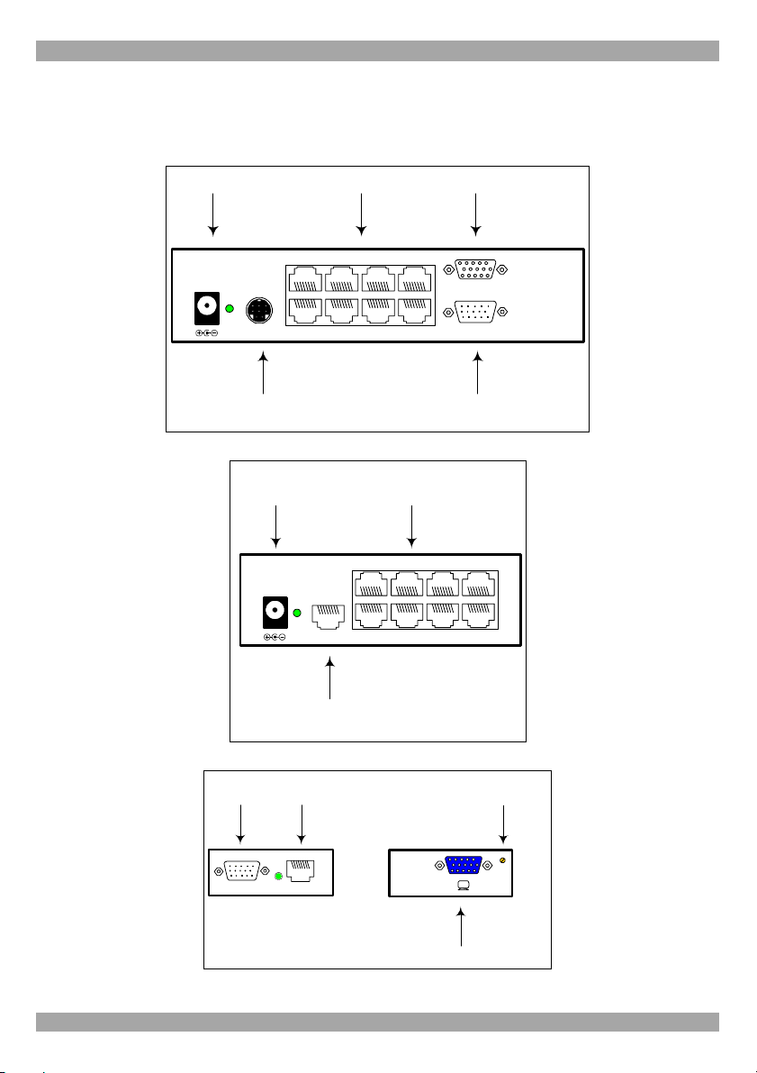
The figures below illustrate the Broadcaster Unit, Line Splitter, Remote units and
Remote Dual Screen.
Power connector
12VDC
CONTROL
VDS Control Unit
Power
connector
12VDC
System cables Monitor
SYSTEM
Broadcaster Unit
System cables
SYSTEM OUT
SYSTEM IN
VIDEO OUT
VIDEO IN
Video
cable
www.minicom.com
System cable from Broadcaster or
previous Line Splitter
Line Splitter
Video
cable
VIDEO IN
System
cable
SYSTEM
Side A
Remote unit
Picture adjuster
PICTURE
Side B
Monitor
2
Page 4
CAT5 VIDEO DISPLAY
VDS Remote
Dual Screen
To
monitors
Remote Dual Screen
System
cable
4. Expanding the VDS system
You can expand the VDS system to 512 Remote units by having 2 levels of Line
Splitters. Level 1 Line Splitters can have 8 Remote units or Line Splitters
connected. Level 2 Line Splitters can have 8 Remote units connected. (See page 4).
5. Pre-installation instructions
Note! In the VDS system the CAT5 UTP or FTP cables carry electrical power.
Therefore do NOT connect them to any other device. To avoid this we recommend
you attach the stickers provided to the ends of each cable.
Place cables away from fluorescent lights, air conditioners, and machines that are
likely to generate electrical noise.
6. The VDS cables
The Video cable is illustrated below. Connect the cable as explained.
To
Computer’ s
Video card
Broadcaster & Remote Video cable
To
Broadcaster ’s
or Remotes’
Video In por t
The Remote Video cable
The Remote Video cable is only used with the Remote unit when the Dongle is
connected to a computer.
Connecting the CAT5 cables
Please note! Connect the CAT5 cables to the Broadcaster and Line Splitter units
when the units are powered off. We recommend that you connect the CAT5 cables
BEFORE connecting the power supply.
Power supply
Connect the Broadcaster and Line Splitters to the power supply with the 12 VDC,
2A from the AC/DC adapter provided. The Remote units and the Remote Dual
Screen receive 12 VDC, 160 mA via the CAT5 cables from the Broadcaster or Line
Splitter.
3
Page 5

QUICK INSTALLATION GUIDE
7. The VDS configuration for a CBT application
The figure below illustrates the VDS configuration with the VDS Control Unit and
the optional remote computers. The Remote Dual Screen has no VGA input and is
therefore not suitable for CBT applications.
VDS Control Unit
Broadcaster Unit
CAT5 cables to
Remotes or Line
Splitters
Video cable
Broadcaster
computer
Video cable
Level 1
Level 2
CAT5 cables to
Remotes or Line
Splitters
Line
Splitter
CAT5 cables to
Remotes
Line
Splitter
CAT5 cables to
Remotes
Remote
Remote
Remote
Remote
computer
Video cable
Remote
computer
Video cable
Remote
computer
4
Page 6
CAT5 VIDEO DISPLAY
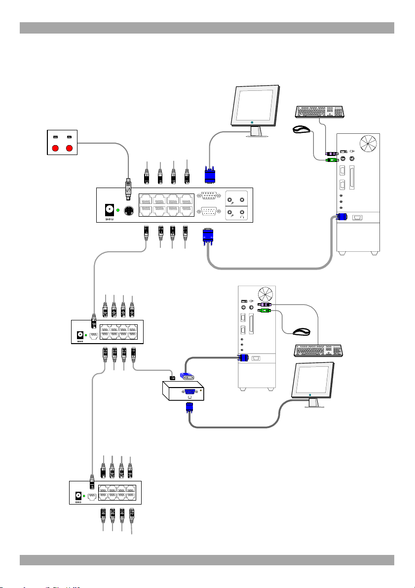
8. VDS detailed connections
The figure below illustrates the detailed connections of the VDS units.
Control Unit
VDS Control Unit
Master
Dark
to all
all
MINICOM
Broadcaster
Unit
12VDC
CAT5 cables to
Remotes or Line
Splitters
CONTROL
CAT5 cables to
Remotes or Line
Splitters
SYSTEM
CAT5 cables to
Remotes or Line
Splitters
VIDEO OUT
VIDEO IN
Sound Card
Headset
www.minico m.com
Speaker
Video cable
Broadcaster
computer
Line
Splitter
Line
Splitter
12VDC
12VDC
SYSTEM IN
SYSTEM IN
SYSTEM OUT
CAT5 cables to
Remotes or Line
Splitters
CAT5 cables to
Remotes
SYSTEM OUT
CAT5 cables to
Remotes
www.minicom.com
Video cable
Remote
PICTURE
www.minicom.com
Remote
computer
5
Page 7
QUICK INSTALLATION GUIDE
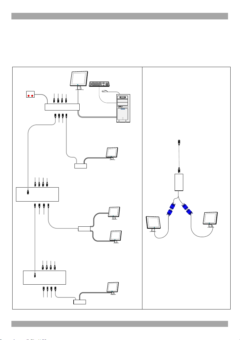
9. The VDS configuration without remote computers
The figure below illustrates the VDS configuration without optional computers
connected to the Remote units and the Remote Dual Screen. Connect the Broadcaster
and Line Splitters as in the figure on page 5. The figure on page 7 illustrates the
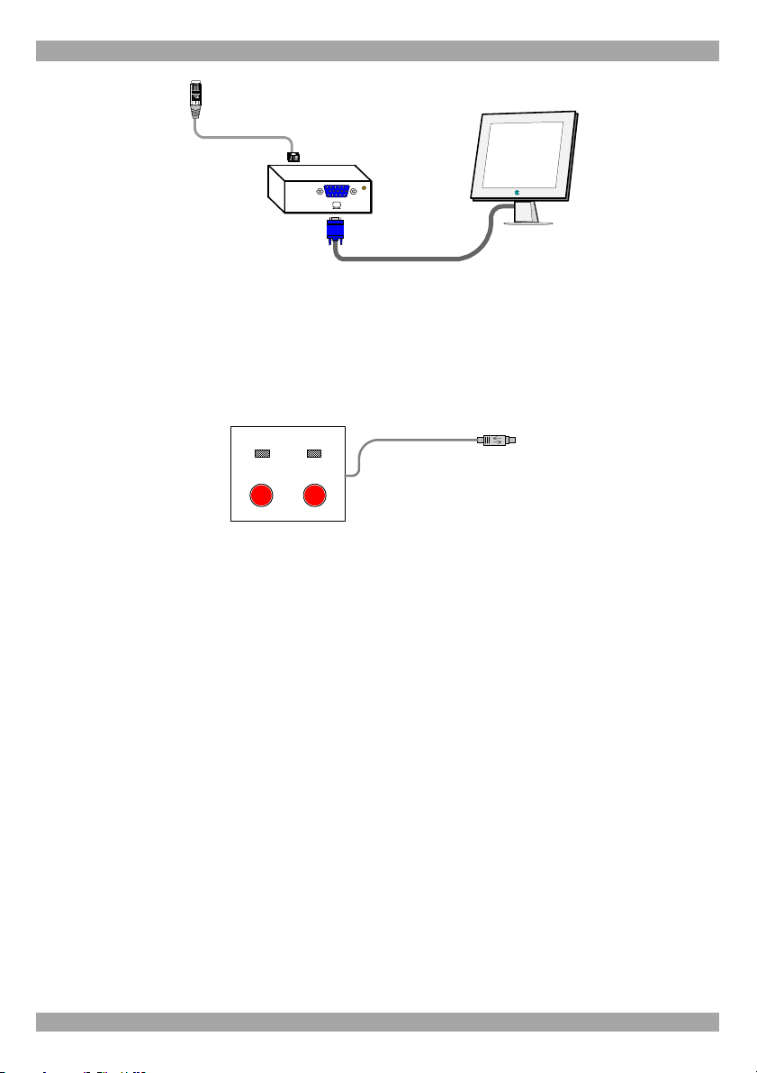
detailed connections of the Remote unit.
Remote Dual Screen
VDS Control Unit
CAT5 cables to
Remotes or Line
Splitter s
Broadcaster Unit
Video cable
Broadcaster
computer
Instead of the Remote unit, use
the Remote Dual Screen to
connect 2 screens to the
Broadcaster or Line Splitter via
CAT5 cable. The 2 screens
display the images broadcast by
the Broadcaster computer.
CAT5 cable to
Broadcaster or
Line Splitter
CAT5 cables to
Remotes or Line
Splitters
Line
Splitter
Remote
VDS Remote
Dual Screen
VDS
Remote
Dual Screen
CAT5 cables to
Remotes
Line
Splitter
Remote
6
Page 8
CAT5 VIDEO DISPLAY
CAT5 cable to
Broadcaster or
Line Splitter
Remote
PICTURE
10. Operating the VDS system
Once connected the VDS system broadcasts to all remote monitors.
The VDS Control Unit
The VDS Control Unit is illustrated below.
VDS Control Unit
To Broadcaster Unit’s
Master
to all
Dark
all
Control port
MINICOM
With the VDS Control Unit carry out the following functions:
Master to all
Press the Master to all button to send the broadcaster’s screen to all remote
monitors. The LED above the button lights up.
Press the button again to release the remote monitors.
Dark all
Press the Dark all button to darken all remote screens. The LED above the button
lights up.
Press the button again to release the remote screens.
11. Adjusting the picture quality
Use a small screwdriver to turn the Picture adjuster on the Remote unit to adjust the
picture quality.
7
Page 9
QUICK INSTALLATION GUIDE
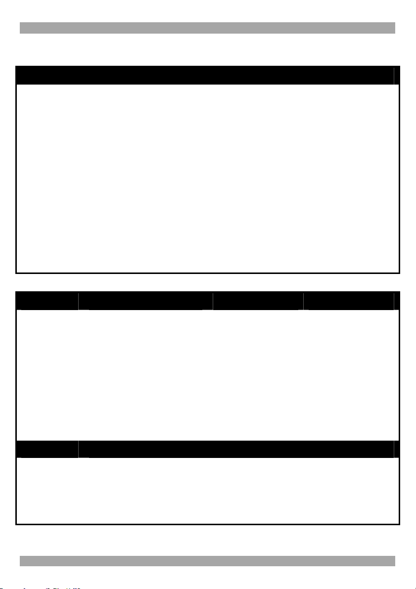
12. Technical specifications
SYSTEM
Resolution
System cable
Max distance
Input/Output Video Signals
Sync.
Horizontal/Vertical Sync.
Up to 1600x1200 @ 75 Hz
CAT5 UTP or FTP 2x4x24 AWG Solid Wire Conductor
cable
110m/360ft
Analog signal red, green, blue 0.7v p-p 75 Ohm
TTL compatible
Positive/Negative
Polarity
Operating temperature
Storage temperature
Humidity
Warranty
0ºC to 40ºC/32ºF to 104ºF
-40ºC to 70ºC/-40ºC to 158ºF
80% non condensing relative humidity
3 Years
BROADCASTER LINE SPLITTER REMOTE
Cables &
Connectors
Dimensions
Power
supply
VGA In - HDD15M
VGA Out - HDD15F
System Out - 8 Ports RJ45
Control - MiniDin8F
175 x 96 x 42mm/
0.57 x 0.38 x 0.14ft
External Power Adapter
12VDC 2A
System In - RJ45
System Out - RJ45
118 x 96 x 42mm/
0.39 x 0.38 x 0.14ft
External Power
Adapter 12VDC 2A
System In - RJ45
CPU VGA - HDD15M
Screen - HDD15F
78 x 62 x 23mm/
0.31 x 0.26 x 0.07ft
From previous unit
through CAT5 cable
REMOTE DUAL SCREEN
Cables &
Connectors
Power
supply
System In - RJ45
Screen x 2 - HDD15F
From previous unit through
CAT5 cable
8
 Loading...