

Page 1
www.minicom.com
International HQ
Jerusalem, Israel
Tel: + 972 2 535 9666
[email protected]
North American HQ
Linden, NJ, USA
Tel: + 1 908 486 2100
[email protected]
Customer support - [email protected]
5UM20094 V1.8 4/09
Universal Phantom Manager
Quick Installation Guide
UNIVERSAL PHANTOM MANAGER
1
1. What is the Phantom system?
The Phantom system from Minicom is a distributed KVM switching solution for 1
or more users. In the 1-User system a Manager controls the remote computers that
are connected to Phantom Remote units. The Remote units can be either PCI cards
or boxes called Specters. For multi-user functionality add a Phantom MX II.
The Phantom system supports mixed type and multi-platform computers.
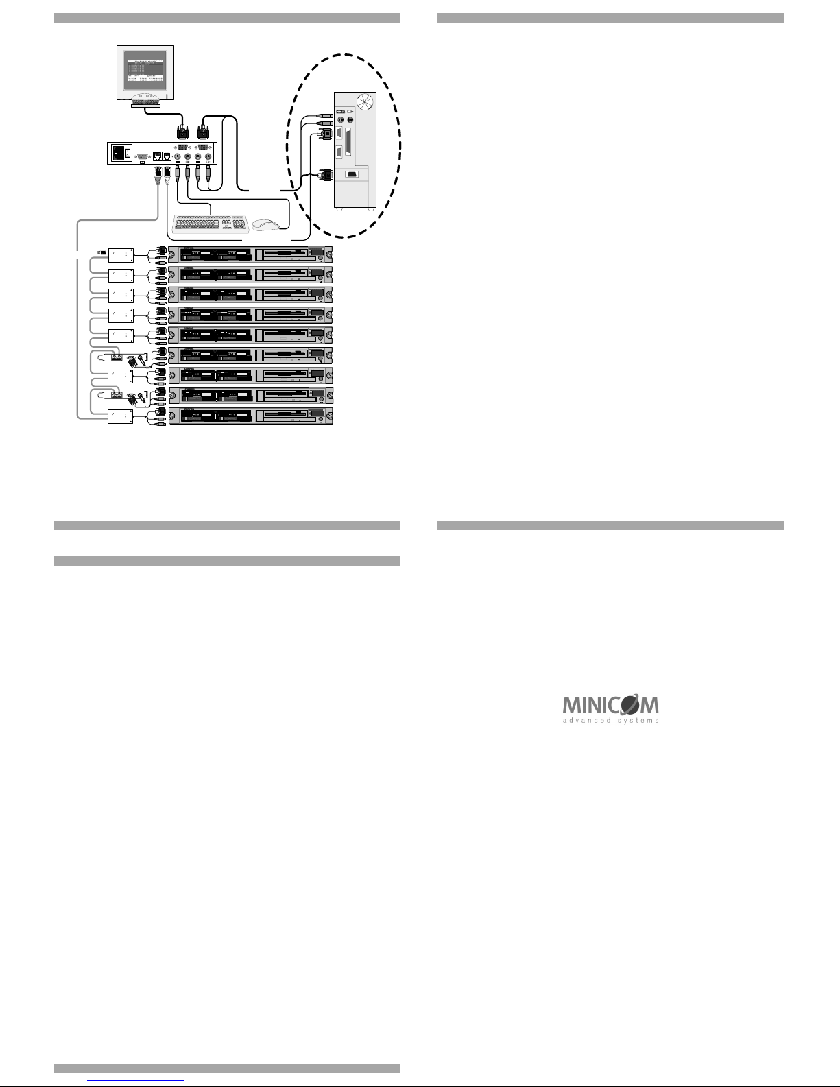
In the 1-User system, shielded CAT5 FTP cables connect the Phantom Manager to
the nearest Remote, and that Remote to the next one, and so on, in a daisy chain
pattern. The last Remote can be up to 110m/360ft away from the Manager. See the
configuration diagram on page 4 showing both Remote PCI cards and Specters in
the Phantom system.
The Multi-User system connects in a loop – as explained in Phantom MX II guide.
This Quick Installation Guide illustrates the Universal Phantom Manager (UPM)
and explains how to install it. For further information please see the softcopy Guide
on the Marketing & Documentation CD.
2. Connecting a computer to the UPM
To run the Phantom system the UPM does not need to be connected to a computer.
A computer must be connected to the UPM to perform Phantom applications such
as upgrading firmware or renumbering Remote units. This is discussed in detail in
softcopy User Guide.
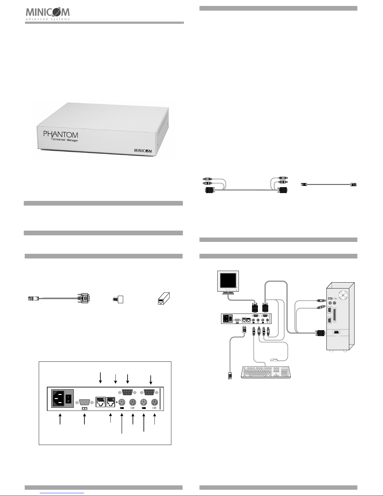
When you do connect a computer use the 3 in 1 CPU cable illustrated below.
3. The UPM cables
The cables below connect to the UPM.
Shielded CAT5 FTP cable
(Supplied with the Remote units)
3 in 1 CPU cable
4. Rack mounting
The UPM is rack mountable. To obtain a 19” bracket, order P/N 5AC00202.
QUICK INSTALLATION GUIDE
2
5. UPM accessories
The accessories below are explained fully in the softcopy Guide.
RS232 serial cable -
For Phantom applications
In Line Coupler -
To bypass Remote units
Terminator -
Connects to last Remote in daisy chain
6. Pre-installation instructions
Disconnect all computers from the electrical power supply.
Cables should be placed away from fluorescent lights, air conditioners, and
machines that are likely to generate electrical noise. Caution: For continued
protection against risk of fire, replace with the same type and rating of fuse only.
7. Connecting the UPM
The figure below illustrates the rear of the UPM.
Mouse
In port
Terminal
port
System
Out port
RS232
port
Power
LED
Power
connector
www.minicom.com
USER COMPUTER
SYSTEM SERVICEPOWER
85-265VAC 50/60 Hz
Keyboard
Out port
Mouse
Out port
Keyboard
In port
Video
In port
Video
Out port
Connect a keyboard, monitor, mouse plus the 3 in 1 CPU cable and Power cord to
the UPM and computer as illustrated in the figure below. Connect the Power cord.
Only use the power cord supplied with the UPM.
Note! Connecting a computer and the 3 in 1 CPU cable is optional.
UNIVERSAL PHANTOM MANAGER
3
To computer's
Keyboard port
To computer's
Mouse port
To
computer's
Video port
3 in 1 CPU cable
SD
P110
www.minicom.com
USER COMPUTER
SYSTEM SERVICEPOWER
85-265VAC 50/60 Hz
To
System
port
To Phantom Remote
System In port
Shielded CAT5
FTP cable
UPM
8. The Terminal port
When using RS232 servers in the system, you have the option of operating these
servers through the computer’s Terminal emulation or through an optional terminal
connected to the Terminal port.
9. What happens next?
Install the Phantom Remotes as explained in The Phantom Remote – Quick
Installation Guide. Give the Remotes ID numbers and configure keyboard settings
explained in the Read This First (RTF). The Phantom system is then ready for use.
Page 2
QUICK INSTALLATION GUIDE
4
CAT5 cable
ProLiant DL360
9.1 - GB
10k
ULTRA2 SCSI
9.1 - GB
10k
ULTRA2 SCSI
ProLiant DL360
9.1 - GB
10k
ULTRA2 SCSI
9.1 - GB
10k
ULTRA2 SCSI
ProLiant DL360
9.1 - GB
10k
ULTRA2 SCSI
9.1 - GB
10k
ULTRA2 SCSI
ProLiant DL360
9.1 - GB
10k
ULTRA2 SCSI
9.1 - GB
10k
ULTRA2 SCSI
ProLiant DL360
9.1 - GB
10k
ULTRA2 SCSI
9.1 - GB
10k
ULTRA2 SCSI
ProLiant DL360
9.1 - GB
10k
ULTRA2 SCSI
9.1 - GB
10k
ULTRA2 SCSI
www.minicom. com
USER COMPUTER
SYSTEM SERVICEPOWER
85-265VAC50/60 H z
Link
Active
MINICOM
www.minicom.com
PHANTOM
Specter
Link
Active
MINICOM
www.minicom.com
PHANTOM
Specter
Link
Active
MINICOM
www.minicom.com
PHANTOM
Specter
Link
Active
MINICOM
www.minicom.com
PHANTOM
Specter
Link
Active
MINICOM
www.minicom.com
PHANTOM
Specter
3in1Cable
SD
P110
RS232 Serial Cable
Optional
ProLiant DL360
9.1 - GB
10k
ULTRA2 SCSI
9.1 - GB
10k
ULTRA2 SCSI
ProLiant DL360
9.1 - GB
10k
ULTRA2 SCSI
9.1 - GB
10k
ULTRA2 SCSI
ProLiant DL360
9.1 - GB
10k
ULTRA2 SCSI
9.1 - GB
10k
ULTRA2 SCSI
Link
Active
MINICOM
www.minicom.com
PHANTOM
Specter
Link
Active
MINICOM
www.minicom.com
PHANTOM
Specter
OUT
IN
OUT
IN
UPM
The Phantom system configur ation
UNIVERSAL PHANTOM MANAGER
5
10. USB / SUN Combo keys
The PS/2 keyboard connected to the Phantom Manager does not have a special SUN
keypad to perform special functions in the SUN Operating System environment. So
when a Specter USB or SUN is connected to a SUN computer, the Specters emulate
these SUN keys using a set of key combinations called Combo keys. See the table
below.
SUN key Combo key
Stop
Left Ctrl + Left Alt + F1
Props
Left Ctrl + Left Alt + F3
Front
Left Ctrl + Left Alt + F5
Open
Left Ctrl + Left Alt +F7
Find
Left Ctrl + Left Alt + F9
Again
Left Ctrl + Left Alt + F2
Undo
Left Ctrl + Left Alt + F4
Copy
Left Ctrl + Left Alt + F6
Paste
Left Ctrl + Left Alt + F8
Cut
Left Ctrl + Left Alt + F10
Help
Left Ctrl + Left Alt + F11
Compose
Application key or Left Ctrl + Left Alt +
Keypad *
Crescent
Scroll Lock
Volume Up
Left Ctrl + Left Alt + Keypad –
Volume Down
Left
Ctrl + Left Alt + Keypad +
Mute
Left Ctrl + Left Alt + F12
Sun Left ◊ key
Left Windows key
Sun Right ◊ key
Right Windows key
Alt-Graph
Right Alt or Alt Gr
Stop A
Left Ctrl + Left Alt +1
QUICK INSTALLATION GUIDE
6
11. User guide feedback
Your feedback is very important to help us improve our documentation. Please email
any comments to: [email protected]
Please include the following information: Guide name, part number and version
number (as appears on the front cover).
12. WEEE compliance
WEEE Information for Minicom Customers and Recyclers
Under the Waste Electrical and Electronic Equipment (WEEE) Directive and
implementing regulations, when customers buy new electrical and electronic
equipment from Minicom they are entitled to:
• Send old equipment for recycling on a one-for-one, like-for-like basis (this
varies depending on the country)
• Send the new equipment back for recycling when this ultimately becomes
waste
Instructions to both customers and recyclers/treatment facilities wishing to obtain
disassembly information are provided in our website www.minicom.com.
2009 © Copyright Minicom Advanced Systems
UNIVERSAL PHANTOM MANAGER
7
 Loading...