

Page 1
International HQ
Jerusalem, Israel
Tel: + 972 2 535 9666
[email protected]
North American HQ
Linden, New Jersey
Tel: + 1 908 4862100
[email protected]
German Europe
Zurich, Switzerland
Tel: + 41 1 455 6220
[email protected]
Italy
Rome
Tel: + 39 06 8209 7902
[email protected]
www.minicom.com Customer support - [email protected]
V1.5 3/03
Phantom Operating Guide
Page 2

Introduction
1-1
Chapter 1: Introduction
The Phantom system from Minicom is a CAT5 based Distributed KVM Switching system for server
management. Connect up to 64 computers in the Phantom system. The system can be managed and controlled by
1 or 2 users. For 2-user control see the MX II Guide.
The Phantom system components
The Phantom system consists of:
• Management unit
• Remote units
• Cables and accessories – explained in the Installation guide
• Marketing & Documentation CD – includes application software
Manager unit
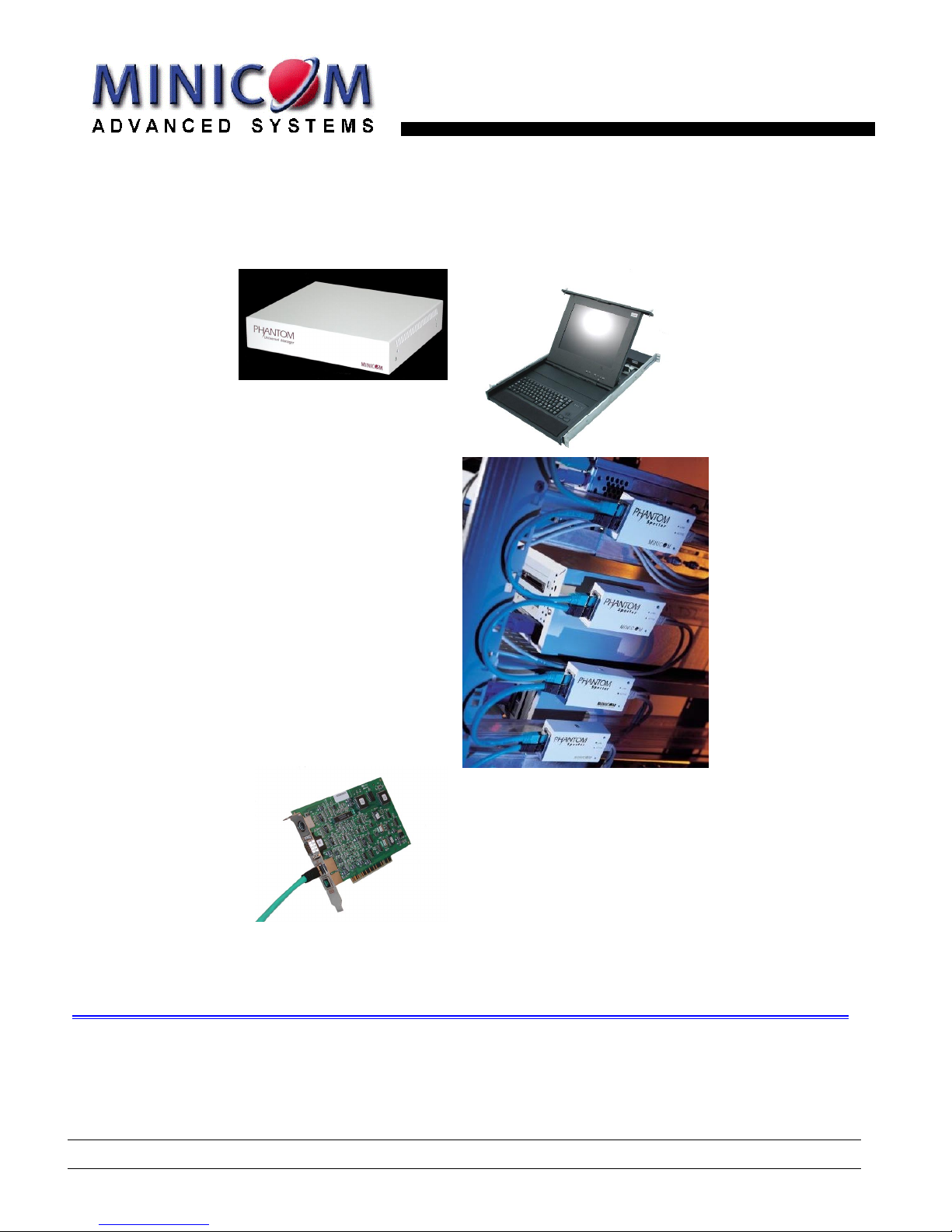
The Management unit can be either a Universal Phantom Manager (UPM) external box or an internal PCI card
Remote units
The Remote units may be either internal PCI cards or Micro-sized external boxes called Specters.
There are a number of Specter types as follows:
• For PS/2 interface computers – Specter PS/2 for 1-User system. Specter II PS/2 for a 2-User system
• For SUN computers – Specter SUN for 1 or 2-User systems
• For RS232 controllable devices – Specter RS232 for 1 or 2-User systems
• For computers with USB interfaces– Specter USB for 1 or 2-User systems
All Management and Remote models are fully compatible with each other.
Compatibility
The Phantom system is compatible with:
• IBM compatible, Silicon Graphics, SUN and Alpha computers
• VGA, SVGA, or XGA video standards
• All major computer and server manufacturers
• IntelliMouse™, Logitech WheelMouse, and PS/2 mice
• Microsoft DOS, Windows 3.1, 95, 98, 2000, NT4, ME, and XP. Novel, Linux, SGI, BeOS, HP UX Alpha UNIX, Open
VMS
• PS/2, SUN, RS232, USB interfaces
Page 3
The Phantom configuration
1-2
Features
The Phantom system gives you:
• Control and monitor mixed, multi-platform server environments of up to 63 remote computers from 1 or 2 Manager
position
• Advanced On Screen Display management (including multi-layer security), and BIOS level access
• The option to connect a keyboard, video and mouse to any Remote PCI card computer – referred to as a Local
Workstation
• A total distance of up to 110m/360ft between the Manager computer and the last connected Remote computer
• Pure hardware solution. No drivers. No IRQs. No interrupts
The Phantom configuration
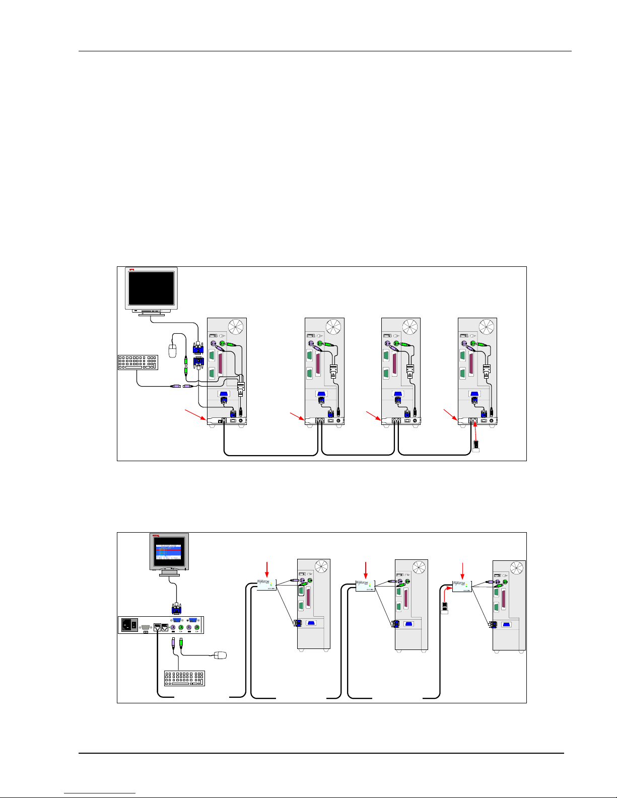
Figure 1-1 illustrates the Phantom configuration for the Manager and Remote PCI cards.
SD
P1610
Remote
Computer 1
OUT
IN
OUT
IN
OUT
IN
OUT
RS232
CAT5 System Cable CAT5 System Cable CAT5 System Cable
Terminator in the
last Phantom Unit
Manager
Computer
Remote
Computer 2
Remote
Computer 3
Manager
Card
Remote
Card
Remote
Card
Remote
Card
Figure 1-1 The card version configuration
Figure 1-2 illustrates the Phantom configuration for the UPM (without the optional computer) and Specter
models.
Link
Active
Link
Active
Link
Active
CAT5 System Cable CAT5 System Cable
Remote
Computer 1
Remote
Computer 2
Remote
Computer 3
Terminator
in the last
Phantom Unit
Specter Specter Specter
UPM
www.minicom.com
USER COMPUTER
SYSTEM SERVICEPOWER
85-265VAC 50/60 Hz
CAT5 System Cable
SD
P50
Figure 1-2 The Phantom Specter configuration with the UPM
Page 4
Introduction
1-3
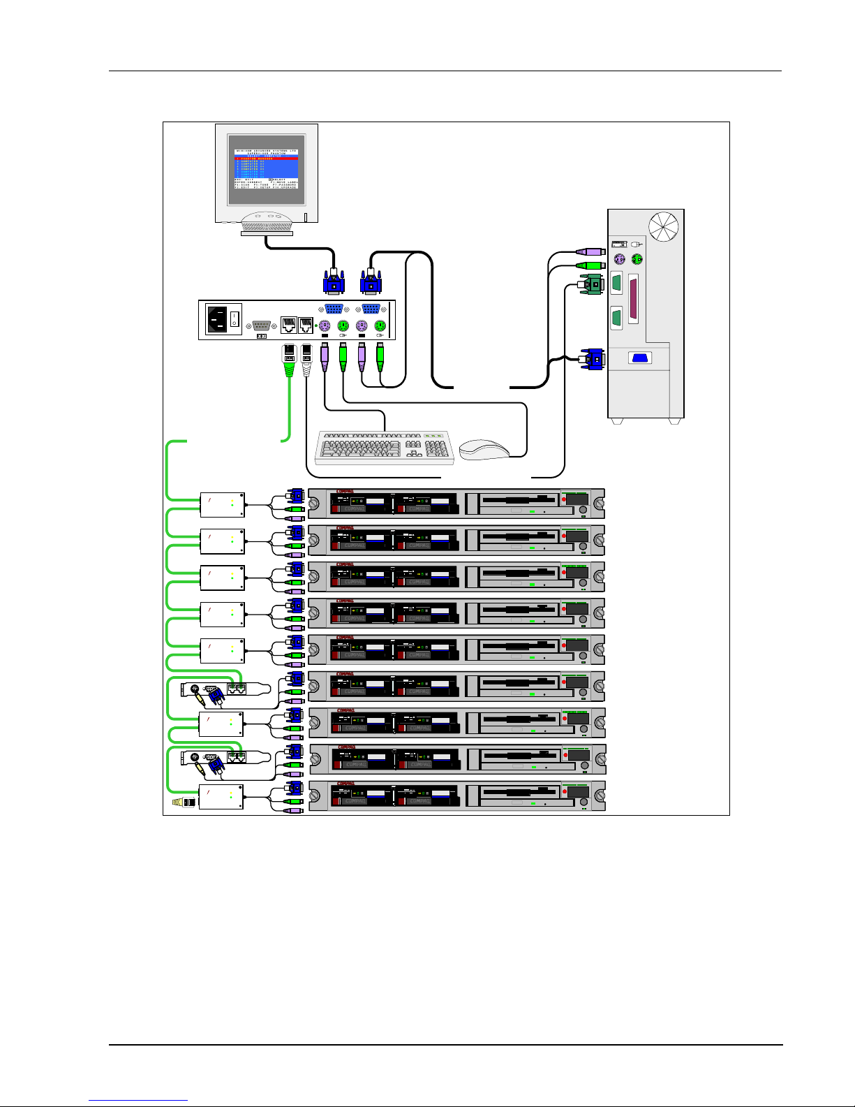
The configuration diagram below shows both Remote PCI cards and Specters in the Phantom UPM system.
CAT5 System Cable
ProLiant DL360
9.1 - GB
10k
ULTRA2 SCSI
9.1 - GB
10k
ULTRA2 SCSI
ProLiant DL360
9.1 - GB
10k
ULTRA2 SCSI
9.1 - GB
10k
ULTRA2 SCSI
ProLiant DL360
9.1 - GB
10k
ULTRA2 SCSI
9.1 - GB
10k
ULTRA2 SCSI
ProLiant DL360
9.1 - GB
10k
ULTRA2 SCSI
9.1 - GB
10k
ULTRA2 SCSI
ProLiant DL360
9.1 - GB
10k
ULTRA2 SCSI
9.1 - GB
10k
ULTRA2 SCSI
ProLiant DL360
9.1 - GB
10k
ULTRA2 SCSI
9.1 - GB
10k
ULTRA2 SCSI
www.minicom.com
USER COMPUTER
SYSTEM SE RVICEPOWER
85-265VAC 50/60 Hz
Link
Active
MINICOM
www.minicom.com
PHANTOM
Specter
OUT IN
Link
Active
MINICOM
www.minicom.com
PHANTOM
Specter
OUT IN
Link
Active
MINICOM
www.minicom.com
PHANTOM
Specter
OUT IN
Link
Active
MINICOM
www.minicom.com
PHANTOM
Specter
OUT IN
Link
Active
MINICOM
www.minicom.com
PHANTOM
Specter
OUT IN
3 in 1 Cable
SD
P110
RS232 Serial Cable
Optional
ProLiant DL360
9.1 - GB
10k
ULTRA2 SCSI
9.1 - GB
10k
ULTRA2 SCSI
ProLiant DL360
9.1 - GB
10k
ULTRA2 SCSI
9.1 - GB
10k
ULTRA2 SCSI
ProLiant DL360
9.1 - GB
10k
ULTRA2 SCSI
9.1 - GB
10k
ULTRA2 SCSI
Link
Active
MINICOM
www.minicom.com
PHANTOM
Specter
OUT IN
Link
Active
MINICOM
www.minicom.com
PHANTOM
Specter
OUT IN
OUT
IN
OUT
IN
UPM
Figure 1-3 Phantom mixed configuration with the UPM
Page 5
The Phantom configuration
1-4
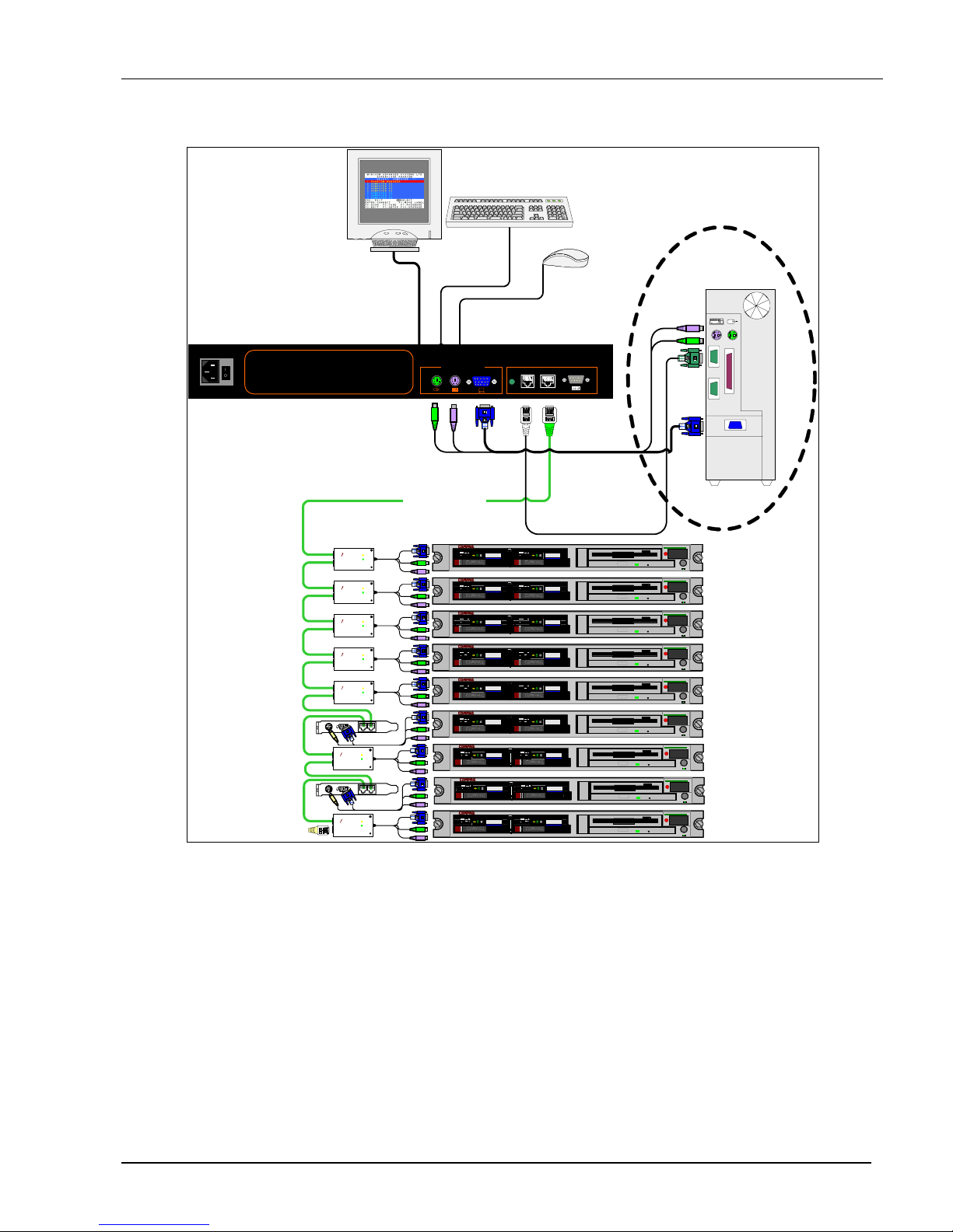
The configuration diagram below shows both Remote PCI cards and Specters in the Phantom RackManager
UPM system.
CAT5 System cable
ProLiant DL360
9.1 - GB
10k
ULTRA2 SCSI
9.1 - GB
10k
ULTRA2 SCSI
ProLiant DL360
9.1 - GB
10k
ULTRA2 SCSI
9.1 - GB
10k
ULTRA2 SCSI
ProLiant DL360
9.1 - GB
10k
ULTRA2 SCSI
9.1 - GB
10k
ULTRA2 SCSI
ProLiant DL360
9.1 - GB
10k
ULTRA2 SCSI
9.1 - GB
10k
ULTRA2 SCSI
ProLiant DL360
9.1 - GB
10k
ULTRA2 SCSI
9.1 - GB
10k
ULTRA2 SCSI
ProLiant DL360
9.1 - GB
10k
ULTRA2 SCSI
9.1 - GB
10k
ULTRA2 SCSI
Link
Active
MINICOM
www.minicom .com
PHANTOM
Specter
Link
Active
MINICOM
www.minicom .com
PHANTOM
Specter
Link
Active
MINICOM
www.minicom .com
PHANTOM
Specter
Link
Active
MINICOM
www.minicom .com
PHANTOM
Specter
Link
Active
MINICOM
www.minicom .com
PHANTOM
Specter
SD
P110
Optional
ProLiant DL360
9.1 - GB
10k
ULTRA2 SCSI
9.1 - GB
10k
ULTRA2 SCSI
ProLiant DL360
9.1 - GB
10k
ULTRA2 SCSI
9.1 - GB
10k
ULTRA2 SCSI
ProLiant DL360
9.1 - GB
10k
ULTRA2 SCSI
9.1 - GB
10k
ULTRA2 SCSI
Link
Active
MINICOM
www.minicom.com
PHANTOM
Specter
Link
Active
MINICOM
www.minicom.com
PHANTOM
Specter
OUT
IN
OUT
IN
85-265VAC50/60 Hz
Phantom
Universal Manager
www.minicom.com
MINICOM
SERVICE SYSTEM
COMPUTER
RackManager
Front panel
3in1CPUcable
RS232 Serial cable
Figure 1-4 Phantom mixed configuration with the RackManager UPM
Page 6

OSD Technology
1-5
OSD Technology
The Phantom system superimposes a menu on the Manager position computer screen. This On-Screen-Display
(OSD) consists of three sections. From the OSD, you activate various functions discussed in the Operating guide.
The Local Workstation Option
When using the Phantom Remote PCI cards, you have the option of working at the remote computer by
connecting a keyboard, video, and mouse to it. This is called the Local Workstation option.
The Phantom Manager and the local user can both work on the remote computer with a one second AccessTimeout. This means that when one of them stops working for one second the other can take control.
Note! This option is not available with the Phantom Specter.
Page 7
The OSD functions
2-1
Chapter 2: The OSD functions
The Phantom system is controlled and monitored through an On-Screen-Display (OSD) on the Manager screen.
When the Phantom Manager is the UPM you can also use Minicom’s Control software or equivalent software.
The Control software is discussed in chapter 4. The OSD contains a number of different windows that are
accessed using Hot-keys. Each window has its own special function.
Displaying the OSD
To display the OSD:
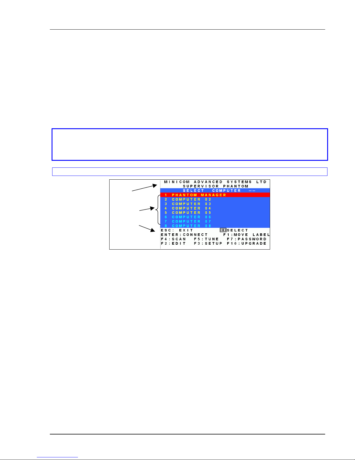
Press Shift, Shift. The Select Computer window appears. See Figure 2-1.
Pressing keyboard hotkeys
Note! For all keyboard hotkey sequences mentioned in this guide – press the first key, release and then
press the next key.
Note! When using a UPM not connected to a local computer the OSD appears automatically.
Instructions
and
Hot-keys
Computers
Name
Figure 2-1 The Select Computer window
The OSD is divided into three sections. These are:
• Name
• Computers
• Instructions and Hot-key guide
The Computers section
The Computers section displays the computers in groups of eight.
Navigate between the groups with the Page Up and Page Down Arrow keys.
In this section you select computers - discussed below.
Line Color codes
Each computer line can be one of three colors as follows:
Yellow Connected and switched on computer.
Black Connected and switched on computer with a Local Workstation attached and presently being
used locally. After remaining idle for 30 seconds, it changes to yellow.
Blue Unconnected or switched off computer.
Page 8

The hotkey functions
2-2
Selecting a Computer
To select a computer:
1. Navigate to the desired computer with the Up and Down Arrow keys.
Or
Type the computer number. It will appear in the “SELECT COMPUTER” line. See Figure 2-1.
2. Press Enter. The selected computer’s screen replaces the Manager’s screen. A Confirmation label appears
showing which computer is accessed. See Figure 2-2. Control and monitor the computer from the Manager
KVM position.
Figure 2-2 The Confirmation label
To return to the OSD:
Press Shift, Shift.
To return to the Manager computer screen:
Press Shift, Esc.
To return to the previously accessed computer screen:
Press Shift, Tab.
The hotkey functions
The OSD hotkey functions are briefly outlined in the table below.
Hotkey Function
F1 Move label identifying the current selected computer to anywhere on the screen
F2 Opens Edit window to edit text – change computer names etc.
F3 Opens Setup window to set parameters – scan times etc.
F4 Activate scan
F5 Image tuning
F6 Autoskip – during a scan skip inactive computers
F7 Opens Password window to activate password protection – explained in chapter 3
F8 Keyboard language
F9 Change the display hotkey
F10 Firmware upgrade/ Numbering software access mode – explained in chapters 5&6
F11 Load defaults – explained in chapter 4
F12 Auto-numbering – explained in chapter 3
Page 9
The OSD functions
2-3
Move Label - F1
Position the Confirmation label – Figure 2-2 above – anywhere on the screen.
To position the label:
1. Navigate to the desired computer using the Up and Down arrow keys.
2. Press F1. The selected screen image and Identification label will appear.
3. Use the arrow keys to move the label to the desired position.
4. Press Esc to save and exit.
Edit Mode window - F2
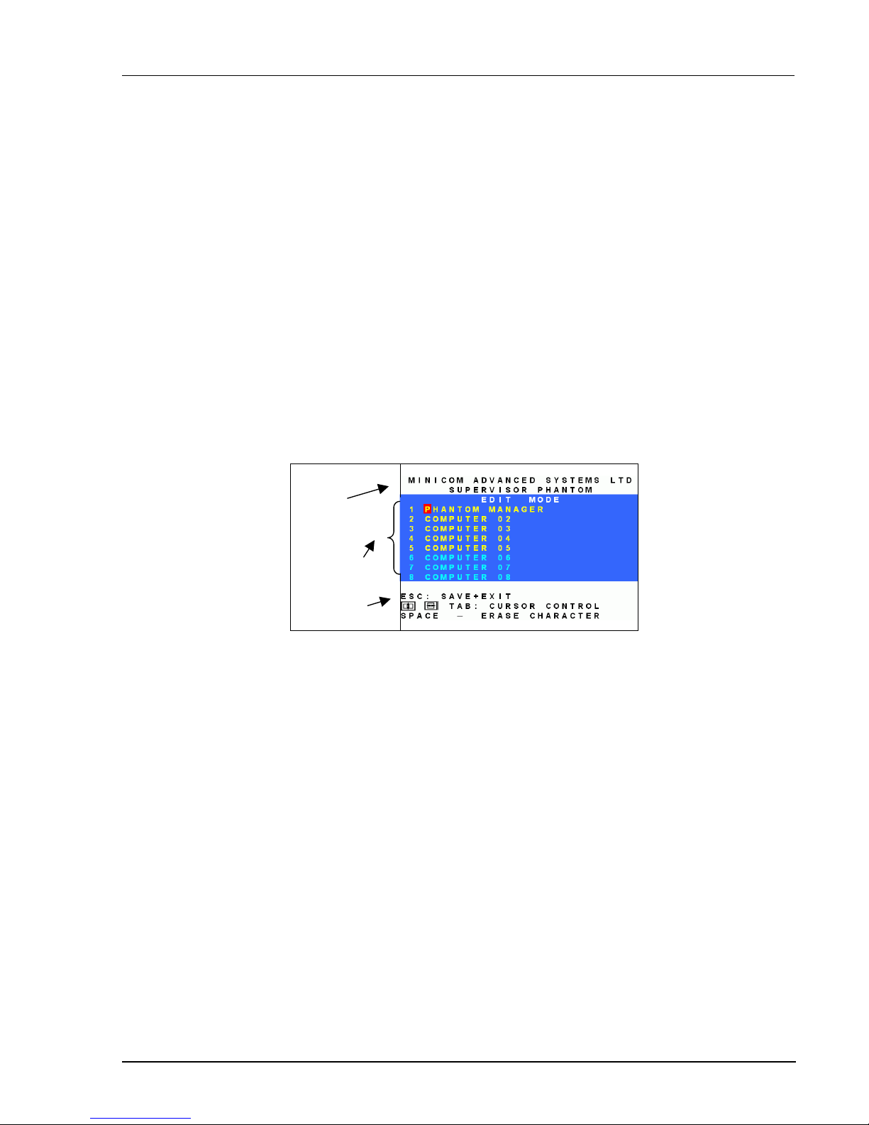
You can edit text in the Name and Computers sections. This is done in the Edit Mode window.
To display the Edit Mode window:
Press F2. The Edit Mode window with instructions appears, see Figure 2-3.
Instructions
Computers
Name
Figure 2-3 The Edit Mode window
Navigating between sections
To navigate between the Name and Station sections, use the Up and Down Arrow keys.
Editing options
The editing options below apply to all OSD windows in which you can edit characters.
You can either overwrite or erase a character.
To overwrite a character:
1. Navigate to it using the Arrow keys.
2. Type the new character.
To erase a character:
1. Navigate to it using the Arrow keys.
2. Press the Spacebar. The character disappears. A blank space replaces the erased character.
To erase a sequence of characters:
Page 10
The hotkey functions
2-4
1. Navigate to the first character in the sequence.
2. Press and hold the Spacebar down until you erase the sequence.
Saving changes
To save all editing changes and return to the Select Computer window:
Press Esc.
Editing the Name section
You can substitute the text in the Name section with up to 30 characters in each of the two lines. A space
constitutes a character.
Editing the Computers section
The numbering at the start of each line is unalterable.
You can substitute the text that appears after the number with up to 20 characters per line.
Editing a group of lines
You can edit a group of lines with the same data change.
To edit a group of lines:
1. Navigate to the first line you want to change.
2. Type the desired change.
3. Press End, End. The rest of the column downwards takes on the same change.
The Setup window - F3
You set parameters, and configure settings, in the Setup window.
To display the Setup window:
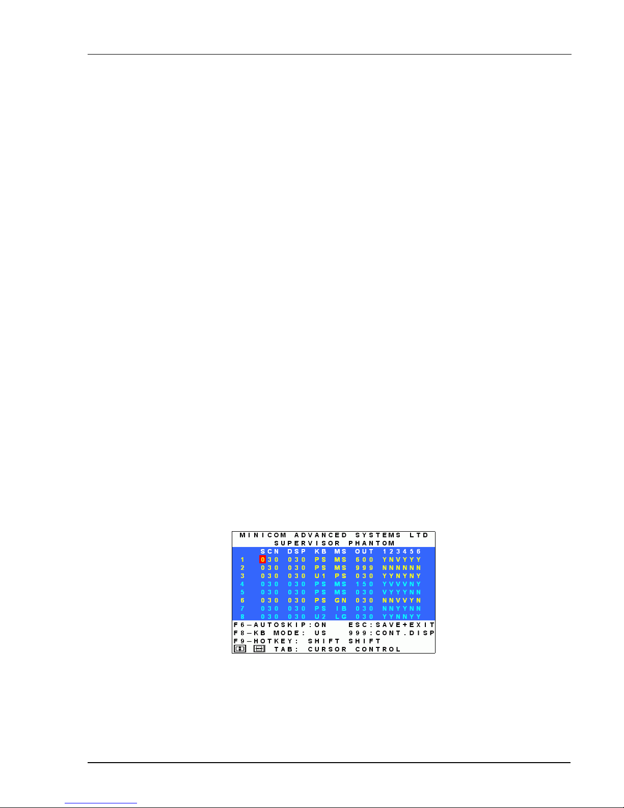
Press F3. The Setup window with the relevant instructions and hotkeys appears. See Figure 2-4.
Figure 2-4 The Setup window
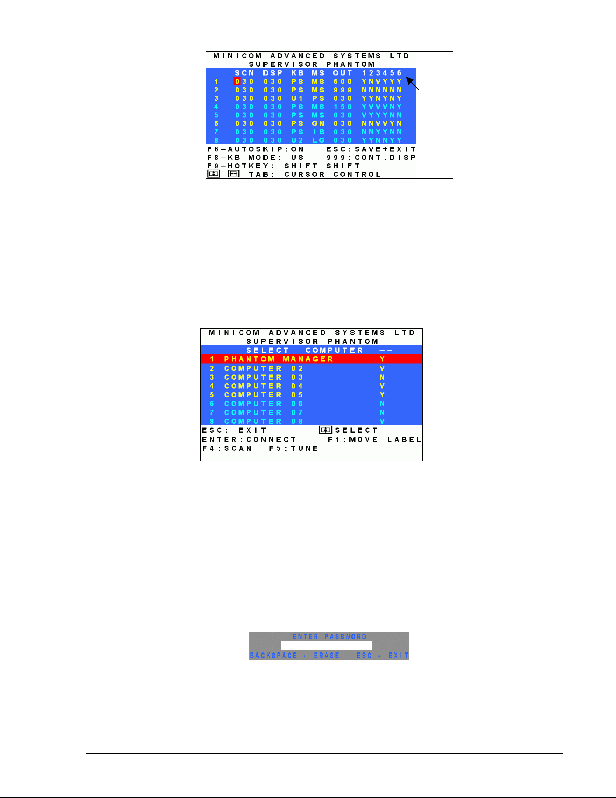
The Setup window contains 7 columns, as follows:
Page 11

The OSD functions
2-5
Column Function
Numbers Computer numbers in groups of 8
SCN Scanning time period
DSP Confirmation label display time
KB Keyboard setting, either PS or Unix
MS Mouse type
OUT Security Timeout period (Explained in chapter 3)
1-6 Security profiles (Explained in chapter 3)
The SCN (Scan) column
The SCN column shows the length of time in seconds that a remote computer’s screen will appear on the
Management screen during scanning.
The DSP (Display) column
The DSP column shows the length of time in seconds that the remote computer’s Confirmation label appears
on the Management screen.
Changing the SCN and DSP time spans
The SCN and DSP time spans are preset to 030 seconds. You can adjust these times to suit your needs.
To change the time span:
1. Navigate with the Tab or Right and Left Arrow keys to the time span you want to change.
2. Type the desired time span using the numbers above the keyboard letters.
3. Press Esc.
When typing over a group of three digits, the cursor automatically reverts to the first digit once you edit the
third digit.
Changing the time span of a group of computers
You can change the time spans of the SCN and DSP columns from a particular computer downwards.
To change the time span:
1. Navigate to the time span of the first computer you wish to change.
2. Type the desired change.
3. Press End, End. The remainder of the column takes on the same change.
4. Press Esc.
Page 12

The hotkey functions
2-6
Removing a computer from the scanning sequence
To remove a computer from the scanning sequence:
1. Type 000 in the SCN column.
2. Press Esc.
Constantly displaying the Confirmation label
To constantly display the computer Confirmation label:
1. Type 999 in the DSP column.
2. Press Esc.
The KB column
The KB column shows the keyboard mapping settings. Set the KB mapping for each computer according to its
operating system.
The default KB mode is PS, which is the standard keyboard mapping for Windows and Linux based operating
systems.
For a UNIX operating system using a standard PS/2 keyboard, set the KB mapping as follows:
• U1 for HP UNIX and SGI
• U2 for Alpha UNIX and Open VMS
To change the KB column from PS to U1 or U2:
1. Navigate to the KB field by using the Tab or Arrow keys.
2. Press the Spacebar. The display interchanges between PS, U1 and U2. Find the desired setting.
3. Press Esc.
The MS column
The Phantom system automatically detects the mouse types, and configures the system accordingly.
Page 13

The OSD functions
2-7
Scanning Computers – F4
You scan computers from the Select Computer window.
To start scanning:
Press F4. During scanning a Confirmation label appears, showing which Remote computer is presently
displayed. See Figure
2-5.
Figure 2-5 The Scan Confirmation label
Note! The scan will skip any active computer set to 000 in the SCN column.
To stop scanning press F4.
Image tuning - F5
You can tune the image of any remote computer screen from the Select Computer window.
To adjust the screen image:
1. Navigate to the remote computer you wish to adjust.
2. Press F5. The screen image of the selected computer appears, together with the Image Tuning label. See
Figure
2-6.
Figure 2-6 The Image Tuning label
3. Adjust the image by using the Right and Left Arrow keys.
4. When the image is satisfactory, press Esc.
Note! Picture quality is relative to distance. The further away a remote computer is from the Manager position,
the lower the image quality, and the more tuning needed. So place the higher resolution computers closer to the
manager unit.
Page 14

The OSD functions
Skipping out unconnected or switched off computers- F6
When navigating through the list of computers, you can skip out the unconnected or switched off computers.
You do this with Autoskip. By default, Autoskip is activated.
To activate or deactivate Autoskip:
In the Setup window (F3), press F6. The F6 Autoskip in the hotkey section of the OSD changes from ON to
OFF
When Autoskip is inactive and the computer being scanned is switched off, then the Manager screen appears
dark.
Changing the keyboard language - F8
You can change the keyboard language from US English (QWERTY) US to German (QWERTZ) DE or
French (AZERTI) FR.
To change the Language:
1. In the Setup window (F3), press F8 unt il you reach the desired language.
2. Press Esc.
Changing the OSD display hotkey – F9
The default hotkey to display the OSD, is Shift, Shift. You can replace this hotkey with any of the following:
For the Manager PCI card:
•
Ctrl, Ctrl
•
Ctrl, F11
•
Ctrl, F12
With a choice of 4 different hotkeys, you can operate up to 4 OSDs from 1 KVM position. Each OSD needs a
different display hotkey. This is useful for cascading systems of for example, the Supervisor MU, Supervisor
Pro, and Phantom.
To change the hotkey:
1. In the Setup window (F3), press F9 . The hotkey changes from Shift, Shift to Ctrl, Ctrl. Continue pressing
until you reach the required hotkey.
2. Press Esc. The new hotkey is set. From now on, use the new hotkey to display the OSD.
For the UPM:
•
Ctrl, Ctrl
•
Ctrl, F11
•
Print Screen
Exiting the OSD
When the OSD is displayed press Esc to exit the OSD and remain switched to the current computer.
2-8
Page 15

Password protecting the OSD & Auto numbering
3-1
Chapter 3: Password protecting the OSD & Auto
numbering
The Management OSD comes with an advanced password security system that contains 3 different security
levels. Each security level has different access rights to the system.
These levels are as follows:
Administrator (Status A) - Highest
The Administrator can:
• Set and modify all Passwords and security profiles
• Fully access any computer
• Use all OSD functions
Supervisor (Status S) - Middle
The Supervisor can:
• Fully access any computer
• Access the following OSD functions only – F1 Moving the Confirmation label. F4 Scan and F5 Tune.
User (Status U) – Lowest
There are 6 different Users in the Phantom system. Each User has a Profile that defines the access level to
different computers. There are 3 different access levels. These are:
• Y – Full access to a particular computer
• V –Viewing access only, to a particular computer (No keyboard/mouse functionality)
• N – No access to a particular computer – A TIMEOUT label appears if access is attempted
The Administrator defines the desired access levels of each User Profile. This is done in the OSD Setup
window. By default the User Profile settings are full access.
NOTE: There can only be 1 Administrator password, 1 Supervisor password, and 6 User passwords.
Page 16
Enabling password protection
3-2
Enabling password protection
By default, password protection is disabled.
To enable password protection:
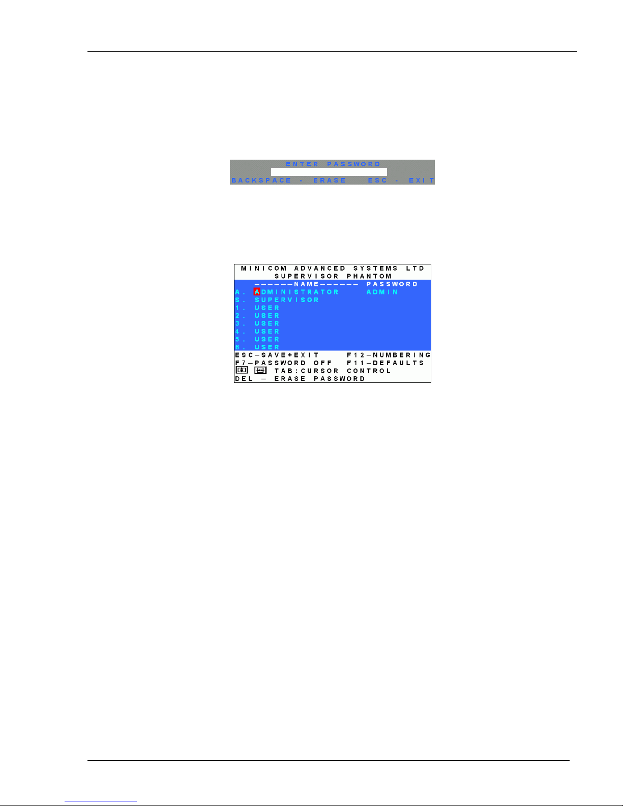
1. From the Management OSD Select Computer window press F7. The Password box appears. See Figure
3-1.
Figure 3-1 The Enter Password box
2. Type the default password “admin”. (You can change this password when customizing the security
system).
3. Press Enter. The Password window appears. See Figure 3-2.
Figure 3-2 The Password window
4. Press F7. The Confirmation label appears. The password indication in the hotkey section of the OSD
changes to PASSWORD ON.
5. Press ‘Y’ to confirm. Password protection is now enabled.
6. Press Esc.
Disabling password protection
To disable the password protection:
1. Enter the OSD Select Computer window with the Administrator’s password.
2. Press F7. The Password window appears.
3. Press F7 again to disable Password protection. The Confirmation label appears. The password indication
in the hotkey section of the OSD changes to PASSWORD OFF.
4. Press ‘Y’ to confirm. Password protection is now disabled.
5. Press Esc.
Page 17
Password protecting the OSD & Auto numbering
3-3
Setting up a password
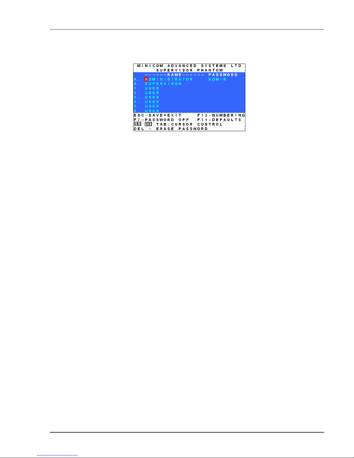
The Administrator sets up passwords for each User Profile in the Password window. See Figure 3-3. He can
also edit the names to give each Profile a more identifiable name.
Figure 3-3 The Password window
To set up a password:
1. From the OSD Select Computer window press F7. The Enter Password box appears.
2. Type the Administrator’s password.
3. Press Enter. The Password window appears. See Figure 3-3. The first row marked A is for the
Administrator name and password and the second row marked S is for the Supervisor name and password.
Note! Password characters are not case sensitive, and a space can be a password character. A space will appear
as an asterix.
To set up a password:
1. Navigate to the desired line number.
2. Type:
(i). Identifiable name in the Name column.
(ii). Password in the Password column – between 1 and 8 characters.
3. Press Esc.
Changing a password
The Administrator can change any name or password from the Password window.
To change a name or password:
1. Navigate to the desired line number.
2. Delete the text by pressing Delete.
3. Type the desired change.
4. Press Esc.
Setting the User profiles access level
Set the 6 User profiles access levels from the OSD Setup window (F3). See Figure 3-4. The 6 User Profiles
correspond to the 6 Users in the Password window see Figure 3-3 above.
Page 18
Accessing the OSD using a password
3-4
The 6
User
Profiles
Figure 3-4 The Setup window
To set the User Profiles access levels:
1. Navigate to the desired User Profile and computer.
2. Change the desired access level by pressing the Spacebar.
3. Repeat steps 1 and 2 for each User Profile and computer.
4. Press Esc to save the changes. When a User accesses the system with their password they see the access
levels for each computer displayed on the OSD. See Figure 3-5.
Figure 3-5 User access levels
Accessing the OSD using a password
Once password protection is enabled, you can only access the OSD by entering the appropriate password.
The default Administrator’s password is “ADMIN”. The passwords of the other two security statuses are set by
the Administrator.
To access the OSD:
1. Press Shift, Shift. The Enter Password box appears. See Figure 3-6.
Figure 3-6 The Enter Password box
2. Type in the appropriate password.
3. Press Enter.
Page 19

Password protecting the OSD & Auto numbering
3-5
Timeout
When password protection is activated you can automatically disable the Management keyboard, mouse and
screen after a preset time of non-use. You set the Timeout period in the OUT column of the Setup window
(F3).
By default the OUT column is set to 999, which means that the Time Out function is disabled.
To set Timeout:
1. From the Select Computer window press F3. The Setup window appears.
2. Navigate with the Tab or Arrow keys to the OUT column of the desired computer.
3. Type the desired time span (minimum 030 seconds maximum 998 seconds).
( For the rest of the column downwards to take on the same change press End, End.)
4. Press Esc.
When Timeout is activates the keyboard and mouse are disabled and the monitor blacks out with a ‘Timeout’
label.
Figure 3-7 The TIMEOUT label
To re-enter the system:
Press Shift, Shift.
Type the password and press Enter. You re-enter the system.
Reverting to the default OSD settings - F11
The Administrator can reset all editing and configurations done in the different OSD windows, to the default
factory settings.
Warning! This feature will erase all settings including computer names, passwords and security profiles.
To revert to the default OSD settings:
1. Enter the Password window (F7).
2. Press F11.
3. Press ‘Y’ to confirm. The OSD reverts to the default settings.
Page 20
Auto numbering – F12
3-6
Auto numbering – F12
Auto numbering gives each Phantom Remote a sequential ID number. Auto numbering is done through the
Management OSD.
For Auto numbering to work properly ALL connected computers MUST be switched on
To perform Auto numbering:
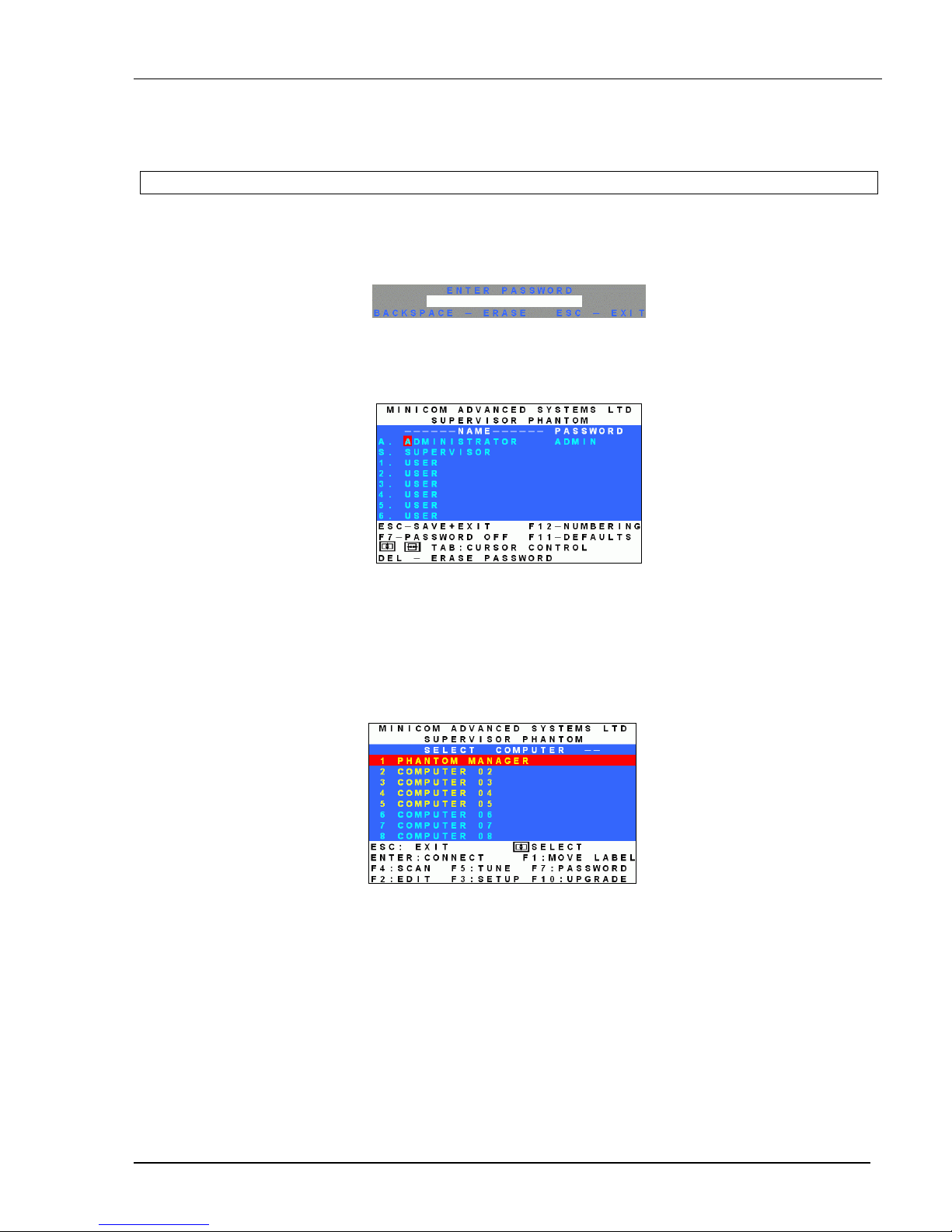
1. From the OSD Select computer window Press F7. The Enter Password box appears. See Figure
3-8.
Figure 3-8 The Enter Password box
2. Type the Administrators password (default password is ADMIN) and press Enter. The Password
window appears.
Figure 3-9 The Password window
3. Press F12 to activate Auto numbering. A Confirmation label appears.
4. Press Y to confirm. The process activates. Wait until the process is complete.
5. Press Esc to save and return to the Select Computer window. The Remote computers appear on the OSD.
See Figure
3-10.
Figure 3-10
Page 21

Operating the Phantom system with the Control software
4-1
Chapter 4: Operating the Phantom system with
the Control software
As an alternative to the OSD you can operate the Phantom system with the Control software located on the
Marketing & Documentation CD. With the OSD you operate the system and view the computer screens on the
same monitor. The Control software requires 2 monitors 1 for the software and 1 to view the computer screens.
With the Control software you can:
• View computers
• Edit server properties
• Save configurations for future use
• Read configurations from and write configurations to the Phantom Manager
Control software system requirements
• Pentium 166 or higher computer
• 16Mb RAM
• Windows 98, NT4 (SP6), 2000, ME or XP
• Free Serial port
Connecting the RS232 Serial cable
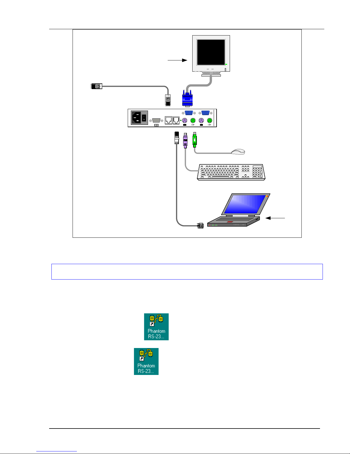
To run the software, connect the RS232 Serial cable to the computer containing the software, and to the
Phantom Manager. See the figure below.
Page 22
The View menu
4-2
SD
P110
www.minicom. com
USER COMPUTER
SYSTEM SERVICEPOWER
85-265VAC 50/60 Hz
To
System
Out port
To Phantom Remote
System In port
Shielded CAT5
FTP cable
To computer’s Serial port
Computer screens
appear here
Control software
installed here
To Service
connector
RS232 Serial
cable
Figure 4-1 The UPM with the RS232 Serial cable
Installing and running the Control software
Note! The Phantom system must be fully connected BEFORE running the Control software. Failure to first
connect the system will lead to the software working in demo mode.
Start the Marketing & Documentation CD and choose Phantom Utilities Softpack. The Phantom Softpack
window appears.
To install the software choose Install Phantom RS232 Control Software. Once the software is installed, a
shortcut icon appears on the Desktop
.
To run the software double-click
Or choose Start / Programs / Phantom RS232 Control / Phantom RS232 Control.
Page 23
Operating the Phantom system with the Control software
4-3
Selecting a Com port
During the Setup process you will be prompted to choose a Com port. Choose the Com port to which the
RS232 Serial cable is connected. Failure to select the correct Com port will result in the software running in
demo mode.
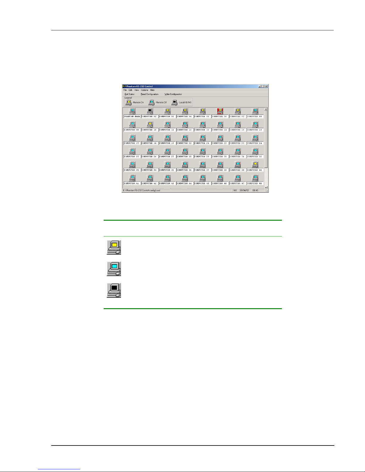
Once Setup is complete the Control window appears. See the figure below.
Figure 4-2 The Control window
Computer icons
Icon Meaning
Remote computer is connected and switched on
Remote computer is switched off or unconnected
Connected and switched on computer with a Local
Workstation attached and presently being used locally.
After remaining idle for 30 seconds, it changes to yellow.
When you first open the Control window the software automatically gets the status of the Phantom system,
including the security access settings.
Page 24
The View menu
4-4
Communication Error
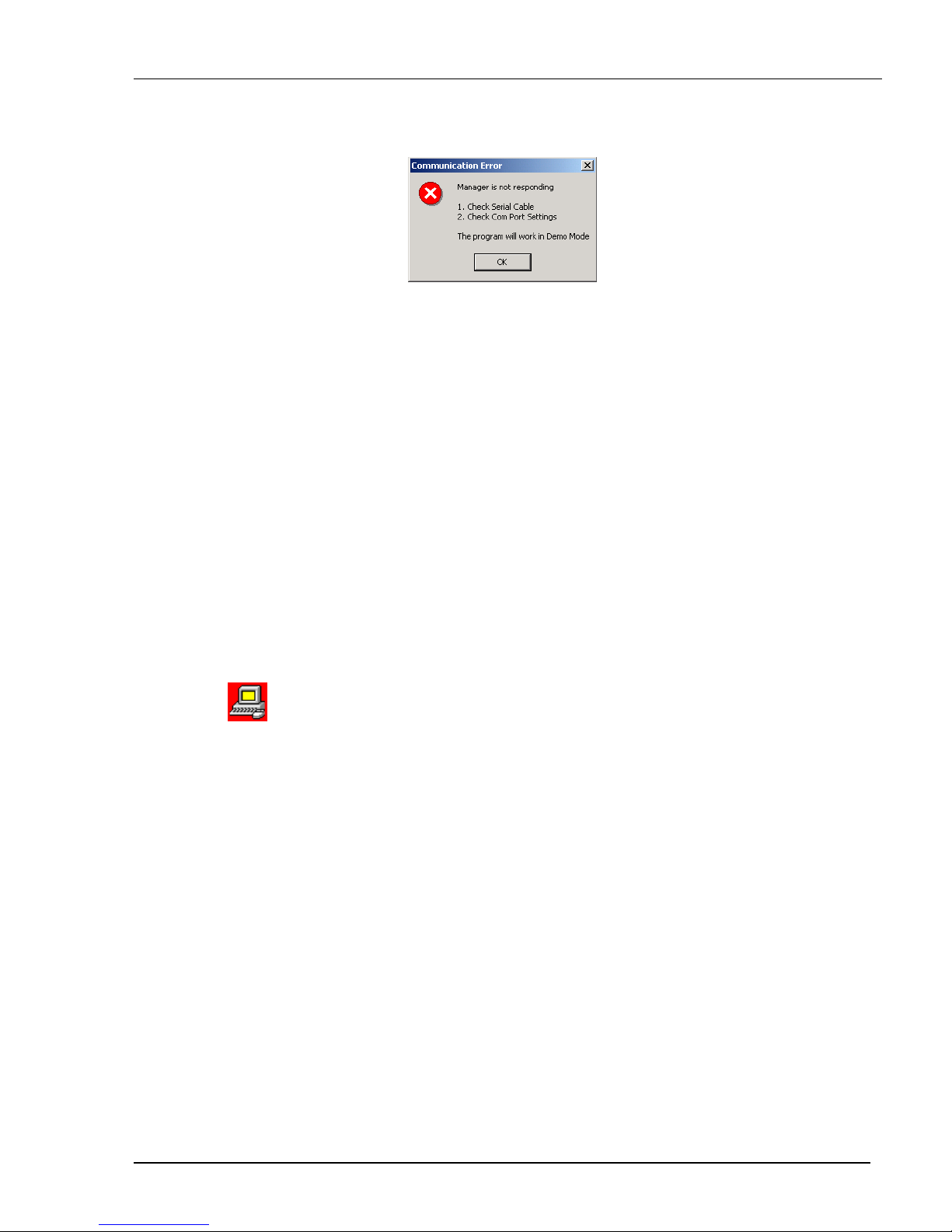
If a Communication Error box appears when trying to scan the system – see Figure 4-3.
Figure 4-3 Communication Error
Check that:
• The RS232 Serial cable is connected to the computer’s and Phantom Manager’s serial ports.
• The Com Port settings in Options / Com Port are set correctly. After changing the Com port exit and re-enter
the Control software.
The View menu
From the View menu choose to display:
• All computers, or only active switched on computers.
• The Legend
• The toolbar
Selecting a computer
To select a computer:
Click on the computers icon. The system switches to that computer. The connected icon appears with a red
background
. Control and monitor the selected computer from the keyboard and mouse connected to the
Phantom Manager.
Page 25

Operating the Phantom system with the Control software
4-5
The toolbar buttons
Get Status
If for whatever reason there is a break in communication between the Control software and the Phantom
system, click
to get the current status of the computers in system. The system automatically
updates the status before every switching.
Read Configuration
To see the current settings of the entire Phantom system (names, scan settings etc.) click .
All current settings are received. You view the computer settings from the Control window and other settings
from the Edit menu – discussed below.
Write Configuration
With the Control software you can make changes to all OSD settings. You can then save these configurations
in a file to use in the future by selecting Save or Save As from the File menu.
Note! Save or Save As will have no affect on the OSD.
To change the OSD settings you must press or choose Write Configuration from the File
menu after making changes. The changes will then be sent to the Phantom Manager, and the OSD will reflect
these changes.
Renaming a computer
To rename a computer:
1. Type the new name in the box below the computer icon.
2. Click
to send the new name to the Phantom system.
Or
Click Save or Save As from the File menu to save the change in a file and not alter the OSD names.
The Edit menu
You can edit all OSD fields.
Edit the following from the Edit menu.
• Logo
• Passwords
• Settings
Page 26
The toolbar buttons
4-6
Logo and Passwords
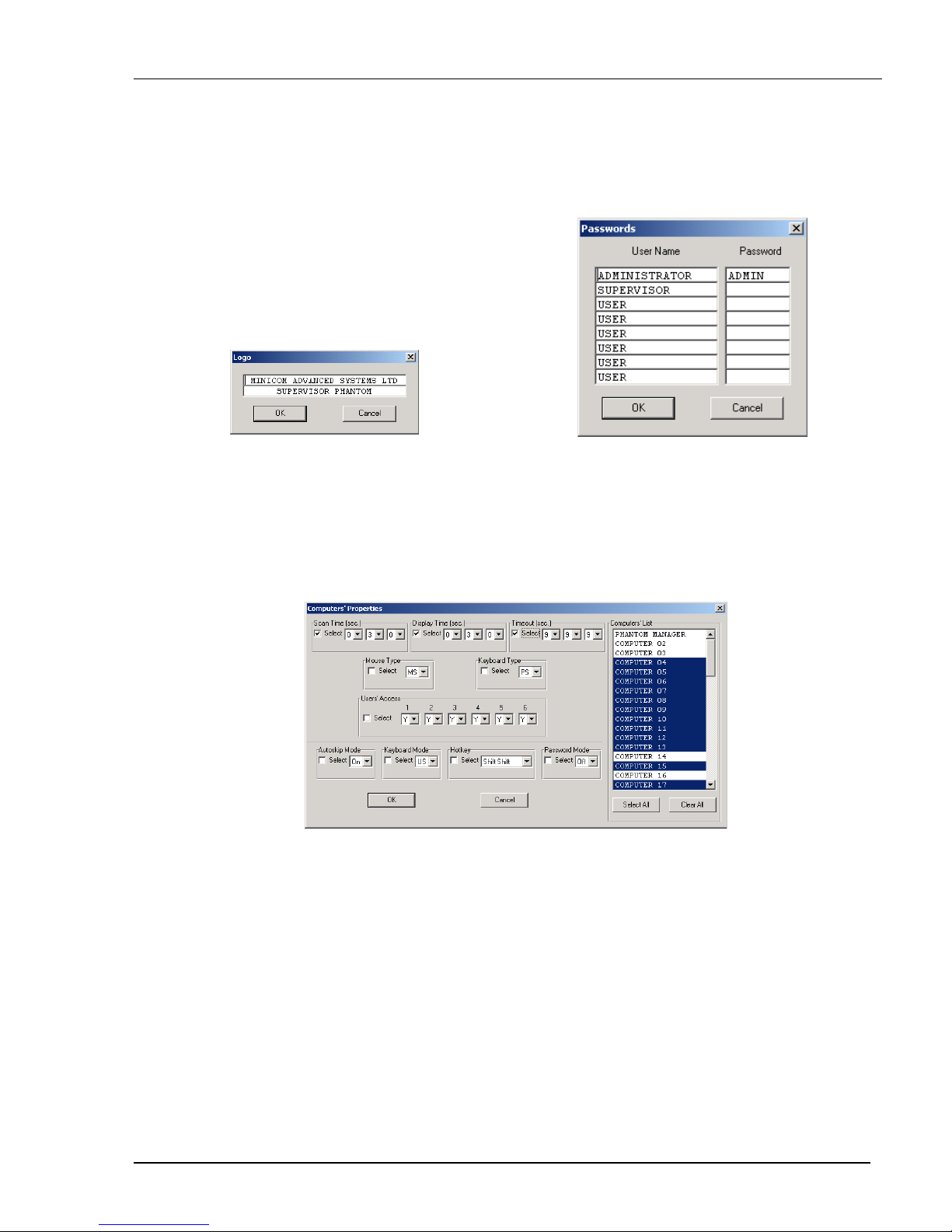
You can edit the logo that appears at the top of the OSD window. You can also edit the names and passwords
for the Administrator, Supervisor and 6 Users.
1. Edit the Logo and Passwords by choosing them from the Edit menu. See figures below.
Figure 4-4 The logo
Figure 4-5 The names and passwords
2. Make the desired changes.
3. Click OK.
Settings
Choose Settings from the Edit menu. The Computers’ Properties box appears. See Figure 4-6.
Figure 4-6 The Settings box
Here you can edit all the data that can be edited in the OSD. This includes:
Scan times, Confirmation label display time, Timeout, mouse type, keyboard type, User access, password
mode, Autoskip mode, keyboard mode – Display hotkey.
To edit a setting:
1. Select the desired computer or group of computers.
2. Make the desired changes.
3. Check the Select box next to the changed setting.
4. Click OK.
Page 27
Operating the Phantom system with the Control software
4-7
Single computer settings
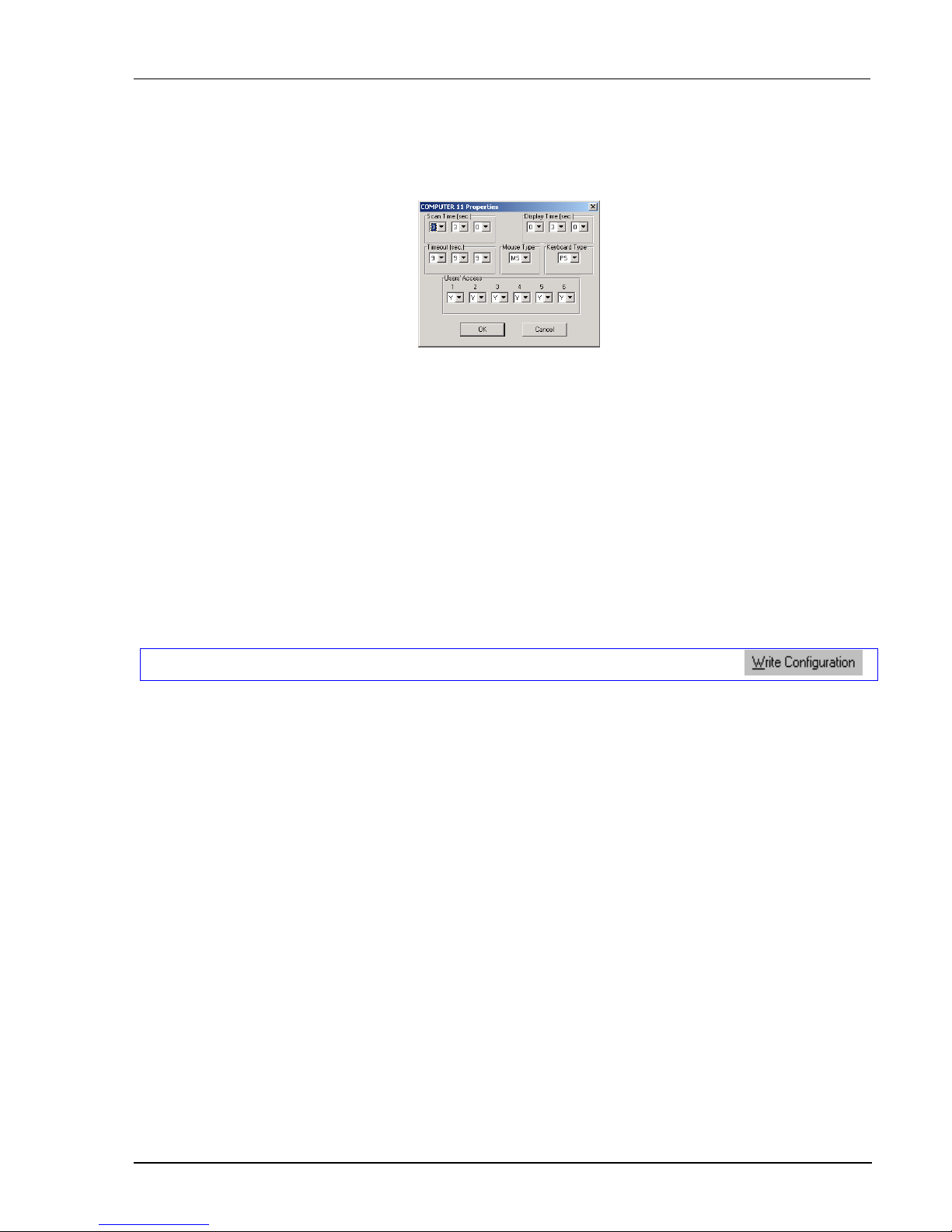
To see all the settings of a single computer right click on the computer icon. The settings appear as in the
figure below.
Note! There is no Select box to check.
Figure 4-7 The single computer Settings box
Loading a saved configuration
To load a saved configuration:
From the File menu choose Open.
The factory default settings
To view to the factory default settings:
From the File menu choose New.
Reminder!
All changes done with the Control software are only reflected in the OSD AFTER pressing .
Password protection
When the Phantom system is password protected, the Control software behaves in exactly the same way as the
OSD. You must type in the required password to access the Control software. The access you gain depends on
the security status – exactly as with the OSD.
To change the security access, close and reopen the Control software, and type in the different password.
Administrator (Status A) - Highest
The Administrator can:
• Set and modify all Passwords and security profiles
• Fully access any remote computer
• Use all functions
Supervisor (Status S) - Middle
The Supervisor can:
• Fully access any remote computer
• Scan computers.
Page 28

Password protection
4-8
User (Status U) – Lowest
There are 6 different Users in the Phantom system. Each User has a Profile that defines the access level to
different computers. There are 3 different access levels. These are:
• Y – Full access to a particular computer
• V –Viewing access only, to a particular computer (No keyboard/mouse functionality)
• N – No access to a particular computer
The Administrator defines the desired access levels of each User Profile. This is done in the Setting box. By
default the User Profile settings are full access.
Page 29
Renumbering the Phantom Remotes
5-1
Chapter 5: Renumbering the Phantom Remotes
When the Phantom system was first installed, ID numbers were assigned with the auto-numbering process.
Auto numbering gives each Phantom Remote a sequential number according to its physical location in the
daisy chain. Remote units can be renumbered according to their physical location or by manually choosing the
numbers you desire.
Renumbering is done using Phantom Numbering software. The software is on the Marketing & Documentation
CD.
Connecting the Phantom System
To renumber the Remotes the Phantom system must be connected and switched on.
Connecting the RS232 Serial cable
To run the software, connect the RS232 Serial cable to the computer containing the software, and to the
Phantom Manager. See chapter 5 of the Installation guide.
RS232 Serial cable system requirements
• Pentium 166 or higher computer
• 16Mb RAM
• Windows 98, NT4 (SP6), 2000, ME or XP
• Free Serial port
Running the Phantom Numbering software
To use the Numbering software, the OSD must be in the Numbering mode.
1. Press Shift, Shift to display the OSD.
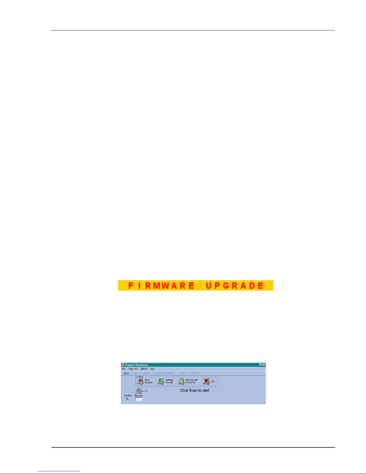
2. Press F10 to enter the Numbering mode. The Firmware Upgrade label appears. See Figure
5-1.
Figure 5-1 The Firmware Upgrade label
Start the Marketing & Documentation CD and choose Phantom Utilities Softpack. The Phantom Softpack
window appears. The Numbering Software can be installed onto the computer or operated directly from the
CD. To install the software choose Install Phantom Numbering Software.
To run the software:
Select Run Phantom Numbering Software. The Phantom Numbering window appears. See Figure
5-2.
Figure 5-2 The Phantom Numbering window
Page 30
Scanning the system
5-2
Selecting a Com port
1. From the Options menu, select Com port. The Com port no. box appears.
2. Choose the Com port to which the RS232 Serial cable is connected.
3. Click OK.
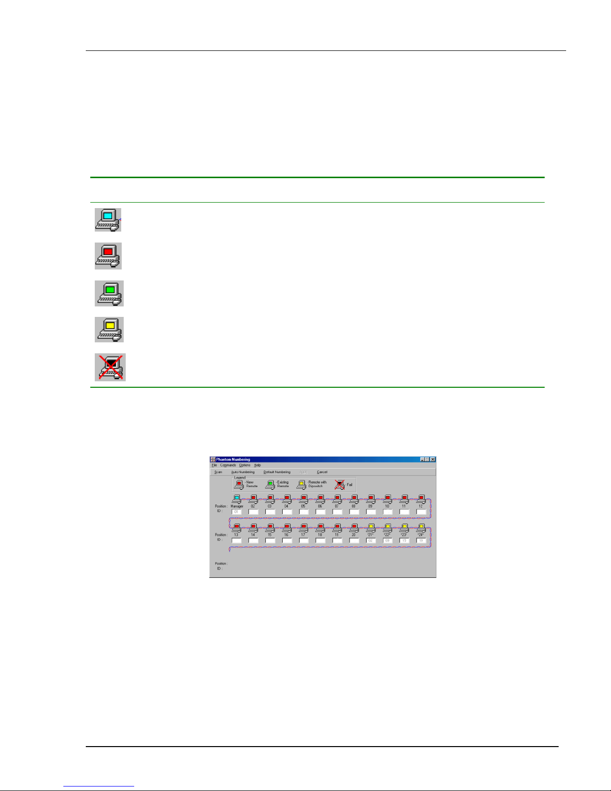
Legend
The color-coded computer icons are explained in the table below.
Icon Meaning
Manager. The ID number is fixed at 01.
New Remote. Has no ID number at present.
Existing Remote. Has an ID number.
Remote with ID number set with dipswitches. The ID number cannot be altered with the
Phantom Numbering software.
Failure to number
Scanning the system
In the toolbar, click Scan. This maps out the computers connected to the system. When finished the window
appears as in Figure 5-3.
Figure 5-3 After scanning the first time
Position and ID
The Position shows the physical location of the computer in the daisy chain. The ID is the ID number given to
each Remote. ID numbers are assigned in 1 of 3 ways - Auto numbering, Default numbering or Manual
numbering.
In Figure 5-3, the blank ID boxes indicate that no ID number has yet been assigned. The yellow icons show the
position and ID numbers of Remotes with dipswitches.
Page 31

Renumbering the Phantom Remotes
5-3
Auto numbering
Auto numbering fills in any blank ID number boxes with the first available free ID number.
To perform Auto numbering:
1. In the toolbar, click Auto Numbering. All blank boxes are filled in.
2. Click Apply. The process activates. When finished new ID numbers are assigned to the Remotes. The
icons change to green.
Default numbering
Default numbering assigns ID numbers according to the physical location of each Remote.
To perform Default numbering:
1. In the toolbar, click Default Numbering.
2. Click Apply. The process activates. When finished the ID numbers are assigned according to the
physical position of the units.
Manual numbering
Manual numbering involves selecting an ID number box and assigning a number from the Drop-down numbers
list. See Figure 5-4. Only numbers that have not been assigned are available.
Note! Numbering a Remote 00 removes it from the system.
To perform Manual numbering:
1. Select an ID number box and choose a number.
2. Click Apply. The process activates, and the ID number assigns.
Figure 5-4 The Drop-down menu
Using 00 or blank ID numbers
You may want to swap ID numbers between Remotes, or give a Remote the ID number of another Remote. To
do this, renumber a Remote to either 00 or blank. The previous ID number now becomes available to assign to
another Remote.
Page 32
Remote with dipswitches
5-4
Remote with dipswitches
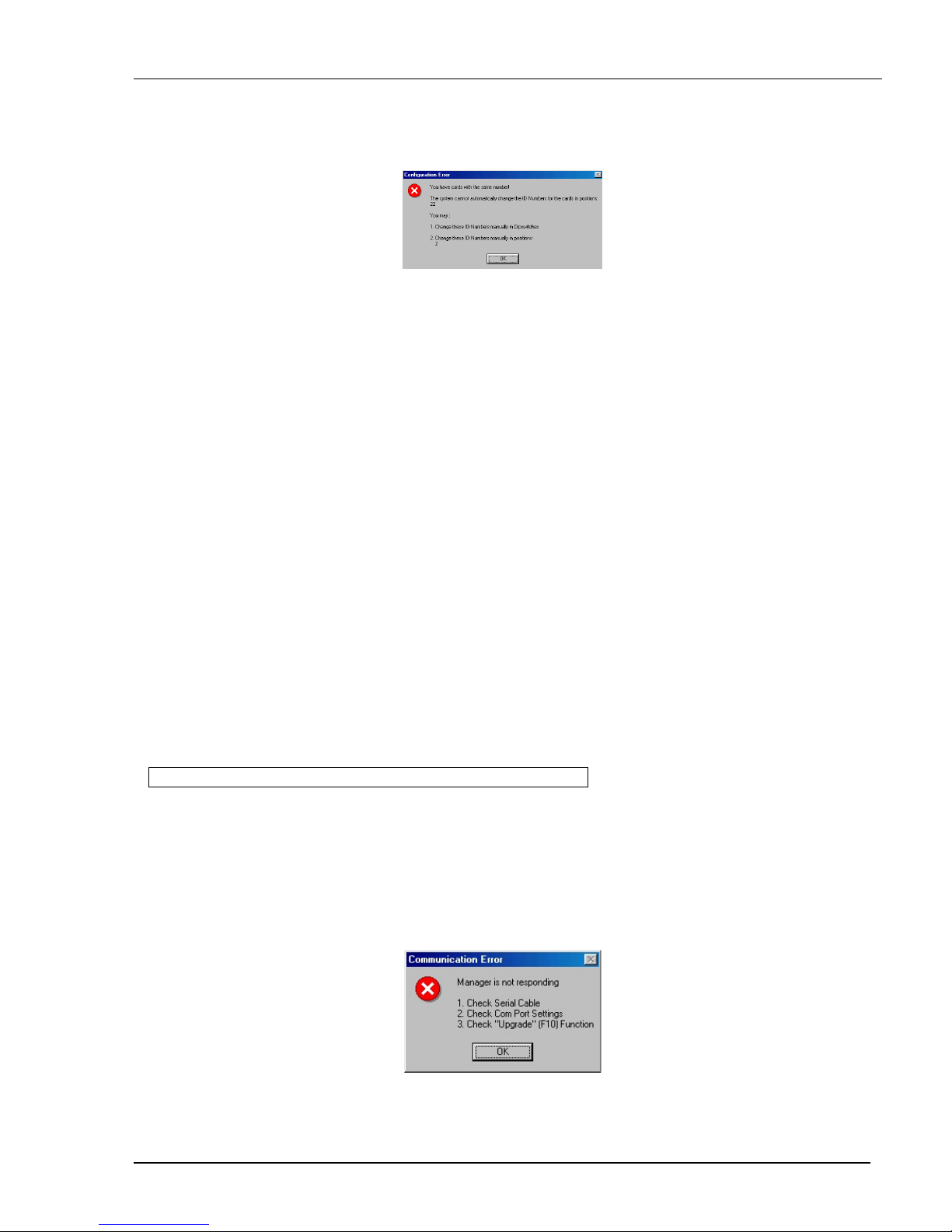
When adding a Remote with dipswitches to the system, check that it does not have an ID number that is
already in use. If it does, then when performing the scan, a Configuration Error box appears. See Figure 5-5.
Figure 5-5 Configuration error
To rectify this:
Either change the ID number of the Remote with dipswitches.
Or
Use the Phantom Numbering software to adjust the ID number of the identically numbered Remote. This can
be done with any of the three methods set out above – Auto, Default or Manual numbering.
Cancel
After making changes to ID numbers using the Auto, Default or Manual numbering, but BEFORE clicking
Apply, you can revert to the position as it was before the changes.
To do so:
Click Cancel.
Restore
After making changes to ID numbers using the Auto, Default or Manual numbering, and AFTER clicking
Apply, you can revert to the position as it was before the changes.
To do so:
From the Options menu, select Restore.
Note! Restore is only available BEFORE the new scan is activated.
Communication Error
If a Communication Error box appears when trying to scan the system – see Figure 5-6. Check the following:
• The RS232 Serial cable is connected to the computer’s and Phantom Manager’s serial ports.
• The Com Port settings in Options/Com Port are set correctly.
• The Firmware Upgrade label (F10) appears on the screen. See Figure 5-6.
Figure 5-6 Communication Error
Page 33

Renumbering the Phantom Remotes
5-5
Fail icons
When after a carrying out a numbering procedure, Fail icons appear – see Figure 5-7. Wait 30 seconds and
repeat the numbering procedure.
Figure 5-7 Fail icons
Page 34

Upgrading the Phantom firmware
6-1
Chapter 6: Upgrading the Phantom firmware
With the Phantom Update software program you can upgrade the firmware for the:
• OSD
• Manager
• Remote
Phantom Update enables you to add new features and fix bugs in a quick and efficient manner.
You can install Phantom Update on the Manager computer or any other computer, even one not part of the
Phantom system.
The Phantom Update software and firmware is on the Marketing & Documentation CD.
To obtain latest firmware for your system refer to http://www.minicom.com/phandl.htm
.
System requirements for the Phantom Update software
• Pentium 100 or higher with 8 MB RAM and 4 MB free Hard Drive space.
• Free Serial port.
• Windows 95, 98, 2000, ME, XP or Windows NT 4.0 SP (service pack) 3 or later.
Connecting the Phantom System
To update the firmware the Phantom system must be connected and switched on.
Connecting the RS232 Serial cable
To run the software, connect the RS232 Serial cable to the computer containing the software, and to the
Phantom Manager. See chapter 5 of the Installation guide.
Installing the software
To install the Phantom Update software:
1. Insert the Marketing & Documentation CD. The CD menu runs automatically.
2. Choose Phantom Utilities Softpack.
3. Either run the Phantom Update software straight from the CD or install it on the computer’s hard drive and
run it from there.
Page 35
Starting and Configuring Phantom Update
6-2
Starting and Configuring Phantom Update
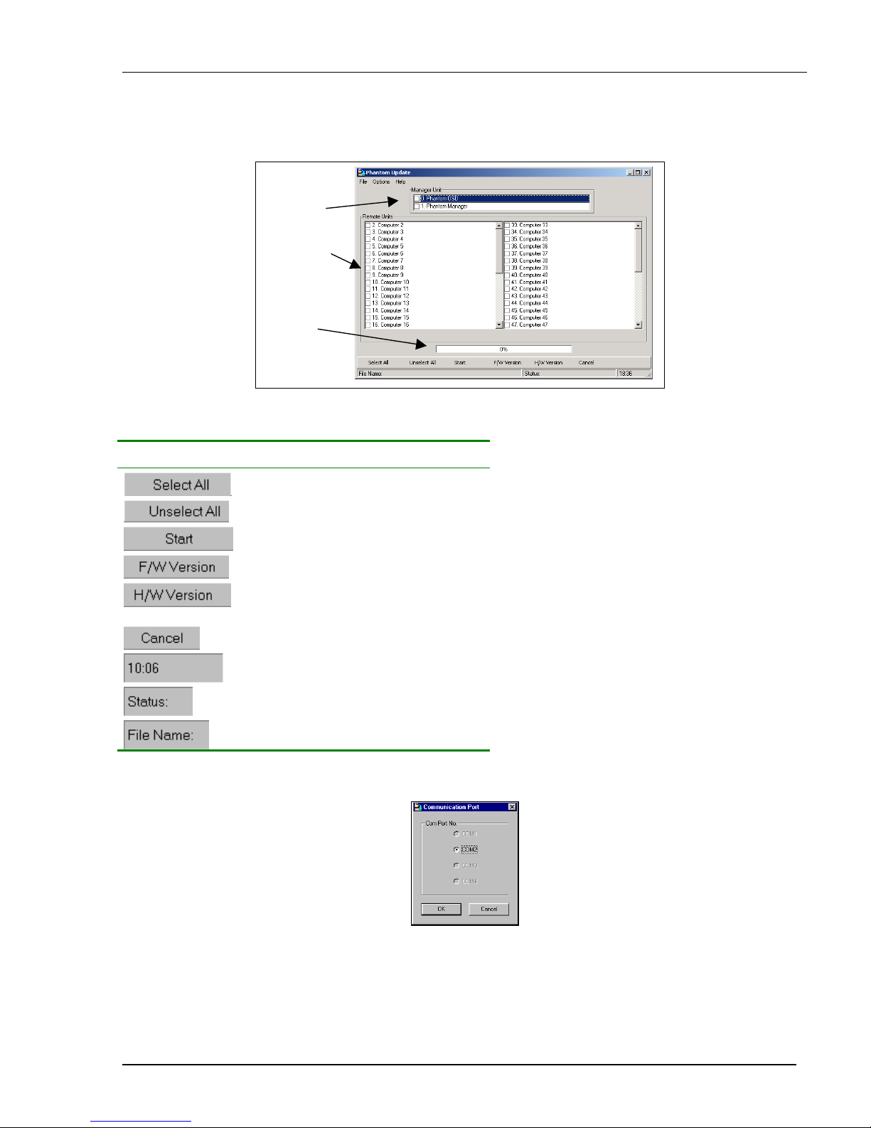
1. Start the Phantom Update software. The Phantom Update window appears. See Figure 6-1.
Remote
computers
Manager
box
Status
box
Figure 6-1 The Phantom Update window
The table below explains the functions of the buttons and boxes in the Phantom Update window.
Button or Box Function
Selects all remote computers
Unselects selected remote computers
Starts firmware download
Displays the firmware version number
Displays the hardware version
number
Cancels selected function
System time
Displays download status
Name of Update file
2. From the Options menu choose Com Port. The Com Port box appears. See Figure 6-2.
Figure 6-2 The Com Option box
3. Choose an available Com Port and click OK.
Note! The RS232 Serial cable must be connected to the selected Serial port.
Page 36
Upgrading the Phantom firmware
6-3
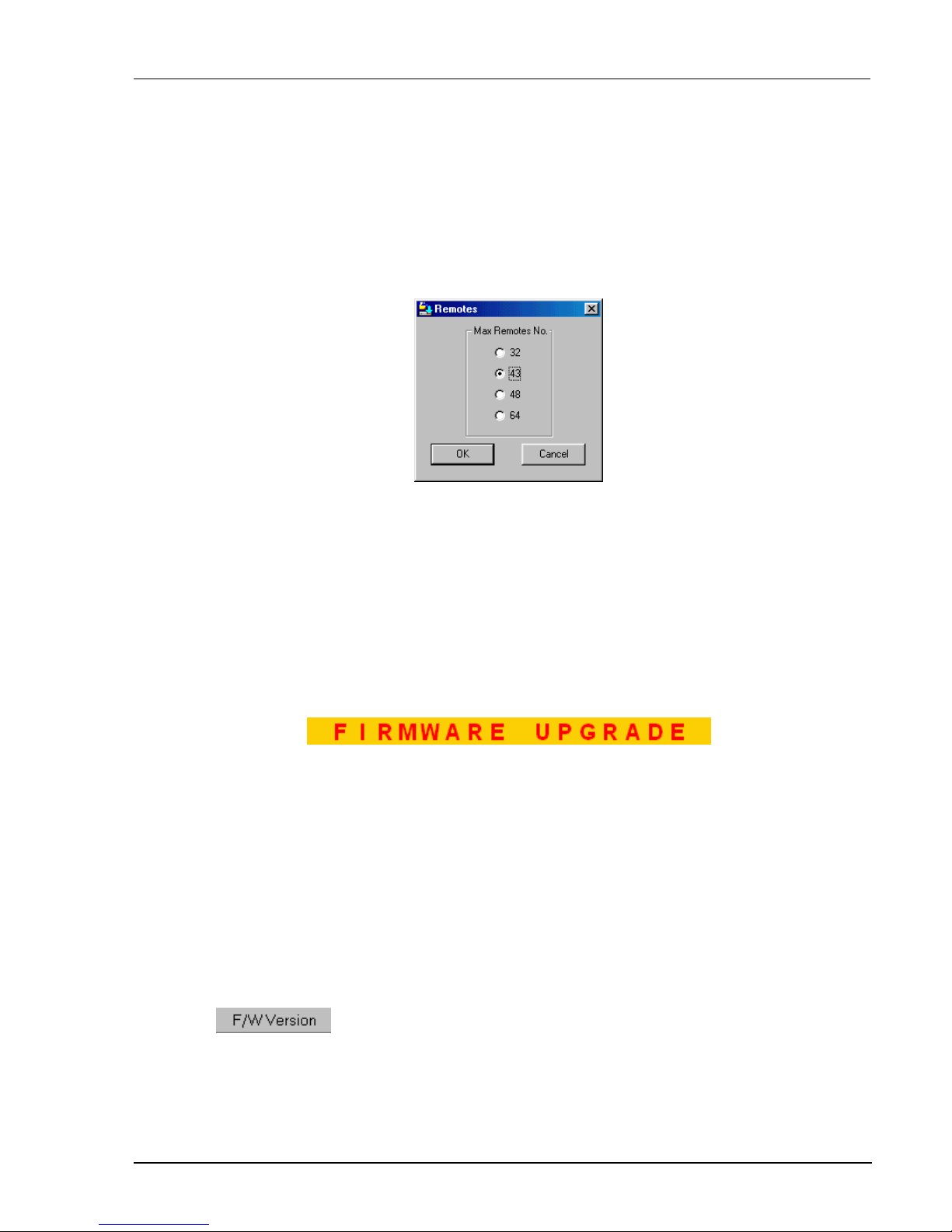
Displaying the maximum number of Remote units
Select the maximum number of Remote units to display in the Phantom Update window. By default 64 Remote
units are displayed.
1. From the Options menu choose Remotes. The Remotes box appears see Figure 6-3.
2. Select the maximum number of Remote units in your Phantom system.
3. Click OK.
Figure 6-3 The Remotes box
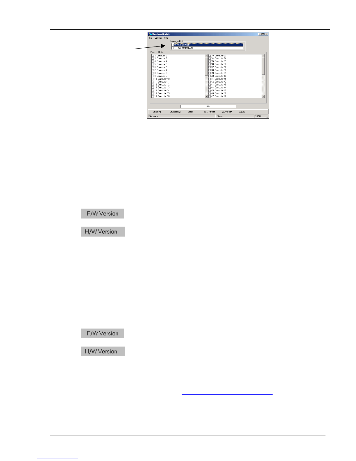
The F10 Upgrade hotkey
Whenever you use Phantom Update, you must first activate the Firmware Upgrade mode on the Phantom
Manager OSD.
To activate the Firmware Upgrade mode:
1. Display the Manager OSD window. The default Display hotkey is Shift, Shift.
2. Press F10. The Firmware Upgrade mode activates. The Firmware Upgrade label appears. See Figure 6-4.
Figure 6-4 The Firmware Upgrade label
Verifying the version numbers
Before upgrading the firmware, you must first verify which firmware and hardware versions you have.
The OSD version number
To verify the OSD version number:
1. Open the Phantom Update program.
2. Activate the Firmware Upgrade mode on the Manager OSD.
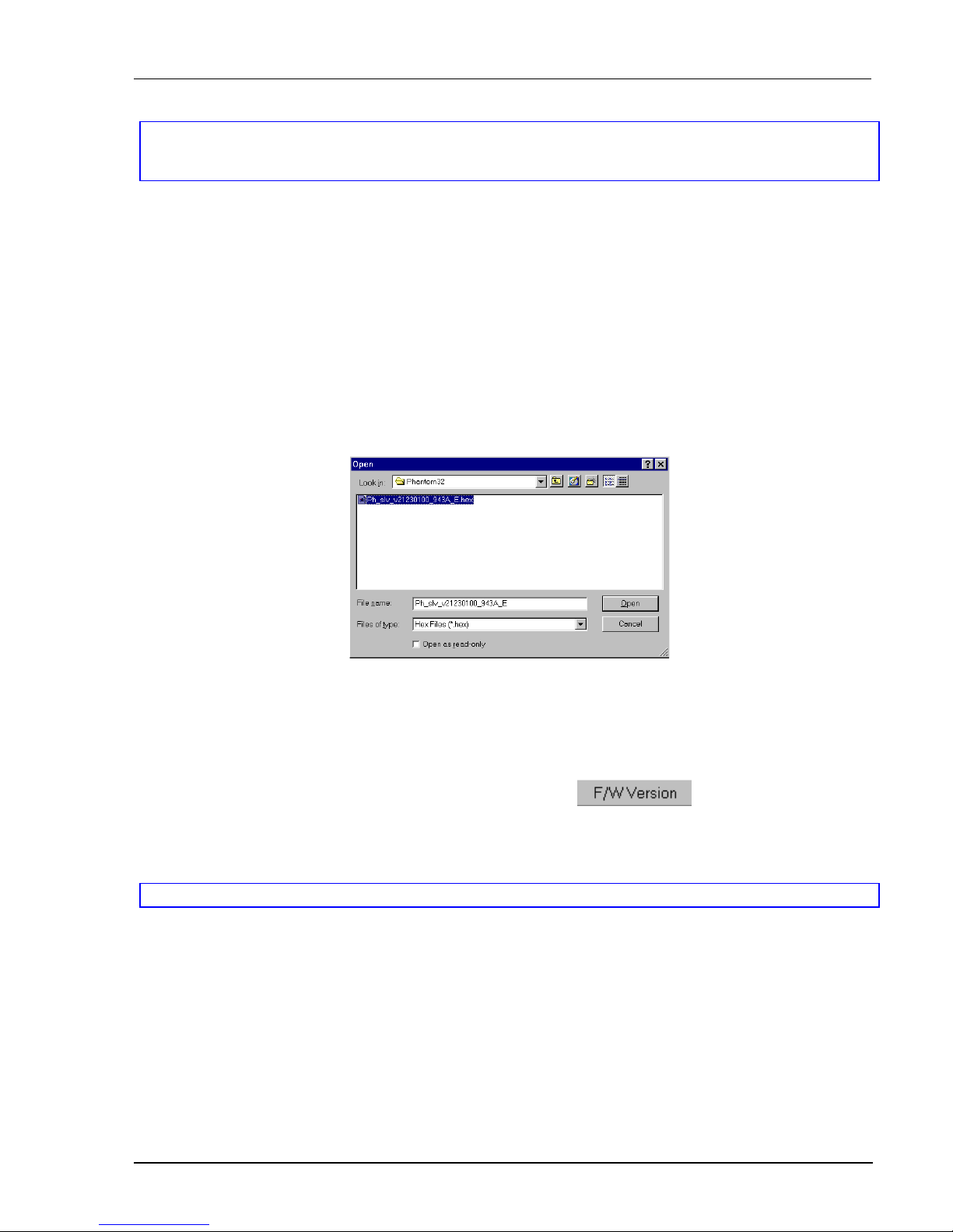
3. In the Manager Unit box, check the OSD option. See Figure 6-5 below.
4. Click
. The version number appears in the Manager box.
Page 37
Verifying the Remote version number
6-4
Manager
box
Figure 6-5 The OSD Manager option
The H/W Version button is grayed out, as there is no hardware relevant to the OSD.
The Phantom Manager version number
To verify the Phantom Manager version number:
1. Open the Phantom Update program.
2. Activate the Firmware Upgrade mode on the Manager OSD.
3. In the Manager Unit box, check the Phantom Manager option.
4. Click
. The firmware version number appears in the Manager Unit box.
5. Click
. The hardware version number appears in the Manager Unit box.
Verifying the Remote version number
Before you can check a remote computer, you must uncheck the Manager Unit box options.
To verify the Remote version number:
1. Open the Phantom Update program.
2. Activate the Firmware Upgrade mode on the Manager OSD.
3. Check one or more or all of the remote computers.
4. Click
. The firmware version number appears after the computer number.
5. Click
. The hardware version number appears after the computer number.
When “Not responding” appears, there is no computer connected, or it is switched off.
Obtaining new firmware
Download the latest firmware for your system from http://www.minicom.com/phandl.htm.
Page 38
Upgrading the Phantom firmware
6-5
Updating the firmware
Warning!
Never switch off any computer connected to the Phantom system during the updating process.
To update the firmware:
1. Open the Phantom Update program.
2. Activate the Firmware Upgrade mode on the Manager OSD.
3. In the Phantom Update window, check the appropriate option in the Manager Unit box or the desired
remote computer or computers.
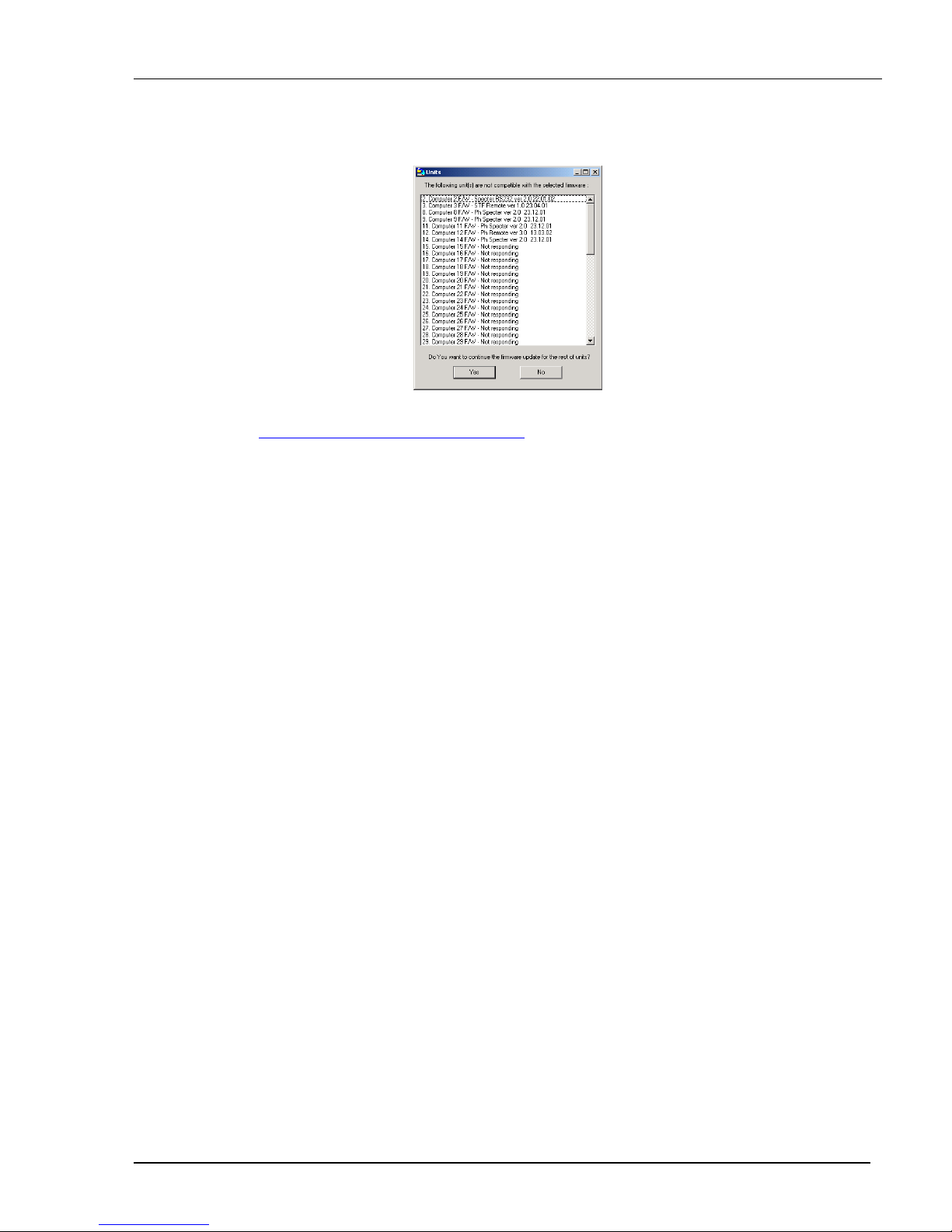
4. From the File menu, choose Open. The Open box appears. See Figure 6-6.
5. Navigate to the folder that contains the firmware update file. You may only see the files that match the file
selection mask.
Figure 6-6 The Mask for a Remote computer
6. Open the file.
7. Click Start. The Phantom Update flashes the firmware. On completion an Upgrade Successful message
appears.
8. Check that the updated version number is correct by pressing
.
Firmware Update generates one log file per session that displays a chronological list of actions. You can read
the log file in any ASCII text editor. The log file is located in the Windows directory.
Note! When you update the Manager firmware the OSD display hotkey reverts to Shift, Shift.
Page 39
Wrong firmware
6-6
Wrong firmware
When the firmware you are trying to flash is incompatible with the Phantom units a Not Compatible
message appears stating that some or all units are not compatible with the selected firmware.
Figure 6-7 The Not Compatible message
In this case go to http://www.minicom.com/phandl.htm for information on how to correctly identify
Phantom units.
All new Phantom units are protected from being updated with the wrong firmware. If you attempt to flash
them with incompatible firmware, an Upgrade Denied message appears and the Phantom unit continues
to function in the
Reset
Reset the software for the Phantom Manager or Remote units when for example the unit hangs or when the
mouse fails to work properly. Resetting is done via the Serial port, and avoids the need to shut down the
computer.
NOTE! The Reset function does not affect the parameters of the unit settings.
Resetting the Manager or Remote units
To reset the Manager or Remote units:
1. For the Manager, check the Phantom Manager option in the Manager Unit box.
For the Remotes, check one or more Remotes in the Remote Units box
2. From the Options menu choose Advanced / Reset. The units reset. The system should now be
operational.
Troubleshooting tips
When using Firmware Update software you may sometimes get a Communication Error message.
When updating a unit and a Communication Error message appears, do the following:
1. Check that the RS232 Serial cable’s RS232 connector is connected to the Manager’s Communication port.
2. Check that the RS232 Serial cable’s DB9F connector is connected to the DB9M Serial port on the CPU’s
rear panel.
3. Restart the download process from page 6-2, and make sure the Firmware Upgrade mode is activated.
Page 40

Upgrading the Phantom firmware
6-7
Electricity failure
When the electricity fails while updating the Phantom firmware, do the following:
If the electricity fails during the firmware update of the Manager, a Communication Error message appears.
The Phantom Manager enters the Upgrade mode automatically without displaying the Firmware Upgrade label.
Simply resume the firmware update by opening the folder that contains the firmware update file and continue
from there.
If the electricity fails during the firmware update of the Remote units a Not Responding or Upgrade Error
message appears. Restart the upgrade from the beginning.
Should the update fail to work go to http://www.minicom.com/phandl.htm
and download the Technical memos
that explain the firmware restoration techniques
Page 41

Phantom Specter USB SUN Combo keys
A-1
Appendix A: Phantom Specter USB SUN Combo
keys
The SUN keyboard consists of a special keypad to perform special functions in the SUN Operating System
environment. A PS/2 keyboard connected to the Phantom Manager does not have a corresponding keypad, so the
Phantom USB emulates these keys using a set of key combinations called Combo keys. See the table below.
SUN key Combo key
Stop Left Ctrl + Alt + F1
Props Left Ctrl + Alt + F3
Front Left Ctrl + Alt + F5
Open Left Ctrl + Alt +F7
Find Left Ctrl +Alt + F9
Again Left Ctrl + Alt + F2
Undo Left Ctrl + Alt + F4
Copy Left Ctrl + Alt + F6
Paste Left Ctrl + Alt + F8
Cut Left Ctrl + Alt + F10
Help Left Ctrl + Alt + F11
Compose
Application key or Left Ctrl + Alt + Keypad *
Crescent
Scroll Lock
Vol u me U p Left Ctrl + Alt + Keypad –
Vol u me D o w n Left Ctrl + Alt + Keypad +
Mute Left Ctrl + Alt + F12
Sun Left ◊ key Left Windows key
Sun Right ◊ key Right Windows key
Alt-Graph Right Alt or Alt Gr
Stop A Left Ctrl + Alt + 1
 Loading...