

Page 1
www.minicom.com
International HQ
Jerusalem, Israel
Tel: + 972 2 535 9666
North American HQ
Linden, NJ, USA
Tel: + 1 908 486 2100
European HQ
Dübendorf, Switzerland
Tel: + 41 44 823 8000
Technical support - [email protected]
5UM20143 V1.9 8/07
Smart IP Access
User Guide
Page 2

SMART IP ACCESS
1
Table of Contents
1. Welcome..........................................................................................................3
2. Introduction.....................................................................................................3
3. Key Features...................................................................................................4
4. System components.......................................................................................4
5. The Smart IP Access unit...............................................................................5
6. Pre-installation guidelines..............................................................................6
6.1 Avoiding general rack mounting problems..........................................................6
6.2 Rack mounting the IP Access...............................................................................7
7. Terminology....................................................................................................7
8. Client computer operating system.................................................................7
9. Connecting the system...................................................................................7
10. Default IP address.........................................................................................9
11. Logging into the Web interface..................................................................10
11.1 SSL Certificate notes........................................................................................11
12. Network > Configuration.............................................................................11
12.1 LAN 1.................................................................................................................12
12.2 KVM.net.............................................................................................................12
13. Network > SNMP settings...........................................................................13
14. Administration > User Settings..................................................................13
14.1 Administrator....................................................................................................14
14.2 User...................................................................................................................14
14.3 View only...........................................................................................................14
14.4 Adding a user....................................................................................................14
14.5 Editing a user....................................................................................................15
14.6 Deleting a user..................................................................................................15
14.7 Blocking a user.................................................................................................15
15. Administration > Switch configuration......................................................15
16. Administration > Serial Settings.................................................................16
16.1 Show..................................................................................................................17
17. Security > Settings......................................................................................17
18. Security > SSL certificates.........................................................................18
19. Security > Event Log...................................................................................19
20. Maintenance > Set System Time................................................................19
21. Maintenance > Firmware Upgrade..............................................................20
22. Maintenance > Restore Factory Settings...................................................20
23. Saving changes and logging out................................................................21
Page 3

USER GUIDE
2
24. Starting a remote session...........................................................................21
24.1 Taking over a busy remote session..................................................................22
24.2 Full screen mode...............................................................................................22
24.3 Moving or hiding the Toolbar............................................................................23
24.4 Switching to a different server/device..............................................................23
24.5 Changing the performance settings.................................................................24
24.6 Adjusting the Video settings.............................................................................25
24.6.1 Refresh.......................................................................................................25
24.6.2 Manual Video Adjust....................................................................................25
24.6.3 Auto Video Adjust........................................................................................26
24.7 Power cycle.......................................................................................................26
24.8 Keyboard key sequences..................................................................................26
24.9 Synchronizing mouse pointers.........................................................................28
24.9.1 Aligning the mice pointers............................................................................28
24.9.2 Calibrating mice pointers..............................................................................28
24.9.3 Manual mice synchronization.......................................................................29
24.10 Minicom logo menu features..........................................................................30
24.11 Disconnecting the remote session.................................................................31
25. Troubleshooting - Restoring factory defaults............................................31
26. Technical Specifications.............................................................................34
27. Video Resolution and Refresh Rates.........................................................35
28. Safety...........................................................................................................35
29. User Guide Feedback..................................................................................35
30. WEEE Compliance......................................................................................36
© 2007 Copyright Minicom Advanced Systems. All rights reserved.
Page 4

SMART IP ACCESS
3
1. Welcome
Thank you for buying the Smart IP Access system. This system is produced by
Minicom Advanced Systems Limited.
This document provides installation and operation instructions for Minicom’s
Smart IP Access. It is intended for system administrators and network managers,
and assumes that readers have a general understanding of networks, hardware and
software.
Technical precautions
This equipment generates radio frequency energy and if not installed in accordance
with the manufacturer’s instructions, may cause radio frequency interference.
This equipment complies with Part 15, Subpart J of the FCC rules for a Class A
computing device. This equipment also complies with the Class A limits for radio
noise emission from digital apparatus set out in the Radio Interference Regulation
of the Canadian Department of Communications. These above rules are designed to
provide reasonable protection against such interference when operating the
equipment in a commercial environment. If operation of this equipment in a
residential area causes radio frequency interference, the user, and not Minicom
Advanced Systems Limited, will be responsible.
Changes or modifications made to this equipment not expressly approved by
Minicom Advanced Systems Limited could void the user’s authority to operate the
equipment.
Minicom Advanced Systems Limited assumes no responsibility for any errors that
appear in this document. Information in this document is subject to change without
notice.
No part of this document may be reproduced or transmitted in any form or by any
means, electronic or mechanical, for any purpose, without the express written
permission of Minicom Advanced Systems Limited.
Trademarks
All trademarks and registered trademarks are the property of their respective
owners.
2. Introduction
The Smart IP Access extends your KVM (keyboard, video, mouse) from any
computer or server over TCP/IP via LAN, or WAN. Now you can control, monitor
and manage your servers from wherever you are, inside or outside the organization.
The Smart IP Access is a cost-effective hardware solution, for secure remote KVM
access & control of a computer/server from the BIOS level - independent of the
OS. It is designed to connect to a single computer or to a KVM switch to access
Page 5

USER GUIDE
4
multiple servers, over TCP/IP communication.
3. Key Features
BIOS level access to any server’s brand and model, regardless of the server
condition and network connectivity, covering the entire spectrum of crash
scenarios.
Low bandwidth requirement. Provides a unique ability to utilize a standard
56Kbps analog modem connection, while allowing adaptive and configurable
bandwidth consumption when accessed via LAN.
Compatible with all major operating systems. Supports many hardware and
software configurations for the remote client and the target server computers, as
well as the KVM switch in use.
Web-based Access - Browser access to a target server, from any location via
secured standard IP connection.
SNMP - SNMP traps for monitoring Smart IP Access events and operation.
Multi-user view mode - Allows simultaneous users to view remote sessions.
Remote control can be intuitively handed between users with appropriate
permissions.
4. System components
The Smart IP Access system consists of:
· 1 Smart IP Access (p/n 1SU51068)
· 3 in 1 CPU cable (p/n 5CB10477)
· 1 RS232 Cross cable (p/n 5CB00566)
· Rack-mount kit (p/n 5AC20255)
The RS232 Cross cable connects the Smart IP Access to Serial manageable devices
such as Power Management units, Routers, etc.
RS232 Cross cable option
Smart IP Access has two RS232 RJ45 connectors. You can purchase another
RS232 Cross cable to connect a second Serial device. P/N 5CB00566
Page 6
SMART IP ACCESS
5
5. The Smart IP Access unit
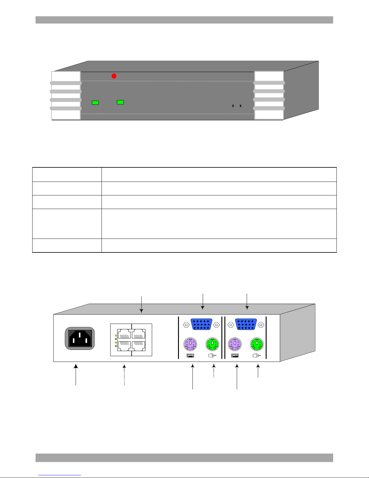
Figure 1 illustrates the front panel of the Smart IP Access.
MINICOM
SMARTIPACCESS
PowerRemote ResetLocal
Figure 1 Smart IP Access front panel
The table below lists the LEDs, buttons and functions.
LED/Button Function
Power Power Indicator
Remote Illuminates when remote session is active
Local When pressed, Smart IP Access disconnects the Client computer’s
link to the Target Server, and the Local Mouse and Keyboard become
operational.
Reset Restarts the Smart IP Access unit
The figure below illustrates the rear panel of the Smart IP Access.
Power
connector
Keyboard
Mouse
Monitor
Computer
Keyboard port
Computer
Mouse port
Computer
Video card
LAN 1 and 2
Ethernet
connectors
SERIAL 1 and 2
RS232
connectors
POWER
100-240 VAC 50/60 Hz
www.minicom.com
CONSOLECOMPUTER
22
11
L
A
N
S
E
R
I
A
L
Figure 2 Smart IP Access rear panel
The table below lists the rear connectors and functions.
Page 7

USER GUIDE
6
Connector Function
Computer KVM Connect a computer or KVM switch
Console KVM Connect a keyboard, video and mouse to operate the Smart IP
Access locally
Serial 1 and 2 RS232 Connect to an RS232 device
LAN 1 and 2 Connect to 10/100 Mbit Ethernet
6. Pre-installation guidelines
Place cables away from fluorescent lights, air conditioners, and machines that are
likely to generate electrical noise.
Place the Smart IP Access on a flat, clean and dry surface.
The Smart IP Access is not intended for connection to exposed outdoor lines
6.1 Avoiding general rack mounting problems
Elevated operating ambient temperature
The operating ambient temperature of the rack environment may be greater than
the room ambient when installing into a closed or multi-unit rack assembly. So
install the equipment in an environment compatible with the maximum rated
ambient temperature.
Reduced airflow
Install the equipment in a rack in such a way that the amount of airflow required
for safe operation is not compromised. Leave a gap of at least 5cm/2” each side of
the Smart IP Access.
Mechanical loading
Mount the equipment in the rack in such a way that a hazardous condition is not
achieved due to uneven mechanical loading.
Circuit overloading
When connecting the equipment to the supply circuit, consider the effect that
overloading of circuits might have on over-current protection and supply wiring.
Reliable earthing of rack-mounted equipment should be maintained. Give attention
to supply connections other than direct connections to the branch circuit (e.g. use of
power strips).
Page 8
SMART IP ACCESS
7
6.2 Rack mounting the IP Access
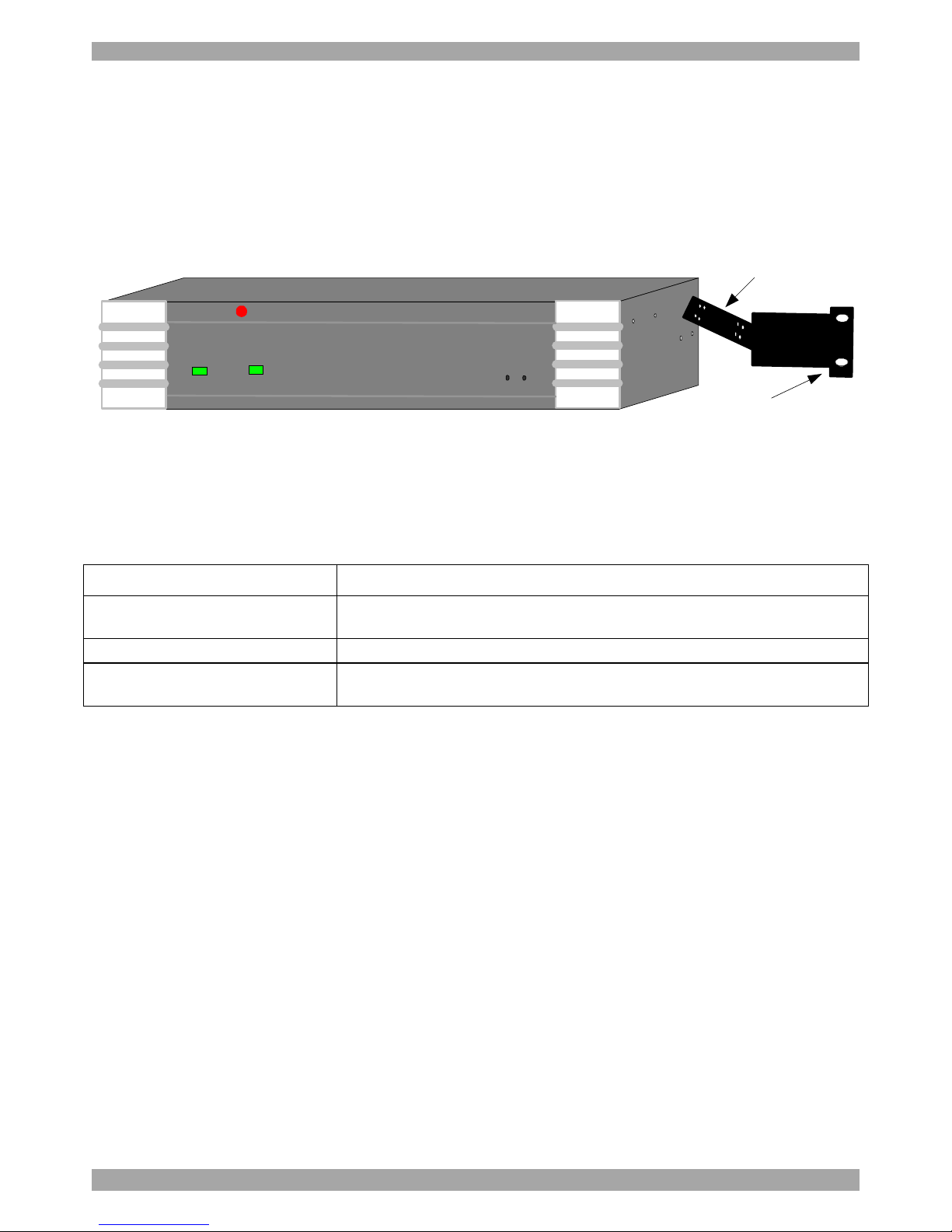
Rack mount the Smart IP Access using the supplied Rack-mount kit. There are 2
possible positions on the side of the Smart IP Access to connect the bracket. Screw
the bracket to the Smart IP Access using 2 screws. See Figure 3. Screw the other
bracket section to the rack.
MINICOM SMARTIPACCESS
PowerRemote ResetLocal
Screw this section
to side of Smart IP
Access
Screw this section
to the rack
Figure 3 Rack mounting the Smart IP Access
7. Terminology
Below are some terms and their meanings used in this guide.
Term Meaning
Target Server The computers/servers that are accessed remotely via the Smart IP
Access.
Client computer The PC running a remote Smart IP Access session
Remote Session The process of accessing and controlling Target Servers connected
to Smart IP Access from a User station
8. Client computer operating system
Windows NT4.0, 2000, XP or 2003 Server, with IE 6.0 or higher. 128 bit
encryption is required if a secured connection is selected.
9. Connecting the system
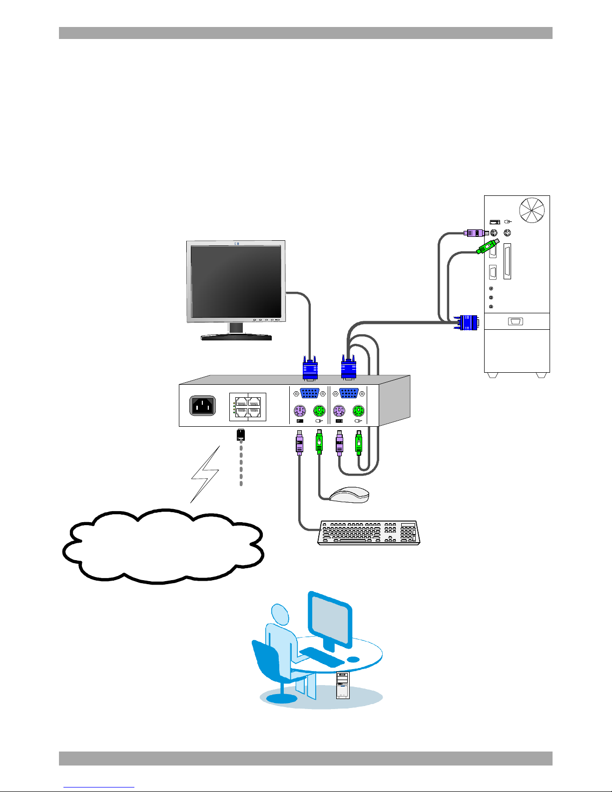
Connect the Target Server / KVM switch to the Smart IP Access as follows:
1. Connect one end of the 3 in 1 CPU cable to the Computer ports of the Smart IP
Access.
2. Connect the other end of the 3 in 1 CPU cable to the KVM ports of the Target
Server / KVM switch.
3. To operate the KVM switches and Servers locally, connect a keyboard, mouse
and monitor to the IP Access’s Local Console connectors.
Page 9
USER GUIDE
8
4. Connect Smart IP Access to the network by attaching one of the LAN ports to
an Ethernet port on your Network. IP Access has two LAN interfaces – see
Initial Settings
5. Connect to the power supply using the power cord provided.
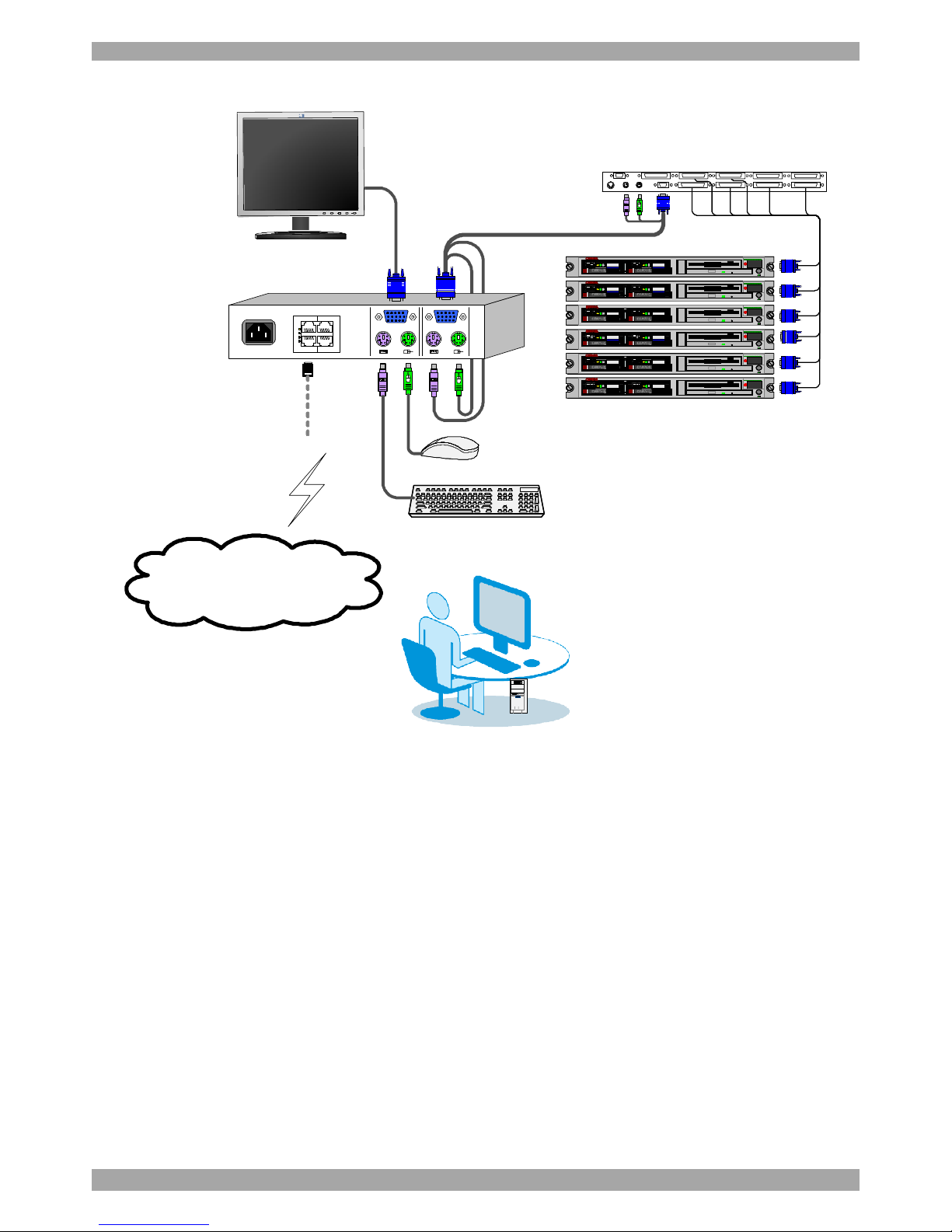
Figure 4 and Figure 5 illustrate the connections to a computer and KVM switch
respectively, with the optional KVM console.
3 in 1 CPU cable
Target PC
POWER
100-240 VAC 50/60 Hz
www.minicom.com
CONSOLECOMPUTER
22
11
L
A
N
S
E
R
I
A
L
User over IP
hp1925
Auto12
LAN / WAN
Figure 4 Smart IP Access connections to a computer
Page 10
SMART IP ACCESS
9
Computerrack
ProLiantDL360
9.1-GB10k
ULTRA2SCSI
9.1-GB10k
ULTRA2SCSI
ProLiantDL360
9.1-GB
10k
ULTRA2SCSI
9.1-GB
10k
ULTRA2SCSI
ProLiantDL360
9.1-GB
10k
ULTRA2SCSI
9.1-GB
10k
ULTRA2SCSI
ProLiantDL360
9.1-GB
10k
ULTRA2SCSI
9.1-GB
10k
ULTRA2SCSI
ProLiantDL360
9.1-GB10k
ULTRA2SCSI
9.1-GB10k
ULTRA2SCSI
ProLiantDL360
9.1-GB
10k
ULTRA2SCSI
9.1-GB
10k
ULTRA2SCSI
COMPUTER1COMPUTER2
COMPUTER6COMPUTER5STATION2
SCREENPS/2MOUSEKB
POWER
SERIALMOUSE
COMPUTER3COMPUTER4
COMPUTER8COMPUTER7
KVMswitch
3 in 1 CPU cable
POWER
100-240 VAC 50/60 Hz
www.minicom.com
CONSOLECOMPUTER
22
11
L
A
N
S
E
R
I
A
L
User over IP
hp1925
Auto12
LAN / WAN
Figure 5 Smart IP Access connections to a KVM switch
10. Default IP address
Smart IP Access has two available Ethernet Adapters, LAN 1 and LAN 2:
· By default, LAN 1 boots with an automatically assigned IP address if a
DHCP (Dynamic Host Configuration Protocol) server exists. The MAC
address appears on a label on the underside of the IP Access box. Also on
the label is the 6-digit device number (D.N.). The default device name is
the letter ‘D’ followed by the device number
· LAN 2 boots with the default IP configuration:
IP Address - 192.168.0.155
Subnet mask - 255.255.255.0
You can use the default Smart IP Access IP address if your computer resides on the
same subnet where Smart IP Access is installed, or you can connect a Crossover
Page 11
USER GUIDE
10
LAN connector cable to the Smart IP Access on one end, and to the Ethernet
adapter of your computer at the other end.
11. Logging into the Web interface
To complete the initial setup via the Web configuration interface:
1. Open your Web browser (Internet Explorer version 6.0 or higher)
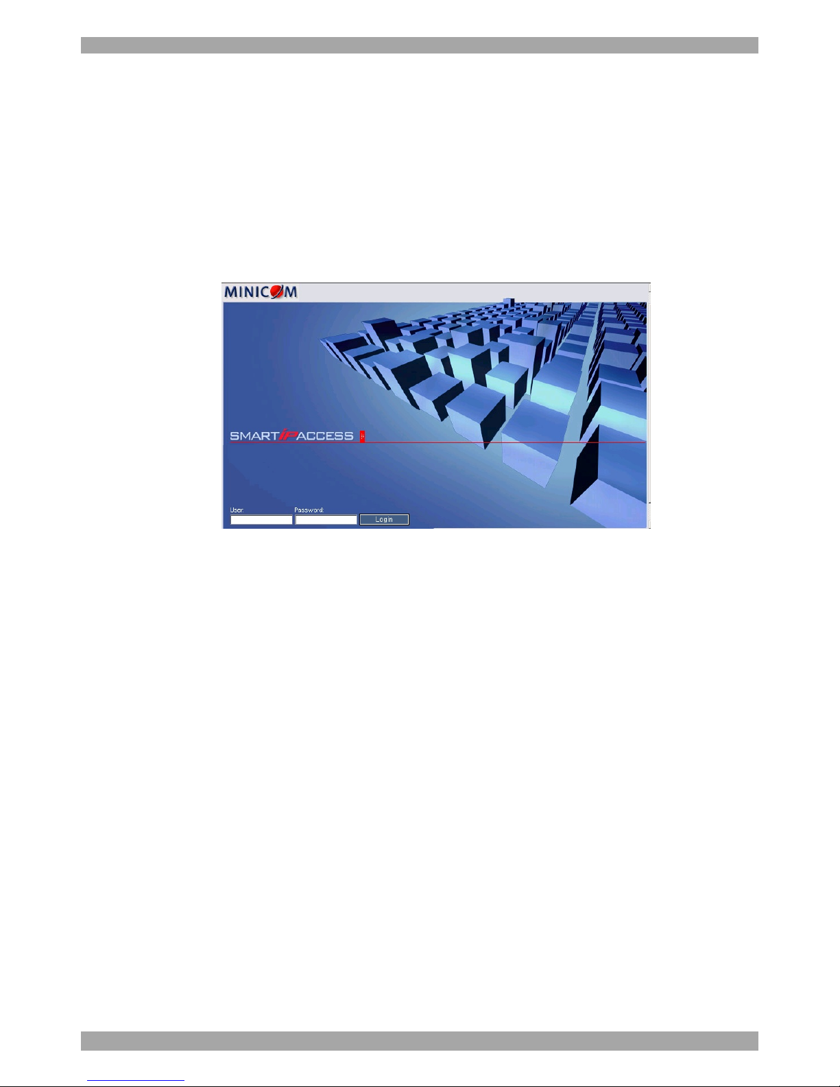
2. Type the IP address of the Smart IP Access system - https://IP address/config
and press Enter. The login page appears, see Figure 6
Figure 6 Login page
3. Type the Administrator user name and password. By default, the user name is:
admin and the password is access (both lower case).
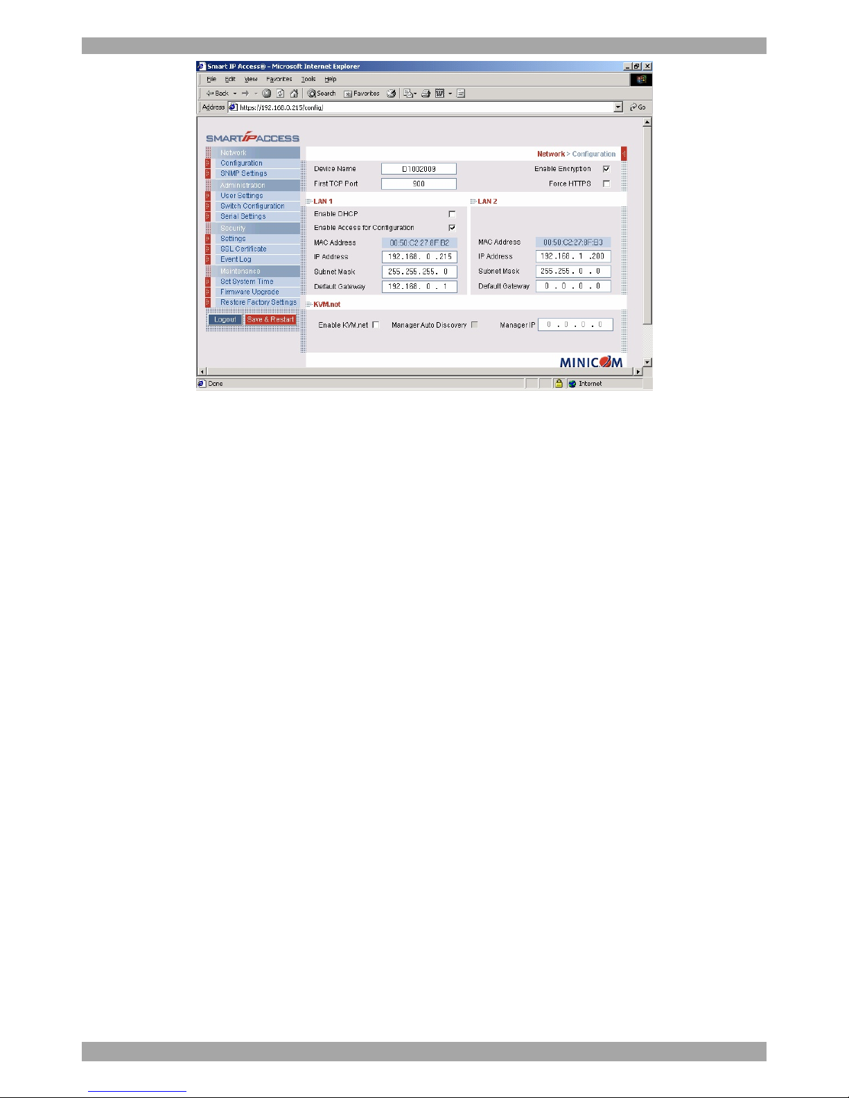
4. Press Enter. The Web interface opens at the Network Configuration page. See
Figure 7.
5. Bookmark the page for easy reference.
Page 12
SMART IP ACCESS
11
Figure 7 Smart IP Access Web interface
11.1 SSL Certificate notes
Upon first connection to Smart IP Access’s https Configuration page, 2 browser
security warnings appear. Click Yes to proceed.
The first warning disappears upon first Smart IP Access client installation, once
Minicom’s root certificate is installed.
12. Network > Configuration
Consult your Network Administrator for the network settings.
Device name - Type the name for the Smart IP Access. Default device name
consists of the letter ‘D’ followed by the 6-digit device number (D.N.) found on the
silver label on the underside of the IP Access box.
First TCP Port - Choose 3 consecutive ports, and type in the first port number of
the series. The default port – 900 – is suitable for the majority of installations.
Note
Firewall or router security access list must enable inbound communication through
the selected TCP ports for the Smart IP Access’s IP address.
For Client computer access from a secured LAN, the selected ports should be open
for outbound communication.
Enable Encryption - Enable Encryption if you wish to operate in a secure
connection (recommended).
Page 13

USER GUIDE
12
If enabled, the Internet Explorer at the Client computer must support 128 bit
Encryption.
Force HTTPS - Access the Web front-end only using an HTTPS connection.
Smart IP Access won't listen on the HTTP port for incoming connections.
12.1 LAN 1
Under LAN 1 in Figure 7, is the following:
Enable DHCP – When a DHCP server is active on the same network to which
Smart IP Access is connected, DHCP provides automatic IP assignment.
When DHCP is disabled – (Recommended) – You can assign a fixed IP address to
the Smart IP Access.
Consult your Network Administrator regarding the use of the DHCP. Note! Where
you have access to the DHCP server– your configured (or default) Smart IP Access
device name will appear on the DHCP server’s interface, making it easy to locate.
Enable Access for Configuration - Click to enable access to the configuration
menu from the LAN 1. If disabled, a remote session can only be performed via
LAN 1 and the Web configuration menu can only be accessed from LAN 2. This
may be useful when dedicating LAN 2 to LAN access only, to enhance security.
When DHCP is disabled, enter an IP Address, Subnet Mask, and Default
Gateway for LAN 1 and 2, as given by your Network Administrator.
12.2 KVM.net
KVM.net is a centralized IP based system for secure control of servers and
network devices, power and user administration in the data center environment.
KVM.net combines Out-Of-Band, KVM via IP access with modern IT standards
and requirements. It is the most comprehensive remote server maintenance solution
available in the market today.
Enable KVM.net - Check this option to allow Smart IP Access unit to be remotely
managed by Minicom’s KVM.net system.
Manager Auto Discovery – when checked, KVM.net automatically detects Smart
IP Access, if it resides on the same network segment.
Manager IP – If Smart IP Access resides on a different segment, type the static IP
address of the KVM.net Manager. (We advise typing the static IP address of the
KVM.net Manager even if the Smart IP Access resides on the same network
segment as the KVM.net Manager).
Page 14
SMART IP ACCESS
13
13. Network > SNMP settings
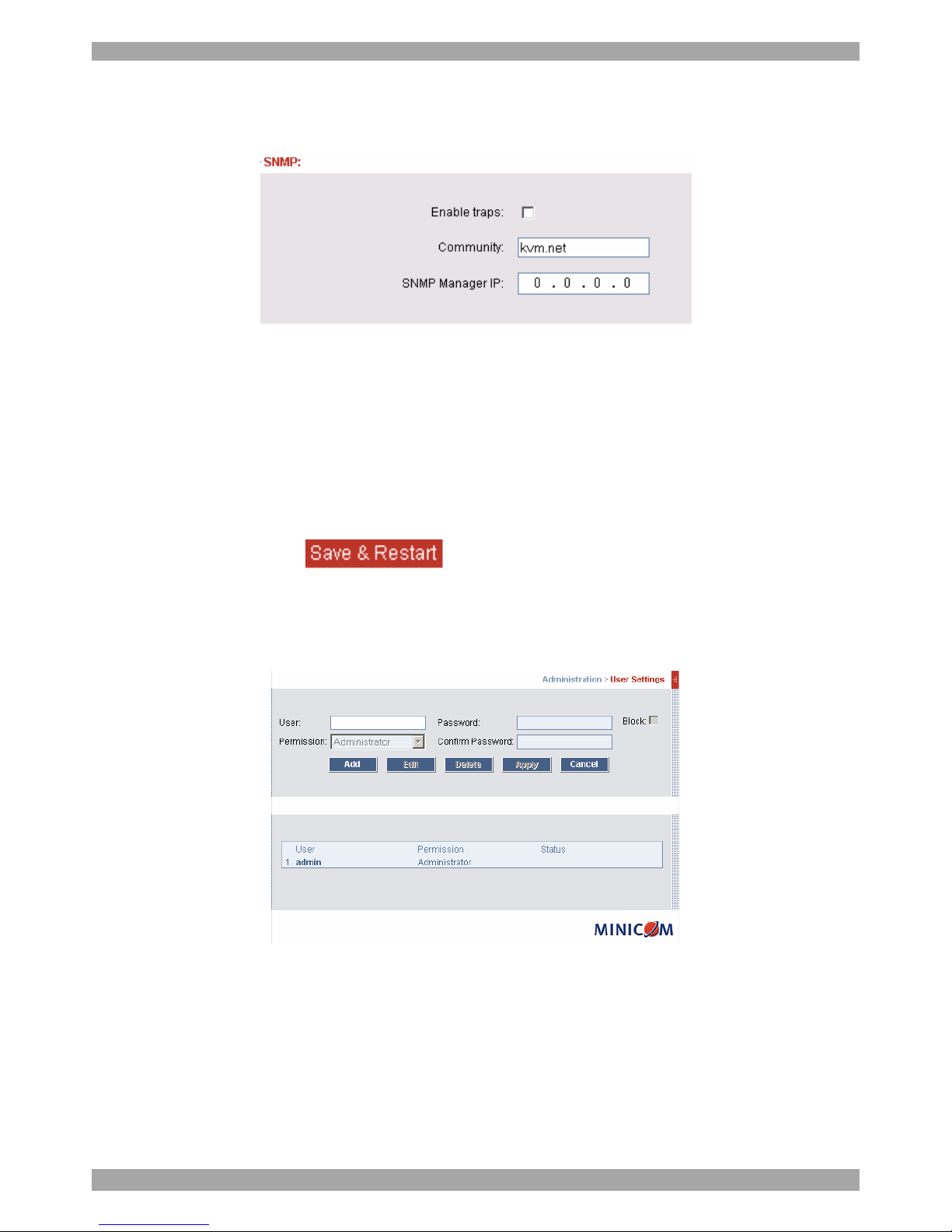
From the menu click SNMP settings. The following appears.
Figure 8 SNMP settings
From this page you can activate or deactivate SNMP logging.
Enable traps - Check to enable SNMP traps of Smart IP Access events and
operation.
Community – type the SNMP community
SNMP Manager IP - Enter the SNMP Server IP address
To save changes, click .
14. Administration > User Settings
From the menu click User Settings, the following appears.
Figure 9 User Settings
On this page an Administrator creates and edits users.
There are 3 levels of user access.
· Administrator
· User
· View only
Page 15
USER GUIDE
14
14.1 Administrator
An Administrator has unrestricted access to all windows and settings and can “take
over” any active session. An Administrator can change the name and password of
all users.
14.2 User
A User has no access to the Web configuration interface. When accessing a Target
Server a User cannot use the following:
· Advanced mouse settings
· Power cycle
14.3 View only
View only can view the screen of any Target Server without keyboard and mouse
control. Only limited options appear such as switching Servers and Disconnect
(Explained on pages23 and 31). A “view only” indicator appears on the viewer’s
local mouse pointer.
14.4 Adding a user
To add a user:
1. Click and type a name and a password. The password must be at
least 6 characters – letters or numbers, and must not include the user name, even
if other characters are added.
Note! The following “special” characters: &, <, >, ”, {, } cannot be used for
either the user name or password.
Depending on the security level chosen the user name and password parameters are
different. See section 17 on page 17.
2. Select the permission type from the Permission box.
3. Click , the user appears in the list of users.
Page 16
SMART IP ACCESS
15
14.5 Editing a user
To edit a user:
1. Select the user from the list.
2. Click . You can now change all the parameters – user name,
permission and password.
3. Click , the changes are saved.
14.6 Deleting a user
To delete a user:
1. Select the user from the list.
2. Click .
3. Click , the changes are saved.
14.7 Blocking a user
An alternative to deleting a user is blocking a user. This means that the user’s name
and password is stored, but the user is unable to access the system. Check Block to
block a user. Uncheck Block to allow the user access.
15. Administration > Switch configuration
When a KVM switch is connected to the system, you must configure the switch in
the system.
To do so:
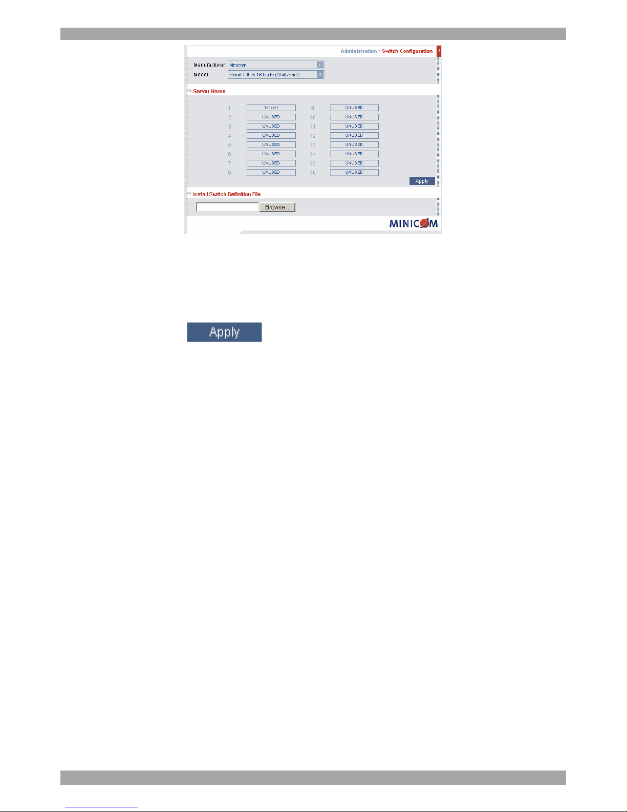
1. From the menu click Switch Configuration. The KVM Switch Configuration
window appear, see Figure 10.
Page 17
USER GUIDE
16
Figure 10 Switch configuration
1. Choose the manufacturer and model of the connected KVM switch. The number
of possible connected servers appears in the Server Name section.
2. Change the name of the connected servers by selecting the server and typing a
new name. Click to save changes.
Note! Server names left as UNUSED cannot be accessed.
Install switch definition file
Where the KVM switch type is not listed in the manufacturer/model drop-down
lists, contact Minicom to request an updated Switch Definition file with the desired
KVM switch listed.
1. Load the file onto the Client computer.
2. Locate and install the KVM switch definition file. The switch definition file is
updated.
16. Administration > Serial Settings
Where you have a Serial device connected to the system you must configure the
RS232 settings.
To do so:
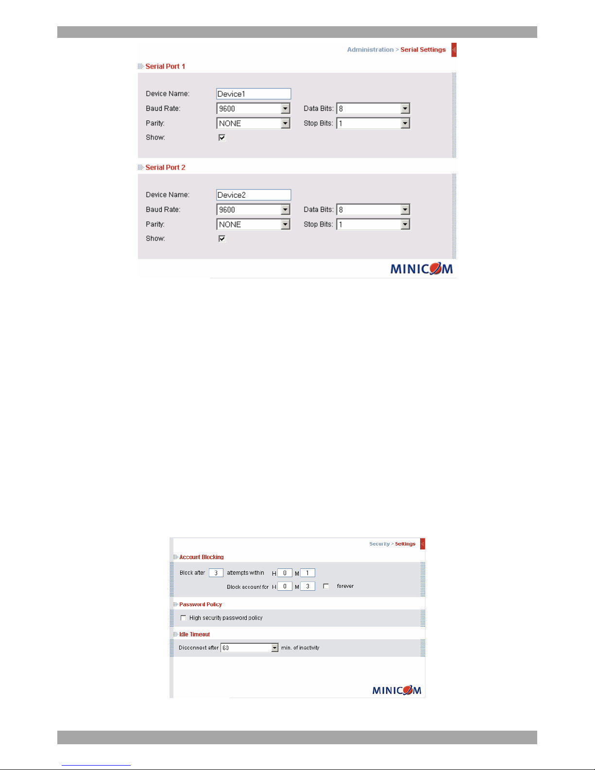
From the menu click Serial Settings, the Serial Settings appear, see Figure 11.
Page 18
SMART IP ACCESS
17
Figure 11 Serial Settings
For both Serial ports (where relevant), type in a device name and choose the correct
device parameters.
16.1 Show
Tick Show to make the device appear in the list of servers/devices that can be
accessed. Where there is no device connected to the particular Serial port uncheck
Show.
17. Security > Settings
Configure the security features, such as Account Blocking, Password Policy and
Idle Timeout, as explained below.
From the Security section click Settings, the Security Settings appear, see Figure
12.
Figure 12 Security Settings
Page 19
USER GUIDE
18
The security page elements:
Account Blocking – decide on the number of attempts to login with a wrong
username or password after which there is a time lock or a total block.
Password Policy – You have the option of a standard or high security level of
password. The table below shows the parameters of the 2 options.
Standard Security Password High security Password
6 characters or more 8 characters or more must
include at least 1 digit and 1
upper case letter and 1 “special”
character as follows
!@#$%^*()_-+=[]’:;?/
Must not include the user name Must not include the user name
Check the box to enable the high security password policy. Unchecked, the
standard security policy applies.
Idle Timeout – Select the Timeout inactivity period after which the user is
disconnected from the system. Timeout can also be disabled.
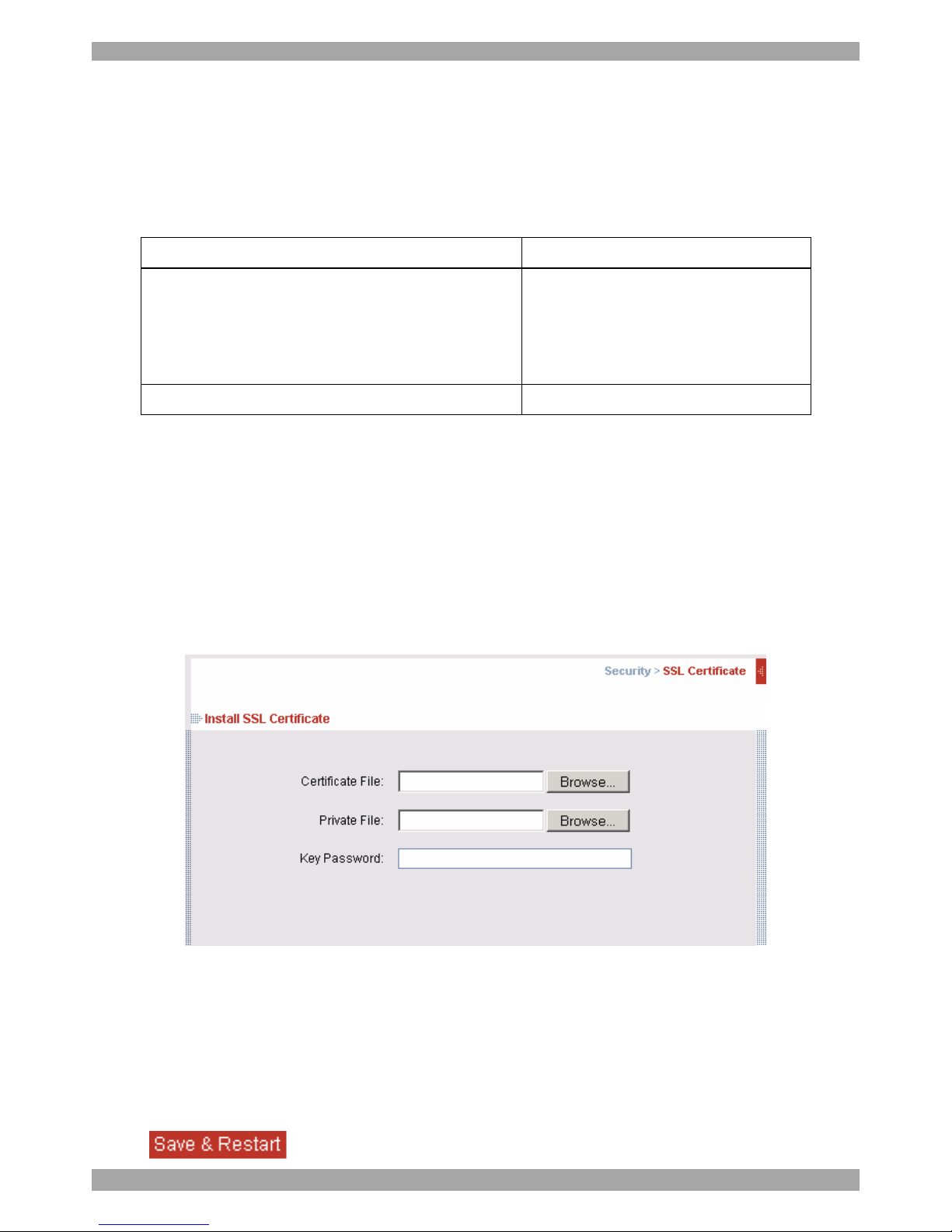
18. Security > SSL certificates
From the menu, select SSL Certificate, the SSL Certificate page appears, see
Figure 13.
Figure 13 The SSL Certificate page
You can replace the current Smart IP Access’s SSL certificate.
Certificate File - Browse to locate the cer file.
Private File - Browse to locate the private key file.
Key Password - Type the “private key” password.
Click .
Page 20
SMART IP ACCESS
19
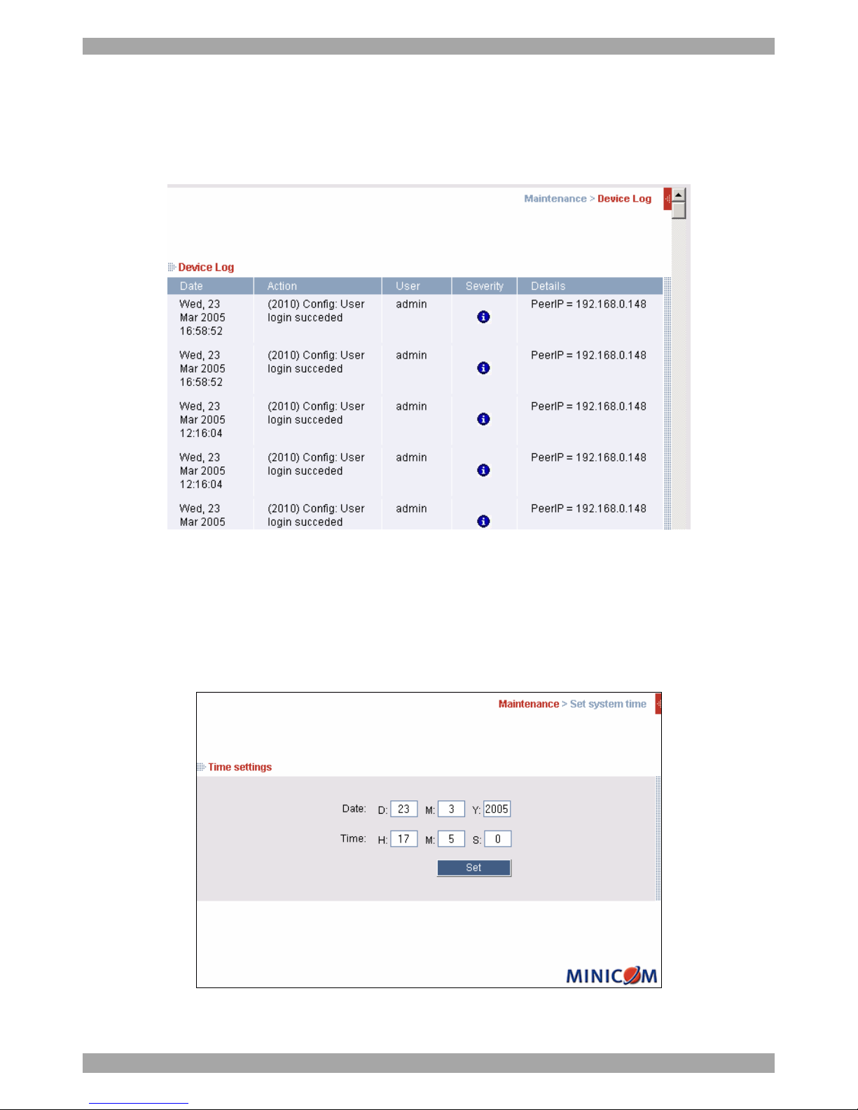
19. Security > Event Log
From the menu select Event Log. The Event Log page appears, see Figure 14.
Here you can view the device log, recording various events: security alerts, system
alerts, configuration changes, and user activity.
Figure 14 Event log
20. Maintenance > Set System Time
From the menu select Set System Time. The Time Settings page appears see
Figure 15. Set the correct date and time for Smart IP Access so that the logs record
the correct time of the events.
Figure 15 Time Settings
Page 21
USER GUIDE
20
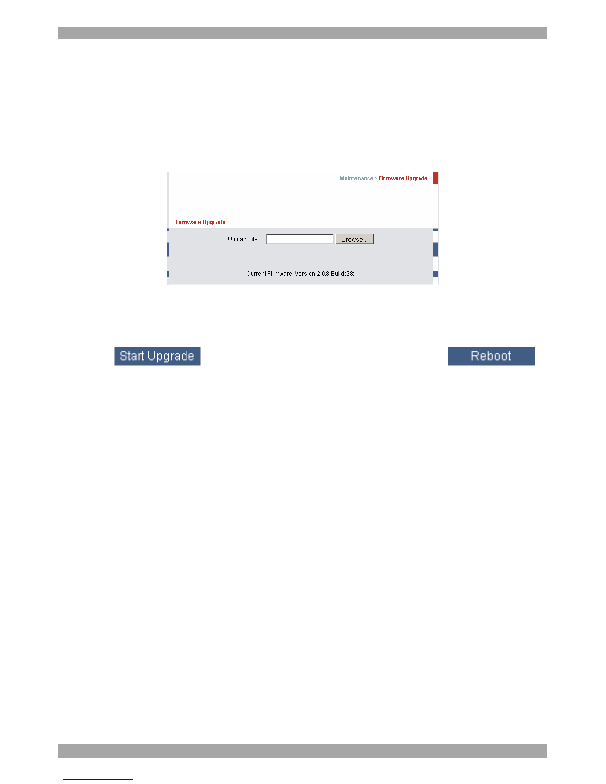
21. Maintenance > Firmware Upgrade
Upgrade the Smart IP Access firmware to take advantage of new features. You can
receive firmware updates by email or download them from the Minicom Web site.
Save the firmware file on the Client computer.
From the menu select Firmware Upgrade. The Firmware Upgrade page appears
see Figure 16.
Figure 16 Firmware Upgrade page
1. Locate and install the firmware file.
2. Click . The upgrade starts. On completion, click .
The unit reboots. After about 30 seconds the Login page appears.
Notes
(a) When KVM.net is enabled (in the Configuration page see page 12), all
firmware upgrades are done via KVM.net.
(b) Depending on the type of firmware upgrade, the following settings may be
erased: User settings, KVM switch settings, mouse and video adjustments and
RS232 settings. For more information refer to the firmware release notes. The
network settings remain intact.
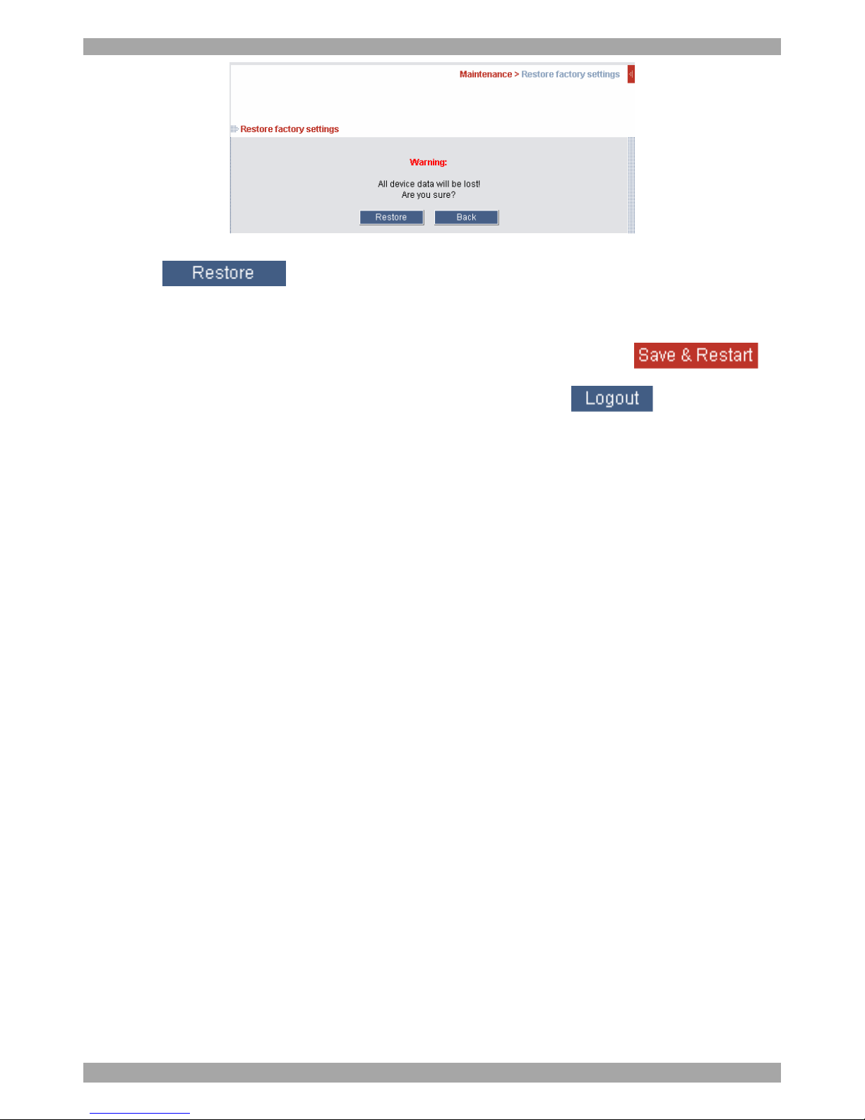
22. Maintenance > Restore Factory Settings
You can restore the Smart IP Access system to the factory settings. This restores
the original Smart IP Access parameters, resetting all the information added by the
administrators, including: Network settings, Servers, Switches, Users, Passwords
etc.
Warning! Once reset the data cannot be retrieved.
To restore factory settings:
1. From the menu select Restore Factory Settings. Restore Factory Settings
appears see Figure 17.
Page 22
SMART IP ACCESS
21
Figure 17 Restore factory settings
2. Click
23. Saving changes and logging out
To save any configuration changes and restart the IP Access click .
To exit the configuration menu and close the session click .
Only one Administrator can log into the configuration area at a time. An idle
timeout of 30 minutes terminates the session.
24. Starting a remote session
At a Client computer open Internet Explorer (6.0 and above) and type the Smart IP
Access’s IP address. https://IP address. The Login box appears. Type your
username and password and press Enter. By default, the user name is: admin and
the password is access, (both lower case).
On first connection install the Minicom certificate and ActiveX control.
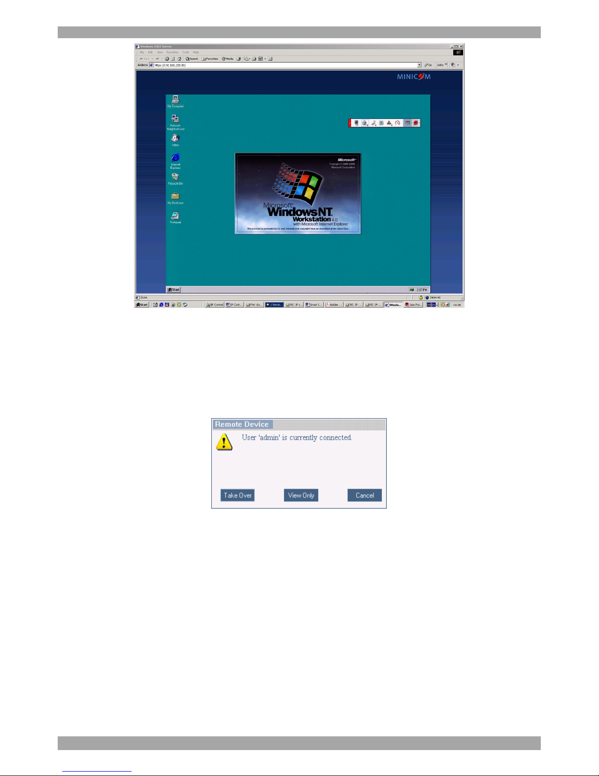
The screen of the Target Server connected directly to Smart IP Access, or the
currently selected server on the KVM switch with Smart IP Access toolbar appears
see Figure 18.
Page 23
USER GUIDE
22
Figure 18 Remote session window
24.1 Taking over a busy remote session
When connecting to a busy Target Server an Administrator has the option to take
over the Target Server. A User only has this option when the current session is run
by another User, but not by an Administrator. The following message appears
Figure 19 Busy remote session options
Choose to take over or view only or cancel.
24.2 Full screen mode
Work on the Target Server as if you are working on a local computer, with full
screen mode.
To work in full screen mode:
1. Ensure that the Client computer has the same screen resolution as the Target
Server.
2. Press F11. The Internet Explorer window disappears, leaving the Internet
Explorer menu bar at the top.
Page 24
SMART IP ACCESS
23
3. Right click the Internet Explorer menu bar and check Auto-Hide. The Internet
Explorer menu bar disappears. You are in full screen mode.
To exit full screen mode:
Press F11. Or place the mouse at the top of the window to display the Internet
Explorer toolbar and click the Restore button.
Note! Full screen mode can also be activated from the Toolbar menu, see page 31.
24.3 Moving or hiding the Toolbar
The Toolbar can be dragged and dropped to anywhere on the screen, by clicking
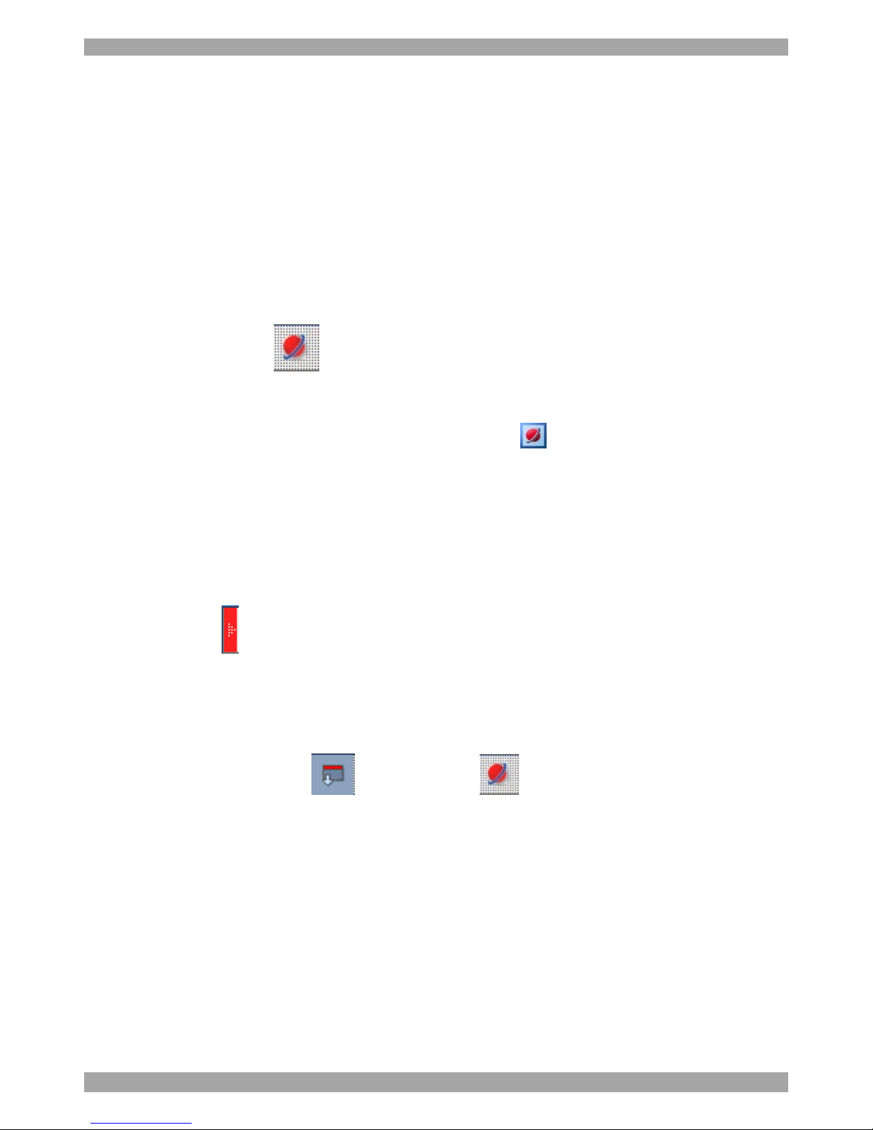
and dragging the logo .
To hide the Toolbar, either:
Double-click the Smart IP Access System tray Icon .
Or
Press F9.
To display the Toolbar repeat the above actions. See also page 31.
To minimize the Toolbar:
Click the arrow . Click again to maximize the Toolbar.
24.4 Switching to a different server/device
To connect to a different server/device:
1. From the Toolbar, click , or right-click . A list of connected
servers/devices appears.
2. Click the desired server or Serial device. The screen of the server or the Serial
device window appears.
Page 25
USER GUIDE
24
24.5 Changing the performance settings
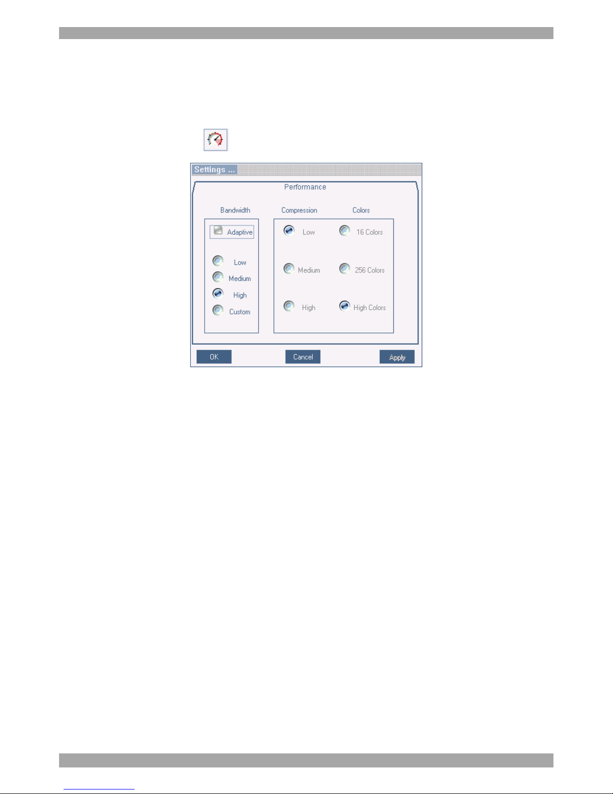
You can alter the bandwidth settings from the Toolbar.
To alter the settings:
From the Toolbar, click . The Settings.. box appears, see Figure 20.
Figure 20 Settings.. box
Bandwidth
Choose from the following options
Adaptive – automatically adapts to the best compression and colors.
Low - Select Low for high compression and 16 colors.
Medium - Select medium for medium compression and 256 colors. Medium is
recommended when using a standard internet connection.
High - For optimal performance when working on a LAN, select High. This gives
a low compression and high colors (16bit).
Custom – You cam choose your own compression and color levels.
Click OK. The screen of the last accessed Target Server appears.
Page 26
SMART IP ACCESS
25
24.6 Adjusting the Video settings
To change the video settings:
From the Toolbar, click . You have the following options:
· Refresh
· Manual Video Adjust
· Auto Video Adjust
Each option is explained below.
24.6.1 Refresh
Select Refresh or press Ctrl+R to refresh the Video image. Refresh may be needed
when changing the display attributes of a Target Server.
24.6.2 Manual Video Adjust
Use the manual video adjustment for fine-tuning the Target Server video settings
after auto adjustment or for adapting to a noisy environment or a non-standard
VGA signal or when in full-screen DOS/CLI mode.
To adjust the video manually:
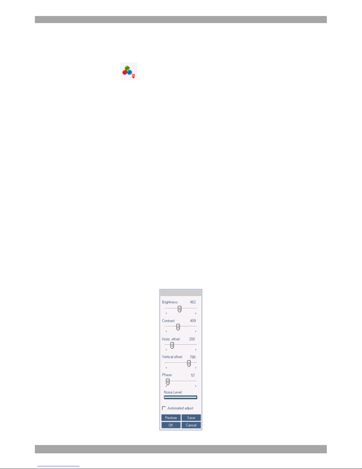
1. Click Manual Video Adjust. A slider bar appears. See Figure 21. Also a red
frame appears around the screen. This represents the screen area according to
the Server's screen resolution. Perform the adjustments inside and relative to
this frame.
Figure 21 Manual Video Adjustments controls
Page 27

USER GUIDE
26
2. Move the sliders to change the displayed image. Click in the area of the sliders
for fine-tuning.
Brightness / Contrast - use the scales to adjust the brightness and contrast of the
displayed image.
Horizontal Offset - defines the starting position of each line on the displayed
image.
Vertical Offset - defines the vertical starting position of the displayed image.
Phase - defines the point at which each pixel is sampled.
Noise Level - represents the Video "noise" when a static screen is displayed.
Automated adjust – When checked, the video adjusts automatically whenever
there is a change in the screen resolution.
24.6.3 Auto Video Adjust
To adjust the video automatically:
We recommend opening Windows Explorer (or similar) in the background.
Click Auto Video Adjust. The process takes a few seconds. If the process runs for
more than 3 times, there is an abnormal noise level. Check the video cable and
verify that no dynamic video application is running on the Target Server’s desktop.
Perform the procedure where necessary for each Target Server or new screen
resolution.
24.7 Power cycle
Power cycle button . This option is currently unavailable.
24.8 Keyboard key sequences
Click . A list of defined keyboard sequences appears. When clicked, these
transmit directly to the Target Server, and will not affect the Client computer.
For example, select Ctrl-Alt-Del to send this three key sequence to the Target
Server to initiate its Shutdown/Login process.
To add a keyboard sequence:
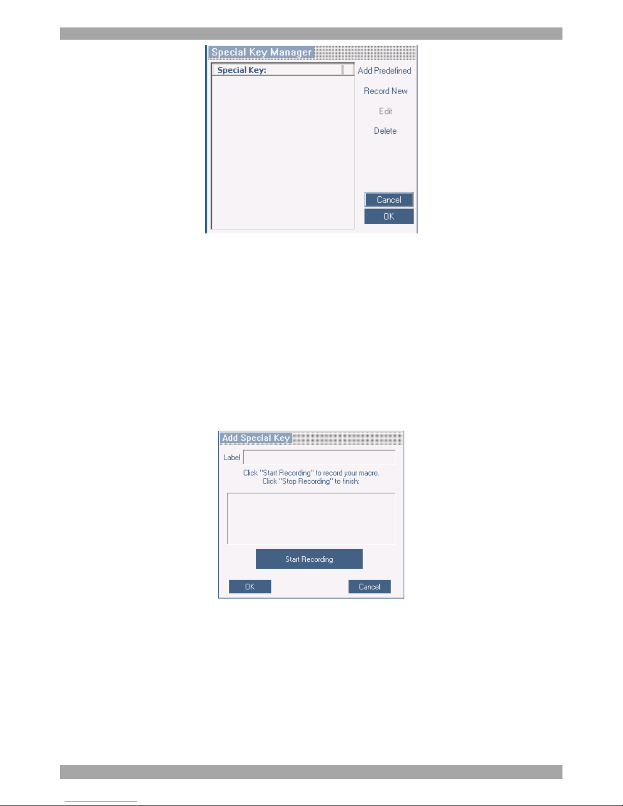
Click Add/Remove. The Special Key Manager box appears see Figure 22.
Page 28
SMART IP ACCESS
27
Figure 22 Special Key Manager box
To add a predefined sequence:
1. Click Add Predefined. A list of sequences appears.
2. Select the desired sequence and click OK. The sequence appears in the Special
Key Manager box.
3. Click OK. The sequence appears in the Keyboard Key sequence list.
To record a key sequence:
1. From the Special Key Manager box press Record New. The Add Special Key
box appears see Figure 19.
Figure 23 Add Special Key box
2. Give the key sequence a name in the Label box.
3. Click Start Recording.
4. Press the desired keys. The keys appear in the area provided.
5. Click Stop Recording.
6. Click OK.
Page 29
USER GUIDE
28
To edit a key sequence:
1. From the Special Key Manager box select the desired key.
2. Click Edit.
3. Click Start Recording
4. Press the desired keys. The keys appear in the area provided.
5. Click Stop Recording.
6. Click OK.
24.9 Synchronizing mouse pointers
When working at the Client computer, two mouse pointers appear: The Client
computer’s is on top of the Target Server’s. The mouse pointers should be
synchronized. The following explains what to do if they are not synchronized.
Warning
Before synchronizing mouse pointers adjust the video of the Target Server,
(explained above) otherwise mouse synchronization may not work..
24.9.1 Aligning the mice pointers
When accessing the Target Server, the mice may appear at a distance to each other.
To align the mouse pointers:
From the Toolbar click / Align or press Ctrl+M simultaneously. The mice
align.
24.9.2 Calibrating mice pointers
A Target Server may have a different mouse pointer speed to the Client computer.
Calibrating automatically discovers the mouse speed of the Target Server and
aligns the two pointers.
To perform the calibration when the Target Server Operating system is, Windows
NT4, 2000 or 98:
From the Toolbar click / Calibrate. Smart IP Access saves this alignment so
calibration is only needed once per Target Server.
If the Video Noise Level is above zero, calibration may not work. Go to Video
Adjustment and try to eliminate the noise by pressing Auto video adjust and/or
adjusting the bars in Manual video adjust, then perform the mouse calibration.
Page 30
SMART IP ACCESS
29
Note! If the mouse settings on the Target Server were ever changed, you must
synchronize mouse pointers manually, as explained below.
24.9.3 Manual mice synchronization
If the mouse settings on the Target Server were ever changed, or when the
Operating system on the Target Server is, Windows XP / 2003 Server / Vista,
Linux, Novell, SCO UNIX or SUN Solaris you must synchronize the mouse
pointers manually.
To manually synchronize mouse pointers:
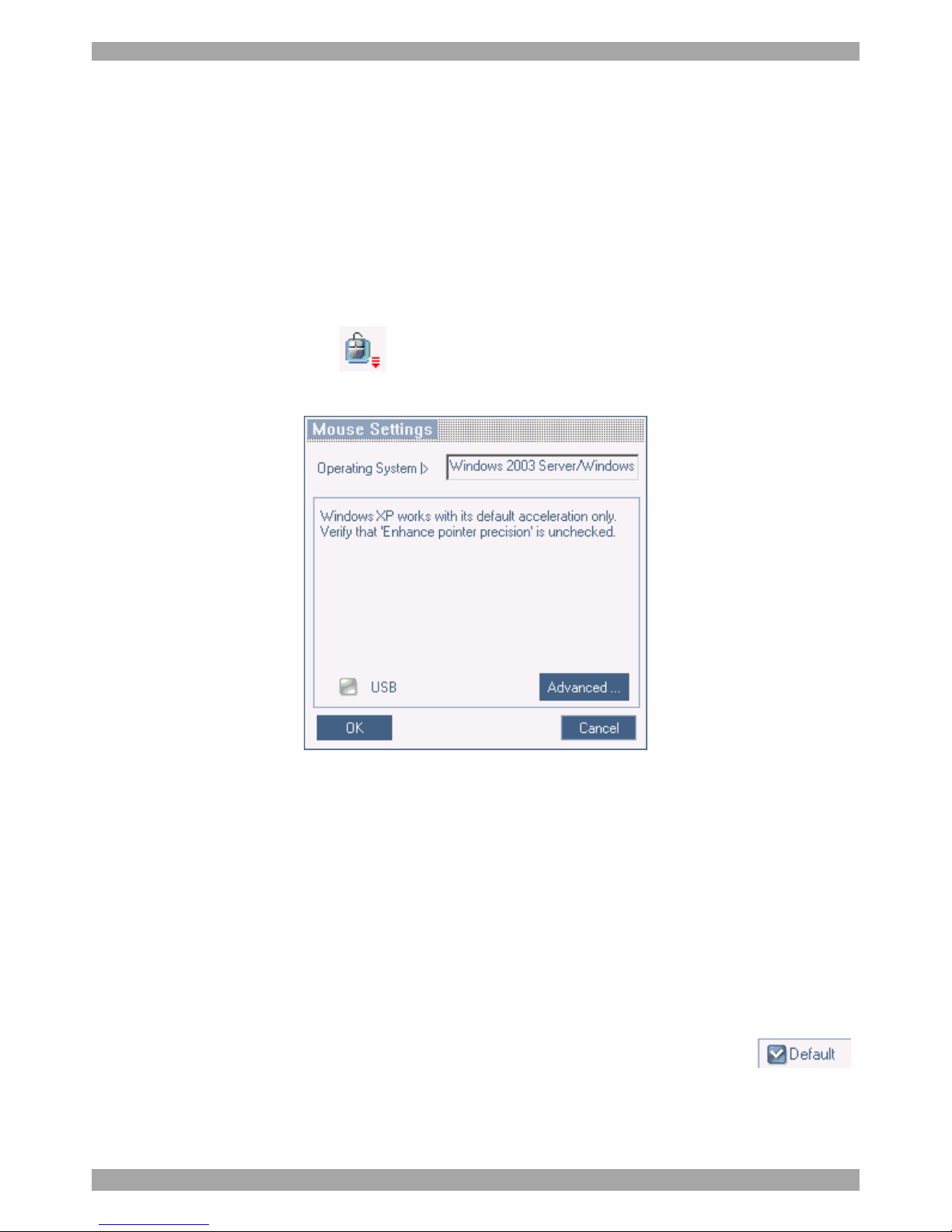
1. From the Toolbar click / Manual Settings. The Mouse Settings box
appears see Figure 24.
Figure 24 Mouse Settings box
2. Select the Target Server’s Operating System and click OK. Instructions and
sliders appear.
3. Follow the instructions and set any relevant sliders to the same values as set in
the Target Server’s Mouse Properties window.
2 examples!
For Windows XP, go to the Mouse settings on the Target Server and uncheck
Enhance pointer precision.
For Windows NT4. If Mouse Properties were ever changed for the Target Server –
even if they have been returned to their original state - uncheck default - .
Click OK. The mouse pointers should be synchronized.
Page 31
USER GUIDE
30
USB
The USB option in Mouse Settings box is available for RICC and X-RICC USB
and Phantom Specter USB and for unsupported operating systems and SUN
Solaris. Use this option if you are sure of the custom acceleration algorithm you are
using, or have been informed so by customer support.
Advanced – Mouse Emulation
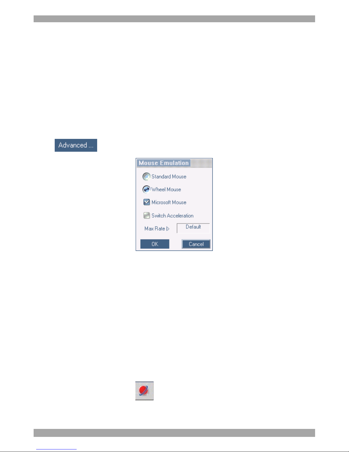
In the Advanced Mouse settings, you can set the type of mouse that you would like
Smart IP Access to emulate. We recommend not changing the advanced settings
unless there is erratic mouse behavior (the mouse is making random clicks and
jumping arbitrarily around the screen).
Click the Mouse Emulation box appears see Figure 25.
Figure 25 Mouse Emulation box
Select the mouse connected to the Local Console port on the Smart IP Access, e.g.
if the local mouse is a non-Microsoft 2 button mouse, select Standard Mouse and
uncheck Microsoft Mouse.
Switch Acceleration - In some KVM switch brands (for example G&D, Rittal),
the switch accelerates the mouse on top of the acceleration provided by the
operating system. If necessary, check this option to compensate (decelerate) the
switch acceleration and achieve full synchronization.
Max Rate - this defines the maximum mouse report rate. For Sun Solaris the
default value is 20 in order to support older Sun versions.
24.10 Minicom logo menu features
Right click the Minicom logo , a menu appears. From this menu you can
access the connected devices. You also have the following features:
Disconnect – You can disconnect the session by clicking Disconnect.
Page 32
SMART IP ACCESS
31
About - Click About to verify the Client, Firmware, KME (Keyboard/Mouse
Emulation firmware) and Switch file versions installed on your Smart IP Access.
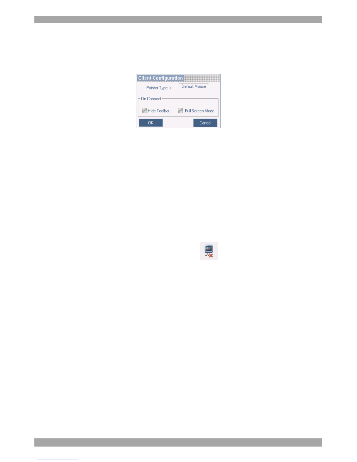
Local Settings – Click Local settings, the Client Configuration box appears, see
Figure 26
Figure 26 Client Configuration box
Pointer type – From the Drop-down menu you can change the Client computer
mouse pointer to appear as a dot or to not appear at all.
Hide Toolbar – Check this option to hide the Toolbar from the next reconnection
onwards. To toggle the Toolbar on and off, press F9. See above page 23.
Full Screen Mode - Check this option to make the remote session screen appear in
full screen mode from the next reconnection onwards. To toggle the full screen
mode on and off, press F11.
24.11 Disconnecting the remote session
To disconnect the session, on the Toolbar, click . The Login box appears. You
can re-login or close the browser window.
25. Troubleshooting - Restoring factory defaults
Section 22 on page 20 explained how to restore factory settings from the Web
interface. When you cannot access the system e.g. you have forgotten the
Username or Password, you can restore factory defaults from the Smart IP Access
unit.
To restore factory defaults:
1. Switch on the unit.
2. Within 3 seconds of switching on, press and keep holding down the Local
button.
3. Press and release the Reset button. The Remote LED illuminates.
4. While the Remote LED illuminates, release the Local Button then re-press it
and immediately release it. The Remote LED turns off.
Page 33
USER GUIDE
32
5. Wait 2 minutes until the unit finishes booting.
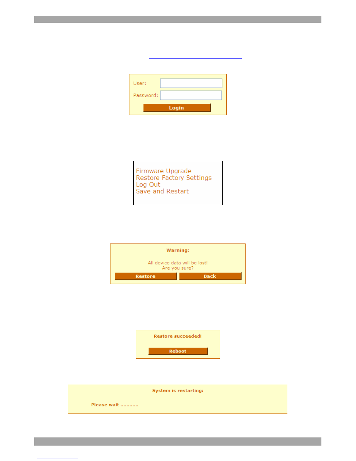
6. Connect the lower network interface (LAN 2) to the network, and login with the
default IP address of the unit: http://192.168.0.155/config. The Login box
appears see Figure 27.
Figure 27 Login box
7. Type username: admin , password: SAFEmode. (Case sensitive). This
username and password works only after the reset procedure described above. A
menu appears, see Figure 28.
Figure 28 Menu
8. From the menu choose Restore Factory Settings. A warning appears see
Figure 29.
Figure 29 Restore factory settings
9. Click Restore. The factory defaults are restored and all user data, switch
configurations, user names and passwords are erased. When the process finishes
Figure 30 appears.
Figure 30 Reboot
10. Click Reboot to restart the unit. The following message appears.
Figure 31 System restarting
Page 34

SMART IP ACCESS
33
11. Wait for 2 minutes and then type the default configuration IP address of the
unit: https://192.168.0.155/config into your web browser. The Login page
appears as in Figure 6 on page 10.
12. Type the default Administrator user name and password. Username: admin,
password: access. (Case sensitive).
13. Configure the unit according to your network settings, see page 11. Create new
users and change the Administrator’s password in the User Settings, see page
14.
Page 35

USER GUIDE
34
26. Technical Specifications
Operating systems
Target Server
Windows 3.1, 9X, 2000, XP, NT4, 2003 Server,
Vista. DOS, Novell 3.12 – 6, Linux
Client Computer
Windows NT4.0, 2000, XP or 2003 Server, with IE
6.0 or higher
Resolution
Target Server
Up to 1600x1200 @85Hz
Client Computer
Recommended - resolution should be higher than on
Target Server
Video and mouse synchronization Both auto and manual modes
Connections
Ethernet – 2 X RJ45 – 10/100 Mbit/sec autosensing
Serial – 2 X RJ45
Local KVM connection – Screen HDD15,
Keyboard./Mouse – MiniDIN6
Computer / switch connection – Screen HDD15,
Keyboard./Mouse – MiniDIN6 3 in 1 cable 1.8m
Weight
1.204kg/ 2.65lbs
Dimensions (H x D x W)
44 X 230 X 215mm / 1.7 x 9 x 8.5in
Power supply
100-240 VAC, 50/60 Hz, 0.24 A
Operating temperature
0°C to 40°C / 32° to 104°F
Storage temperature
-40°C to 70°C/-40°F to 158°F
Humidity
80% non condensing relative humidity
Page 36

SMART IP ACCESS
35
27. Video Resolution and Refresh Rates
Hz →
56 60 65 66 70 72 73 75 76 85 86
640x480 x x x x x x
720x400 x x
800x600 x x x x x x
1024x768 x x x x x x x
1152x864 x
1152x900 x x
1280x720 x
1280x768 x x
1280x960 x x
1280x1024
x x x x x
1600x1200
x x x x x
28. Safety
The device must only be opened by an authorized Minicom technician. Disconnect
device from AC mains before service operation!
Caution
Risk of explosion if battery is replaced by an incorrect type. Dispose of used
batteries according to the instructions.
29. User Guide Feedback
Your feedback is very important to help us improve our documentation. Please
email any comments to: [email protected]
Please include the following information: Guide name, part number and version
number (as appears on the front cover).
Page 37

USER GUIDE
36
30. WEEE Compliance
WEEE Information for Minicom Customers and Recyclers
Under the Waste Electrical and Electronic Equipment (WEEE) Directive and implementing
regulations, when customers buy new electrical and electronic equipment from Minicom they
are entitled to:
· Send old equipment for recycling on a one-for-one, like-for-like basis (this varies
depending on the country)
· Send the new equipment back for recycling when this ultimately becomes waste
Instructions to both customers and recyclers/treatment facilities wishing to obtain
disassembly information are provided on our website www.minicom.com.
Page 38

SMART IP ACCESS
37
Regional Offices
Germany
Kiel
Tel: + 49 431 668 7933
France
Vincennes
Tel: + 33 1 49 57 00 00
Italy
Rome
Tel: + 39 06 8209 7902
England
Camberley
Tel: + 44 (0) 1276 25053
www.minicom.com
 Loading...