

Page 1
International HQ
Jerusalem, Israel
Tel: + 972 2 535 9666
North American HQ
Linden, New Jersey
Tel: + 1 908 486 2100
European HQ
Zurich, Switzerland
Tel: + 41 1 455 6220
Italy
Rome
Tel: + 39 06 8209 7902
www.minicom.com Customer support - [email protected]
Supervisor Smart 4-port
User Guide
Page 2

Table of Contents
Introduction...........................................................................................2
The Supervisor Smart 4-Port...............................................................2
Features of the Smart 4........................................................................3
Installing the Smart 4 system..............................................................5
Connecting cables to the Smart 4 front panel ...................................5
Connecting cables to the Smart 4 rear panel.....................................6
Operating the Smart 4 ..........................................................................8
Switching between computers............................................................8
Scanning computers ............................................................................9
The Settings mode ...............................................................................9
Setting the scan time period .............................................................10
Changing the hotkey ..........................................................................10
Resetting the Smart 4.........................................................................10
Making advanced adjustments..........................................................11
Replacing a computer ........................................................................11
Keyboard settings when replacing a computer...............................11
Mouse settings when replacing a computer ....................................12
Viewing the settings...........................................................................13
Exiting the Settings mode .................................................................13
Technical Specifications....................................................................15
1
Page 3

Introduction
Minicom Advanced Systems Ltd (Minicom) is a leading
manufacturer of KVM switches for multiple server control.
Minicom also manufactures interactive systems for Computer
Equipped Learning Environments. It is also the world leader
in the development and deployment of cutting edge CAT5
technology.
The Supervisor Smart 4-Port
The Supervisor Smart 4-Port (Smart 4) from Minicom is a
Keyboard Video Mouse (KVM) switch. With the Smart 4 you
can access, monitor and control four computers from one
KVM console.
To use the Supervisor Smart 4-Port unit, you need 1 high
resolution CPU cable for each connected computer.
The following accessories are available and must be ordered
separately:
• Rack mounting set P/N 5AC20201
• Desk mounting set P/N 5AC20200
• Power supply P/N 5PS20025
2
Page 4

Features of the Smart 4
• Pure hardware Plug and Play
• Ideal solution for small and home office (SOHO)
environments
• Scan function
• High video resolution
• Can be operated from the Smart 4’s front panel or a
keyboard hotkey
• Eliminates excess equipment
• Full keyboard and mouse emulation for connected
computers
• Microsoft Intellimouse and Wheel mouse support
• The connected computers can have different operating
systems
• Separate Desk and Rack mounting kits
• Optional power supply for cascading, otherwise no
external power supply is necessary!
3
Page 5
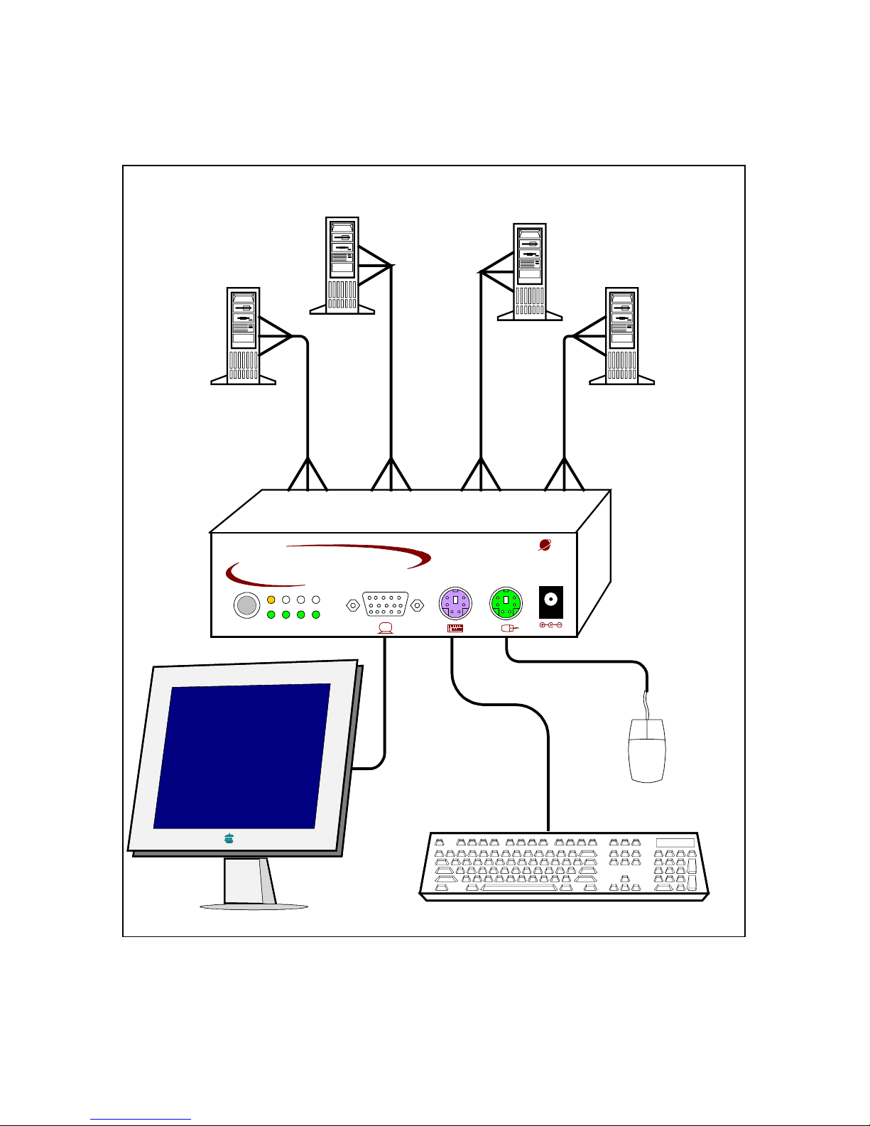
Figure 1 illustrates the basic configuration of the Smart 4
System.
Computer 1
Smart 4
Computer 2
Computer 3
Computer 4
1
Supervisor
SMART
Select 2 3 4
6VDC
MINICOM
Figure 1 The Smart 4 configuration
4
Page 6

Installing the Smart 4 system
Before installing the system do the following:
• Switch off all computers.
• Place cables away from fluorescent lights, air
conditioners, and machines that are likely to generate
electrical noise.
Connecting cables to the Smart 4 front panel
Connect a keyboard, screen and mouse to the front panel
using their existing cables.
An optional Power adapter when used is also connected to the
front panel.
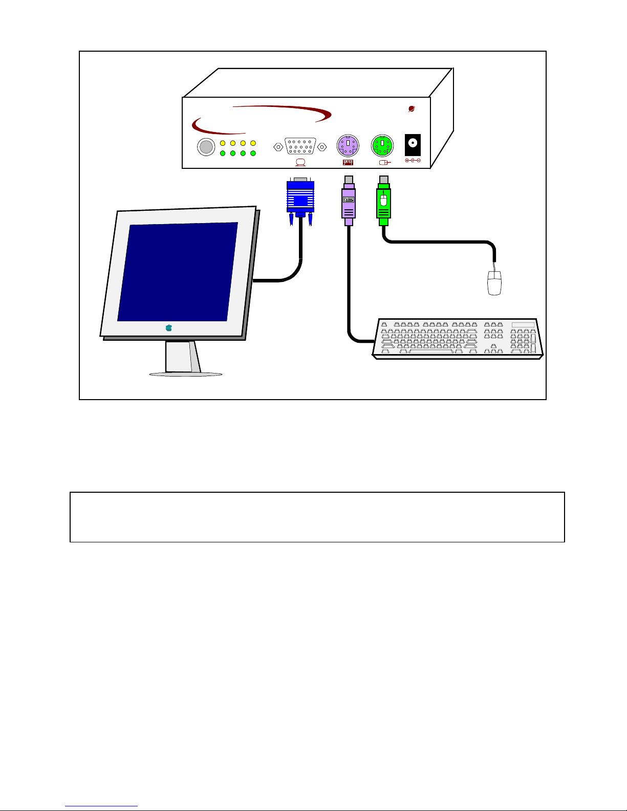
Figure 2 illustrates the front panel connections. The panel
contains 2 LED banks. The top LED bank shows which
computers are connected and powered on. The bottom LED
bank shows which computer is currently selected.
5
Page 7
Smart 4
front panel
1
Supervisor
SMART
Select
234
6VDC
MINICO M
Figure 2 The Smart 4 front panel connections
Connecting cables to the Smart 4 rear panel
Important! Always connect the front panel connections
before the rear panel connections.
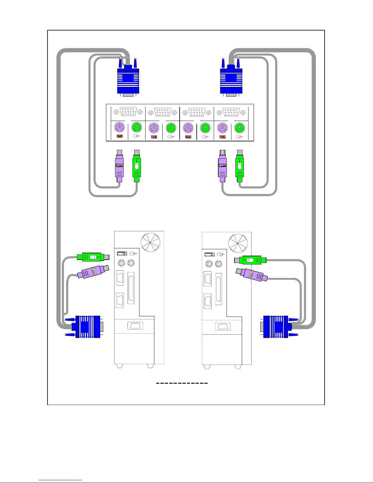
Connect the CPU cables to the Smart 4 rear panel, and to the
computers. Figure 3 illustrates the CPU cables connected to
the Smart 4 and computers 1 and 4. The connections are the
same for computers 2 and 3.
6
Page 8
To computer's
Keyboard port
To computer's
Mouse port
To
computer's
Video port
Computer 1
CPU cable
www.minicom.c om
1234
To computer's
Keyboard port
To computer's
Mouse port
To
computer's
Video port
Computer 4
CPU cable
Smart 4
rear panel
Figure 3 The Smart 4 rear panel connections
7
Page 9

Operating the Smart 4
To prepare the system for operation:
1. Connect the cables to the front panel.
2. Connect the cables to the back panel.
3. Switch on the computers.
Switching between computers
There are two ways to switch between computers.
1. On the front panel of the Smart 4, press the button to
switch to the next computer.
2. On the keyboard:
To switch to the next computer forwards press Shift
then, +. Release Shift, before pressing +.
To switch to the next computer backwards press Shift
then, -. Release Shift, before pressing -.
Note! With a US English keyboard you can use the + key of
the alphanumeric section or of the numeric keypad. With a
Non-US English keyboard only use the + key of the numeric
keypad.
When switching computers the illuminated LED of the
bottom bank indicates which computer is currently selected.
8
Page 10

Scanning computers
The Smart 4 can scan the connected computers at intervals of
between 1 and 99 seconds. The default time period is 0
seconds (disabled) – change this in the Settings mode see the
paragraph below. During scanning you cannot work on the
computers.
To scan computers:
Press the hotkey Shift then, S. Release Shift before pressing
S. The scan activates.
To end scanning:
Press Esc.
The Settings mode
Enter the Settings mode to:
• Set the scan time interval
• Change the hotkey
• Make advanced adjustments
• View settings
To enter the Settings mode:
Press Shift then, Tab. Release Shift before pressing Tab. All
3 keyboard LEDs glow when in the Settings mode.
9
Page 11

Setting the scan time period
To set the scan time period:
Press T followed by a 2-digit time period of between 01-99
seconds. The 3 keyboard LEDs blink and the new setting is
now functional.
Changing the hotkey
You can change the hotkey from Shift to Alt or Ctrl. Once
changed, all references in this Guide to Shift now refer to the
new hotkey.
To change the hotkey:
To Type the letters
Alt HA
Ctrl HC
Shift HS
Resetting the Smart 4
To reset the Smart 4:
Press and hold the Switching button for more than 5 seconds.
Release the Switching button after your monitor blinks once.
10
Page 12

Making advanced adjustments
The Smart 4 operates with:
• Windows, Linux, HP UX, Alpha UNIX or SGI systems
• 2 or 3 button PS/2 mouse, Intellimouse, Wheel mouse or
5-button mouse
Replacing a computer
When a computer is replaced with a different computer type
while the Smart 4 is in use, we recommend turning the new
computer off before connecting it to the Smart 4.
When turning the computers off is inconvenient, do the
following:
In the Settings mode adjust the keyboard and mouse to be
compatible with the new computer. See the tables below.
Keyboard settings when replacing a computer
For Type the letters
PC (Windows, Linux) PC
HP UX U1
Alpha UNIX, SGI U2
11
Page 13

Set keyboard settings to:
• PC when operating Intel based computers.
• U1 when operating HP UX computer.
• U2 when operating Alpha UNIX, SGI or Open VMS
computers.
Mouse settings when replacing a computer
For Type the letters
5-button mouse EP
Wheel mouse, 5-button mouse or
Intellimouse
IN
2 or 3-button mouse PS
Set mouse settings to EP when operating computers with
Operating Systems that support wheel mouse functionality:
(Windows XP).
Set mouse settings to IN when operating computers with
Operating Systems that support wheel mouse functionality:
(Windows – 98, ME, 2000, XP or Linux).
Set mouse settings to PS when operating computers with
Operating Systems that don’t support wheel mouse
functionality: (Windows 95, NT4, DOS, Linux, UNIX or
Novell).
12
Page 14

Viewing the settings
View the settings and firmware revision in any text editor.
To view the settings:
1. Before entering to the Settings mode switch your
keyboard layout to English.
2. Open any text editor, e.g. Notepad.
3. Press Shift, Tab to enter the Settings mode.
4. Press F. The settings appear in the text editor.
Exiting the Settings mode
To save changes and exit the Settings mode:
Press Esc.
13
Page 15

A summary of the Settings mode operations
The table below sets out the Settings mode operations.
Operation Press
Enter Settings mode Shift, Tab
Exit and save changes Esc
Set the scan time period T, xx (00-99)
Change Hotkey to Alt HA
Change Hotkey to Ctrl HC
Change Hotkey to Shift HS
Mouse setting - 5-button mouse EP
Mouse setting - Wheel mouse or IN
Mouse setting – two-button mouse PS
Keyboard setting – PC PC
Keyboard setting –HP UX U1
Keyboard setting –Alpha UNIX U2
View Status Report F
Intellimouse
14
Page 16

15
Technical Specifications
Resolution
Up to 1920 x 1440@75 Hz
Video Signal
Analog Signal: Red Green Blue 0.7Vp-p /
75Ω positive, HD15
Video Sync
TTL Compatible positive/negative
Keyboard
PS/2 type, MiniDIN6
Mouse
Microsoft Intellimouse, Wheel mouse,
PS/2 type mouse, 5-button mouse.
MiniDIN6
Computer types
Intel, Alpha compatible
Platforms
IBM Compatible, PS/2 (SUN with
external adapter)
Operating Systems
Windows - 3.1, 9x, 2000, ME, XP, NT4,
SGI, Novell, DOS, Linux, HP UX, Alpha
UNIX, Open VMS, True64, QNX,
FreeBSD, BeOS.
Dimensions
170 x 90.5 x 40.5 mm
Weight
580g
Power consumption
120mA
Power supply
(optional)
6V 2A
Operating
temperature
00C to 400C / 32ºF to 104ºF
Storage temperature
- 40
0
C to 700C / -40ºF to 158ºF
Humidity
80% non condensing relative humidity
 Loading...