

Page 1
PX Serial - Quick Start Guide
1. Introduction
To take advantage of the full range of features, we recommend you read the softcopy
User Guide after performing the Quick Start procedure. It’s in PDF format on the
supplied CD or on our website www.minicom.com in the Support section.
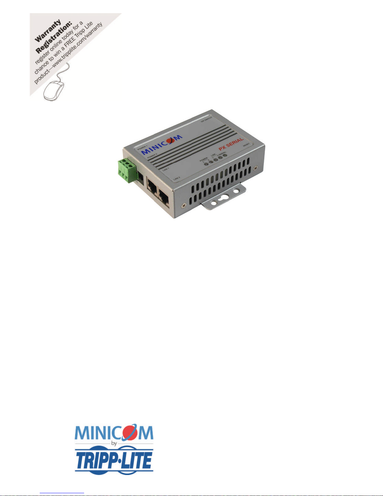
PX Serial is a one-port RS232/422/485 to Redundant Ethernet device server. PX
Serial can be configured by a web browser in https, or SSH console. Additional
management features include SNMP support and email alerts.
2. The PX Serial components
The package includes:
1 PX Serial unit
1 Power adapter (100-240VAC)
Mounting kit foot pads
Minicom CD
1111 W. 35th Street, Chicago, IL 60609 USA
www.tripplite.com/support
Copyright ©2012 Tripp Lite. All rights reserved.
Page 2
PX SERIAL
1
3. PX Serial ports
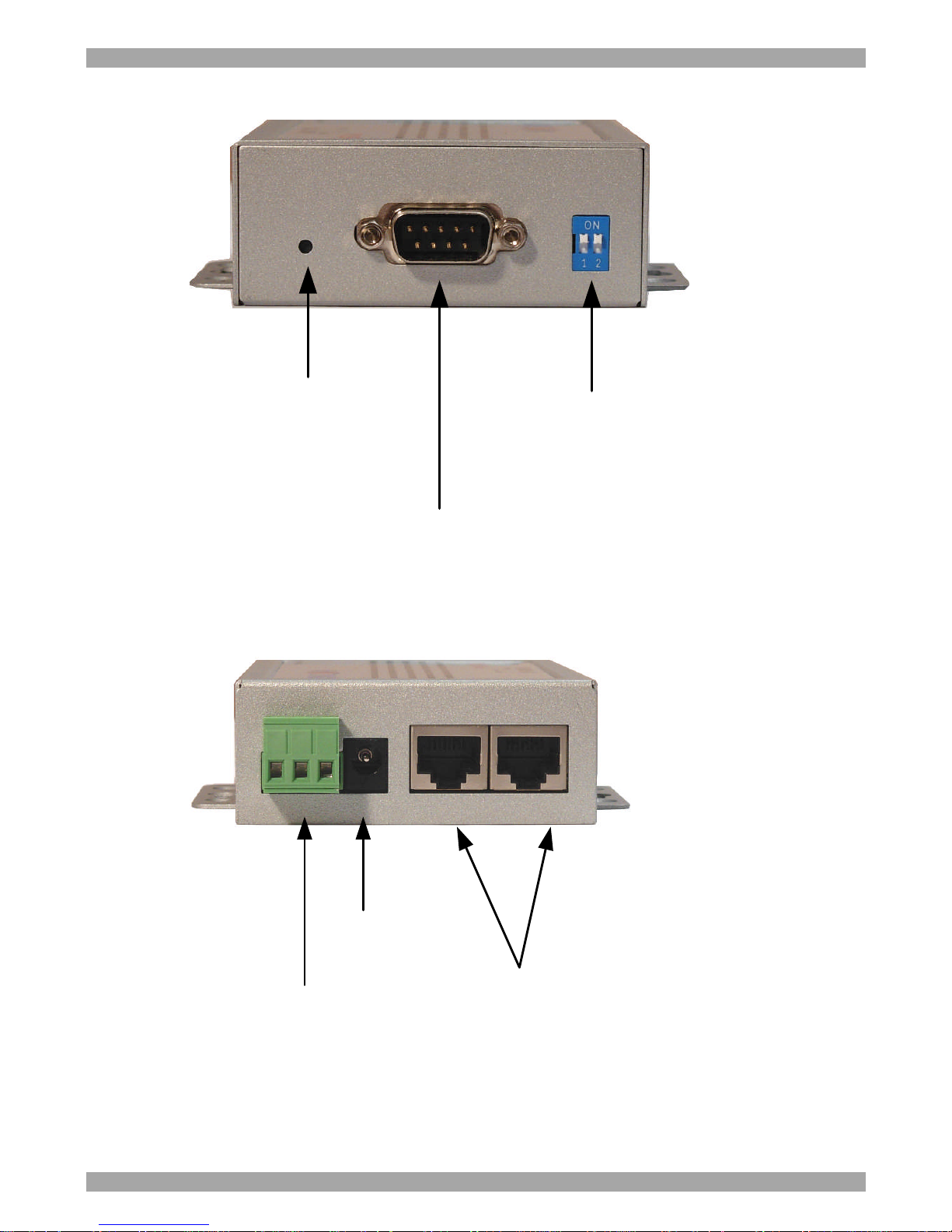
Hardware reset button
RS232/422/482 port, DB9M 15KV
ESD for all signals Speed:110 bps
to 460.8kbps
Long distance RS422 /485
120 Ohm termination
dipswitches
Figure 1 PX Serial ports side
Redundant Dual 10/100M Ethernet
Auto MDI/MDIX AutoRecovery<200ms Built-in 1.5KV
magnetic isolation
9-30 VDC Power
Jack
12-48 VDC Terminal
Block
Figure 2 PX Serial ports side 2
Page 3

QUICK START GUIDE
2
4. PX Serial LEDs
LED Color Indication
PWR 1 Red On: Power 1 is on and booting up.
Blinking: Indicates an IP conflict, or DHCP or BOOTP server did not respond
properly.
Green On: Power is on and functioning normally.
Blinking: Located by Administrator’s Location function.
Off Power is off, or power error condition exists.
PWR 2 Red On: Power 2 is on and booting up.
Blinking: Indicates an IP conflict, or DHCP or BOOTP server did not respond
properly
Green On: Power 2 is on and functioning normally.
Blinking: Located by Administrator’s Location function.
Off Power is off, or power error condition exists.
Eth 1 Orange Blinking: 10 Mbps Ethernet connection.
Green Blinking: 100 Mbps Ethernet connection.
Off Ethernet cable is disconnected, or has a short.
Eth 2 Orange Blinking: 10 Mbps Ethernet connection.
Green Blinking: 100 Mbps Ethernet connection.
Off Ethernet cable is disconnected, or has a short.
Serial Orange Serial port is receiving data.
Green Serial port is transmitting data.
Off No data is being transmitted or received through the serial port.
5. Connecting the PX Serial
Connect the PX Serial to the power supply, the Network switch and Serial device as
explained below.
5.1 Connecting the Power supply
You can connect the PX Serial to the Power supply using the Terminal Block
(PWR1) and/or the Power Jack (PWR2). If both power inputs are connected, the PX
Serial is powered from the highest connected voltage. The PX Serial will only send a
loss of power alarm when power fails at both PWR1 and PWR2.
Page 4

PX SERIAL
3
5.1.1 Terminal Block (PWR1)
1. Insert the positive and negative wires of your DC supply into the V+ and Vcontacts of the terminal block connector – see below.
(GND / V- / V+)
2. Tighten the terminal screws to prevent the DC wires from coming loose – see
below.
Once connected to the power supply, Power 1 LED turns red to show unit booting
up. When the unit is ready and if the IP setting is running correctly, the LED turns
green.
5.1.2 Power Jack (PWR2)
Connect the supplied 12VDC power adapter, or 24VDC power input to the power
jack. Power 2 LED turns red to show unit booting up. When the unit is ready and if
the IP setting is running correctly the LED turns green.
5.2 Connecting to the network switch
Connect the PX Serial to the network switch via the LAN 1 or LAN 2 port using a
standard 10/100M Ethernet cable. The Ethernet interface supports auto MDI/MDIX.
The relevant LAN 1 or LAN 2 LED turns orange for 10M Ethernet or green for
100M Ethernet.
Both Ethernet ports 1 and 2 can be connected to different switches. If both ports are
connected when the device starts up then Ethernet port 1 is the master and Ethernet
port 2 is the backup. But if when the device starts up only Ethernet port 2 is
connected, then Ethernet port 2 remains the master port.
5.3 Connecting to the Serial device
Connect the Serial device to the DB9M port. The DB9M pin-out appears in the
softcopy User Guide.
Page 5
QUICK START GUIDE
4
5.4 Configuring the dipswitches
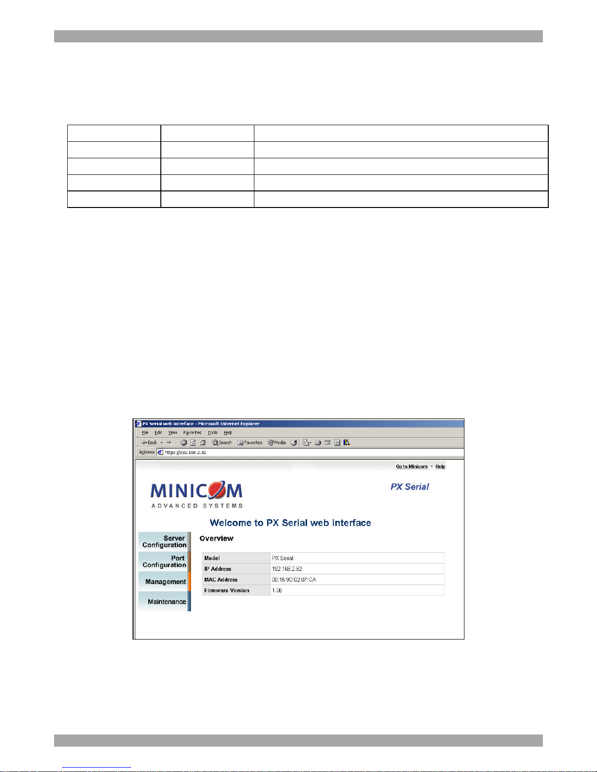
The Long-Range Termination dipswitches can configure 120 Ohm termination for
RS422 / 4-wire RS485 / 2-wire RS485. Set the dipswitches according to the
following table.
Dipswitch 1
Dipswitch 2
Configuration
ON ON 120 Ohm terminator for long distance 4-wire RS485 / RS422
ON OFF Don’t use this setting - it will cause errors!
OFF ON 120 Ohm termination for long distance 2-wire RS485
OFF OFF (Default) No termination for RS232/422/485 (short distance)
6. Configuring the PX Serial unit
The PX Serial unit can be managed by a Web interface, providing secure SSL
communication over the internet. The PX Serial comes with the default IP address
192.169.10.2 - this appears on the underside of the PX unit.
To display the Web interface:
1. Open your Web browser.
2. Type in the IP address of the PX Serial and press Enter. Note! The IP address
must begin with https:// and not http://. The web interface appears, see Figure 3.
Bookmark it for easy reference.
Figure 3 Overview page
The Overview page gives details of the current IP address, MAC address and
firmware version. The MAC address is also shown on the underside of the unit.
From the menu click Server Configuration to display a sub-menu.
Page 6
PX SERIAL
5
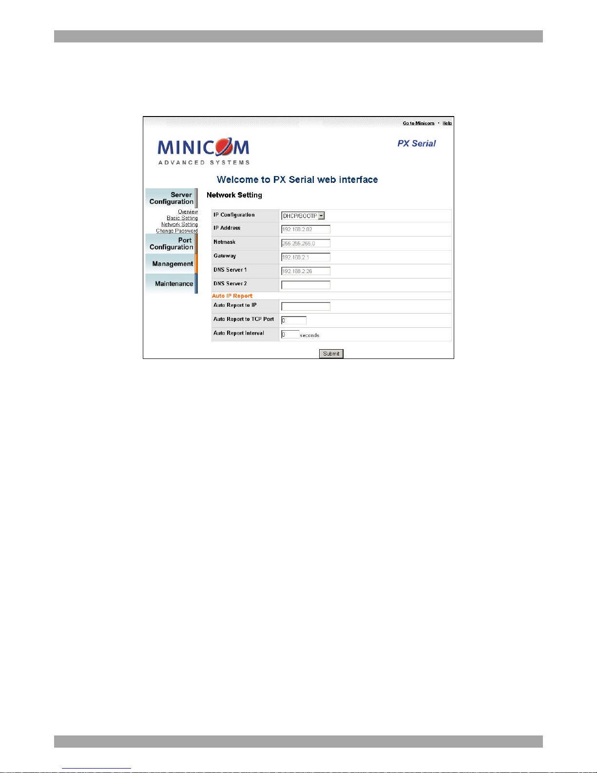
6.1 Network Setting
Consult your Network Administrator for the network settings.
Click Network Setting, the following appears.
Figure 4 Network Setting
On this page you configure for the PX:
IP Configuration – DHCP or static
IP address
Netmask
Gateway
DNS servers
For dynamic IP address reporting at defined time intervals, fill in the Auto IP report
fields.
7. Port Configuration
Port Configuration covers Serial Parameter settings, such as baud rate, data bits, stop
bits, parity, and flow control.
From the menu click Port Configuration to display a sub-menu.
Page 7
QUICK START GUIDE
6
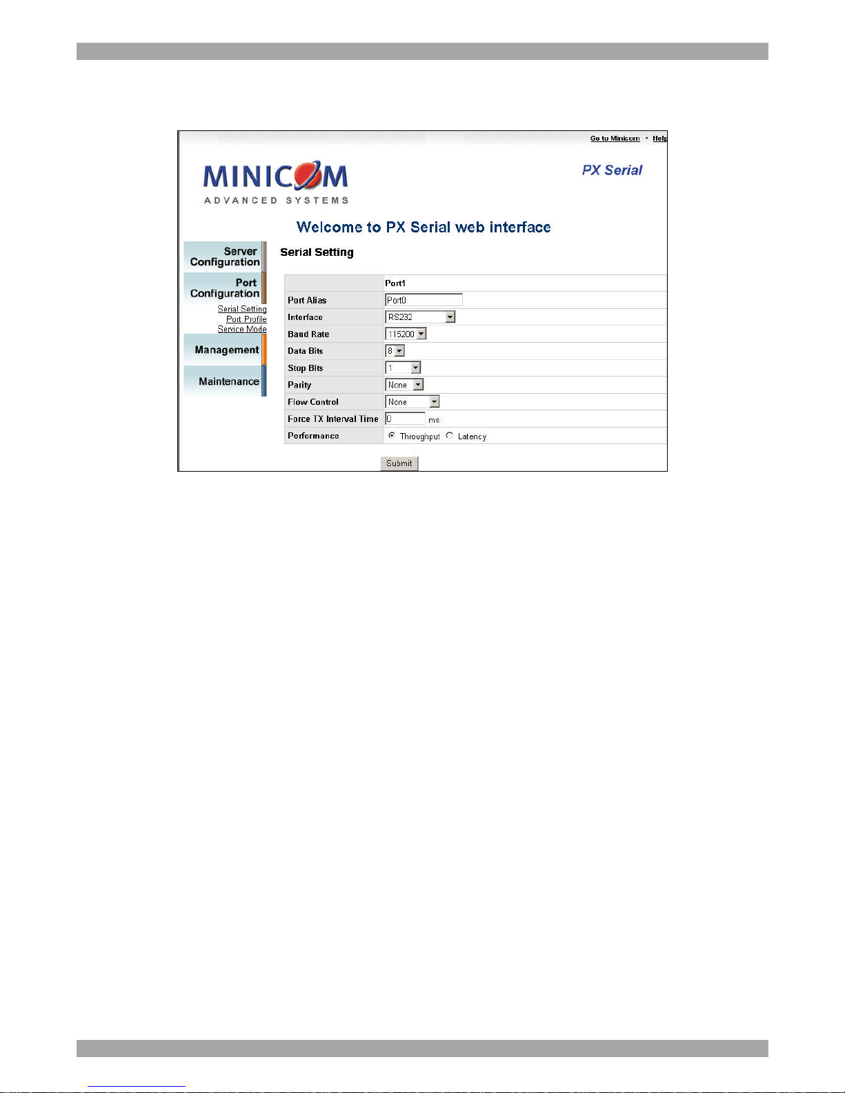
7.1 Serial Setting
Click Serial Setting, the following appears.
Figure 5 Serial Setting
Port Alias: Give the port an identifying name to be identified by the connected
device.
Select the Interface: RS232 / RS422 / RS485 (2-wires) / RS485(4-wires)
Select the settings for Baud rate, Data Bits, Stop Bits, Parity and Flow Control.
Force TX interval time is to specify a timeout when no data has been transmitted.
When the timeout is reached or TX buffer is full (4K Bytes), the queued data will be
sent. Zero (factory default) means disabled.
Performance options: Select Throughput for the fastest possible transmission speed.
Select Latency for the shortest response time.
Page 8
PX SERIAL
7
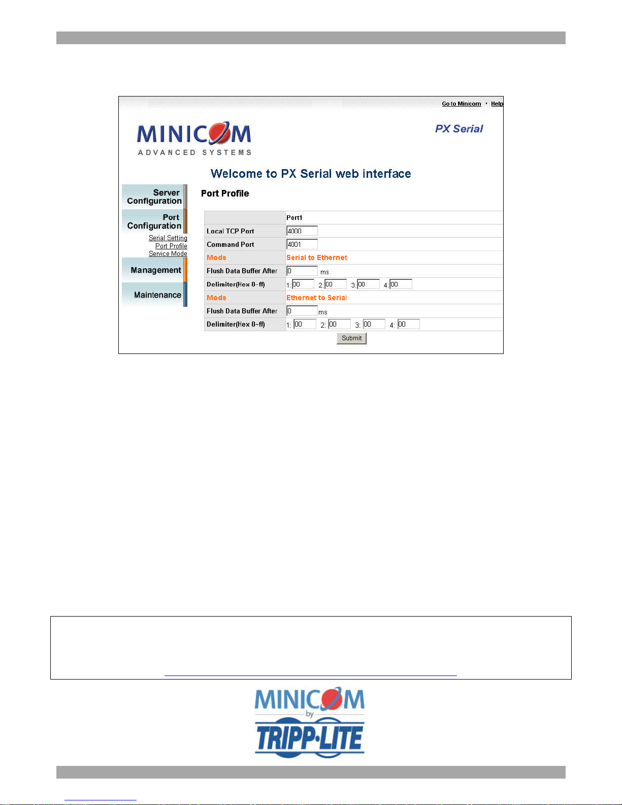
7.2 Port Profile
Click Port Profile, the following appears.
Figure 6 Port Profile
For advanced data packing options, you can specify delimiters for Serial to Ethernet
and / or Ethernet to Serial communications.
You can define up to a maximum of 4 delimiters (00~FF, HEX) for each way. The
data will be held until the delimiters are received or the optional “Flush Ethernet to
Serial data buffer” times out. Zero means disable (factory default).
8. Operating the device
Once configured, use a Telnet console or similar application - PuTTY, Tera Term,
Secure CRT - to connect to the PX Serial and operate the Serial device. Connect via
the telnet software to the PX IP address to port 4000.
For the rest of the configuration and operating instructions please see the softcopy
User Guide on the supplied CD or on our website
http://www.minicom.com/supportuserguides.htm
201205037 • 933210_EN
 Loading...