

Page 1
International HQ
Jerusalem, Israel
Tel: + 972 2 535 9666
North American HQ
Linden, New Jersey
Tel: + 1 908 4862100
European HQ
Dübendorf, Switzerland
Tel: + 41 1 823 8000
Italy
Rome
Tel: + 39 06 8209 7902
www.minicom.com Customer support - [email protected]
5UM30096 V2.3 12/03
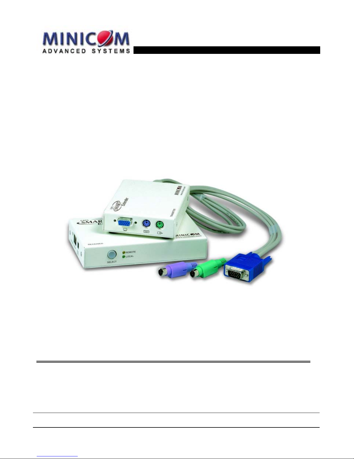
CAT5 Smart KVM Extender
User Guide
Page 2

CAT5 SMART KVM EXTENDER
1
Table of Contents
1. Welcome................................................................................... 2
2. Introduction ............................................................................. 3
3. The system components ........................................................ 3
4. The KVM Extender units ......................................................... 4
5. Pre-installation instructions................................................... 5
6. The KVM Extender cables ...................................................... 6
The 3 in 1 CPU cable ............................................................... 6
7. Power supply ........................................................................... 6
8. The KVM Extender as an extender ........................................ 7
9. Giving 2 users access to 1 computer.................................... 8
10. The KVM Extender as a 2-port KVM Switch.......................... 9
11. Operating the KVM Extender................................................ 10
Adjusting the picture ............................................................ 10
Timeout .................................................................................. 10
Locking KVM control ............................................................ 11
12. KVM Extender Settings mode .............................................. 11
Changing the hotkey............................................................. 12
Changing the Timeout period .............................................. 12
Enabling/disabling lock control ........................................... 12
Making advanced adjustments ............................................ 13
Replacing a computer........................................................... 13
Keyboard settings when replacing a computer ................. 14
Mouse driver settings when replacing a computer............ 14
Replacing a mouse type ....................................................... 15
Viewing the settings.............................................................. 16
Exiting the Settings mode .................................................... 16
13. Cascading Smart Extenders................................................. 17
Transmitter Power adapter................................................... 18
Switching on .......................................................................... 18
14. Technical specifications....................................................... 19
15. KVM Extender configuration ................................................ 20
Page 3

USER GUIDE
2
1. Welcome
The CAT5 Smart KVM Extender system is produced by Minicom
Advanced Systems Limited.
Technical precautions
This equipment generates radio frequency energy and if not installed in
accordance with the manufacturer’s instructions, may cause radio
frequency interference.
This equipment complies with Part 15, Subpart J of the FCC rules for a
Class A computing device. This equipment also complies with the
Class A limits for radio noise emission from digital apparatus set out in
the Radio Interference Regulation of the Canadian Department of
Communications. These above rules are designed to provide
reasonable protection against such interference when operating the
equipment in a commercial environment. If operation of this equipment
in a residential area causes radio frequency interference, the user, and
not Minicom Advanced Systems Limited, will be responsible.
Changes or modifications made to this equipment not expressly
approved by Minicom Advanced Systems Limited could void the
user’s authority to operate the equipment.
Minicom Advanced Systems Limited assumes no responsibility for any
errors that appear in this document. Information in this document is
subject to change without notice.
No part of this document may be reproduced or transmitted in any form
or by any means, electronic or mechanical, for any purpose, without
the express written permission of Minicom Advanced Systems
Limited.
© 2003 Minicom Advanced Systems Limited. All rights reserved.
Trademarks
PS/2 is a registered trademark of International Business Machines
Corporation. All other trademarks and registered trademarks are the
property of their respective owners.
Page 4
CAT5 SMART KVM EXTENDER
3
2. Introduction
The CAT5 Smart KVM Extender (KVM Extender) system from
Minicom is an advanced KVM switch that performs the
following functions:
• Extends KVM control over a computer* up to a
distance of 110m / 360ft
• Gives 2 users at 2 workstations control of 1 computer*
• A 2-port KVM Switch for 1 or 2 users
* Wherever the word ‘computer’ appears in this guide it can
equally refer to a KVM switch.
3. The system components
The KVM Extender system consists of the following:
• Transmitter
• Receiver
• 3 in 1 CPU cable
• 1 Power adapter for the Receiver
A Shielded CAT5 FTP (Foil Shielded Twisted Pair) Solid
Wire 2x4x24 AWG cable terminated with RJ-45M connectors
connects the KVM Extender system. The Receiver can be up
to 110m/360ft away from the Transmitter.
This Guide illustrates the KVM Extender system and explains
how to install and operate it.
Page 5

USER GUIDE
4
4. The KVM Extender units
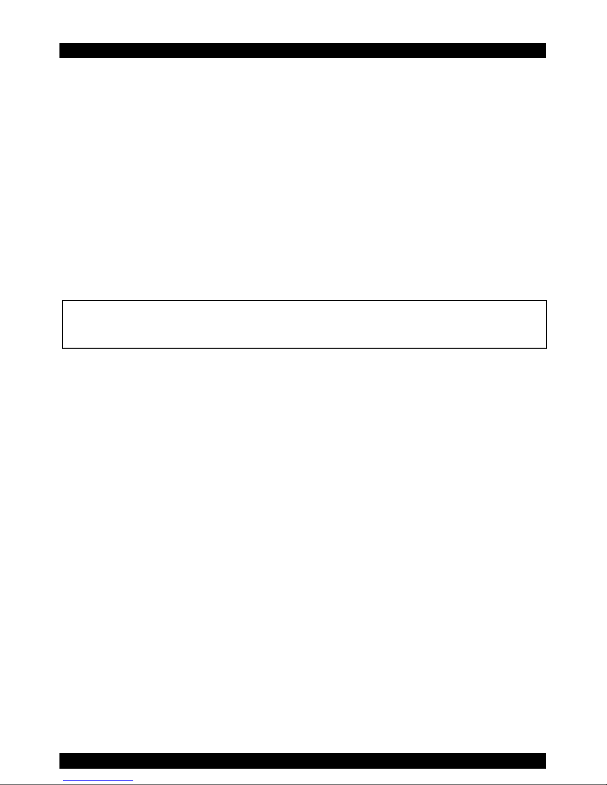
The figures below illustrate the Transmitter and Receiver units.
SYSTEM
CPU
Built-in KVM
cables
System
cable
Power
connector
6VDC
LEDs
Mouse
Monitor
Keyboard
Side A Side B
Figure 1 The 2 Transmitter side panels
SELECT
POWER
CONTROL
Select
button
LEDs
Figure 2 The Receiver front panel
Page 6
CAT5 SMART KVM EXTENDER
5
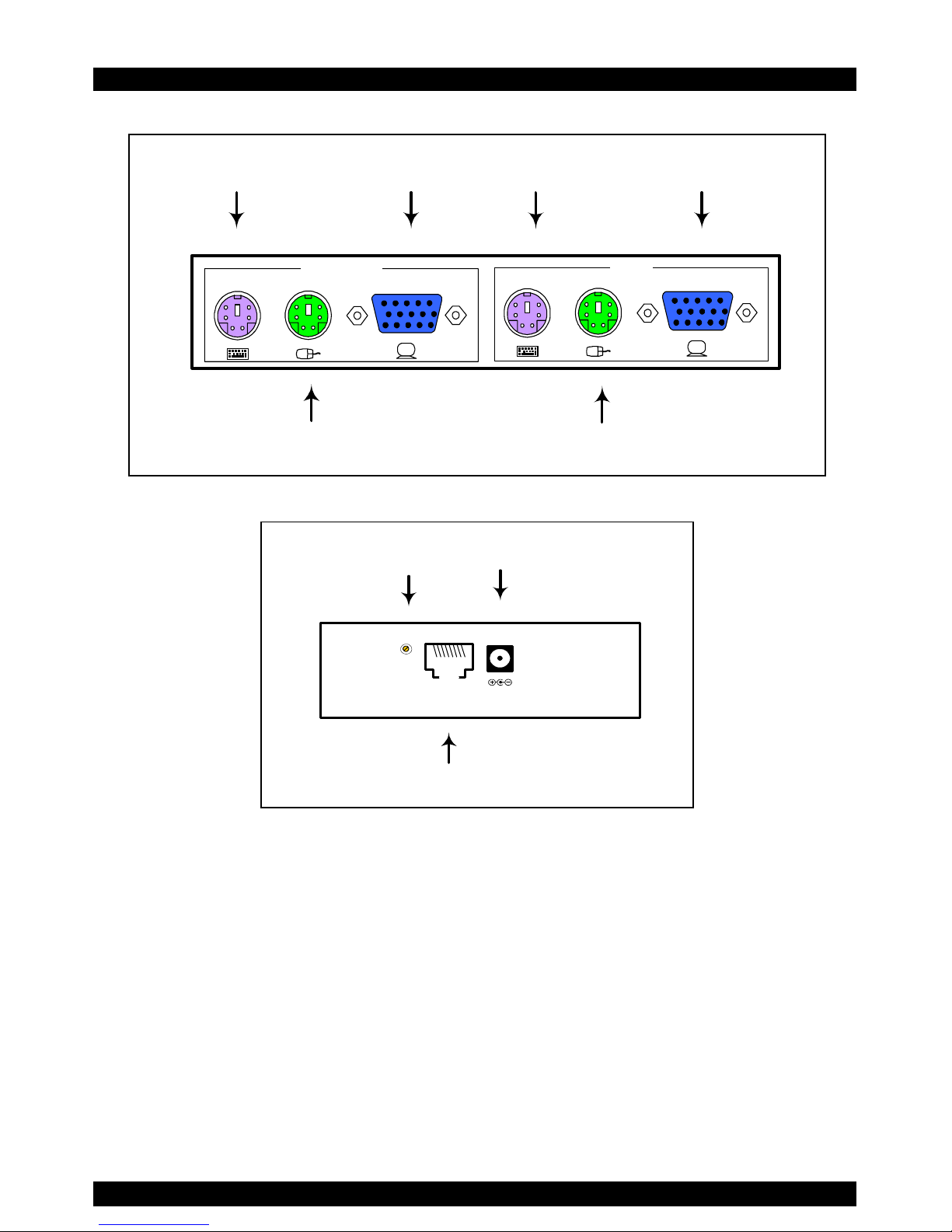
COMPUTER
USER
Keyboard
Mouse
Monitor
Computer
Mouse port
Computer Keyboard
port
Computer
Monitor port
Figure 3 The Receiver rear panel
6VDC
SYSTEMPICTURE
Picture
adjuster
System
cable
Power
connector
Figure 4 The Receiver side panel
5. Pre-installation instructions
Disconnect all computers from the electrical power supply.
Place cables away from fluorescent lights, air conditioners,
and machines that are likely to generate electrical noise.
Page 7
USER GUIDE
6
6. The KVM Extender cables
The Transmitter comes with built-in KVM cables that connect
to the computer’s Video card, Mouse and Keyboard ports.
The 3 in 1 CPU cable
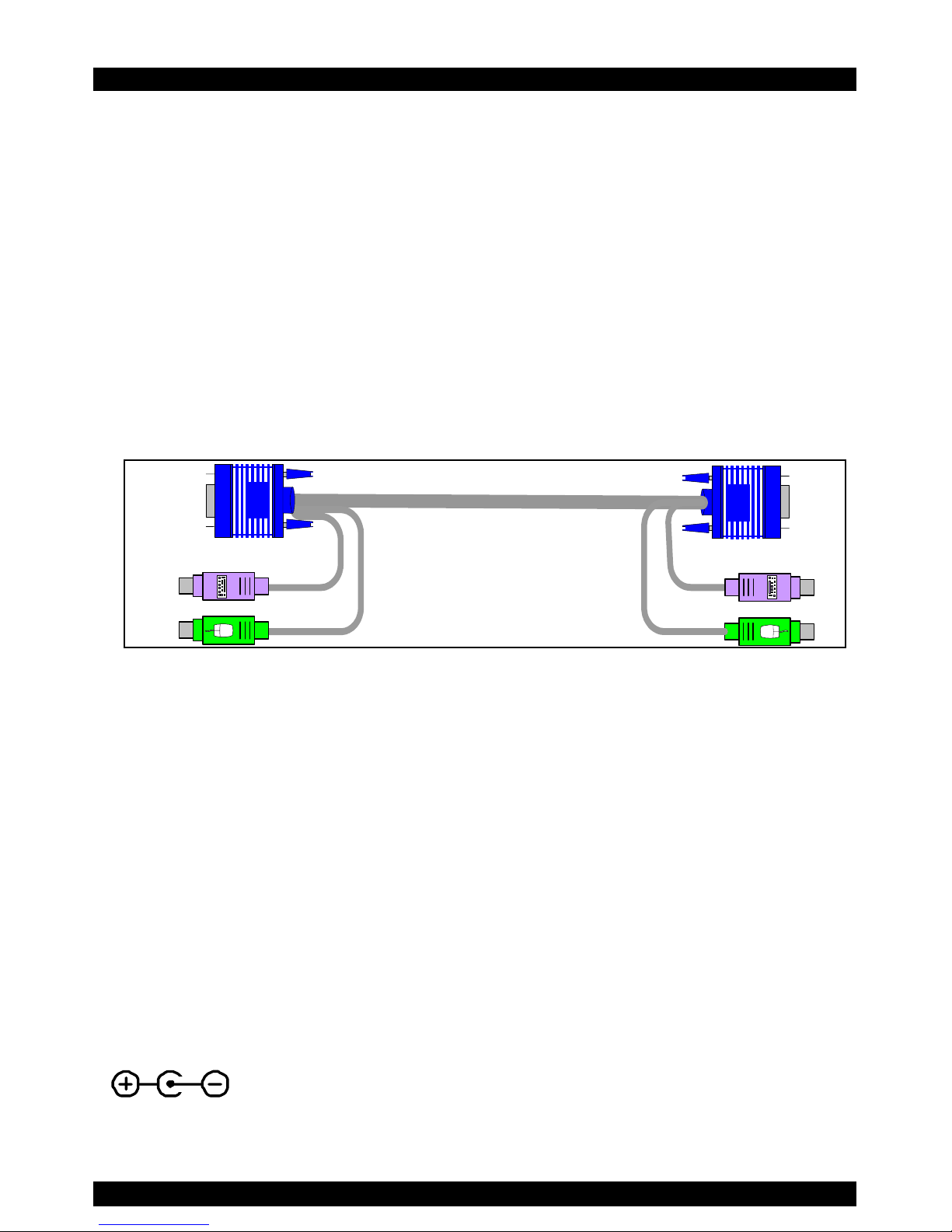
The 3 in 1 CPU cable –illustrated below – is only used when
the Receiver connects to a computer. The cable connects to the
Computer section of the Receiver rear panel, see Figure 3.
Figure 5 The 3 in 1 CPU cable
7. Power supply
Connect the Receiver to the power supply with the Power
adapter and Power cord provided.
The Transmitter receives its power from the connected
computer and does not generally need an external power supply.
However, when cascading Smart Extenders, some of the
Transmitters need an external power supply. Use a Minicom
Power adapter p/n 5PS20025. The power supply specifications
are: Regulated 6VDC 2 Amp, minus on internal pin
. Cascading is discussed on page 17.
Page 8
CAT5 SMART KVM EXTENDER
7
8. The KVM Extender as an extender
Extend the KVM workstation from the computer up to a
distance of 110m/360ft.
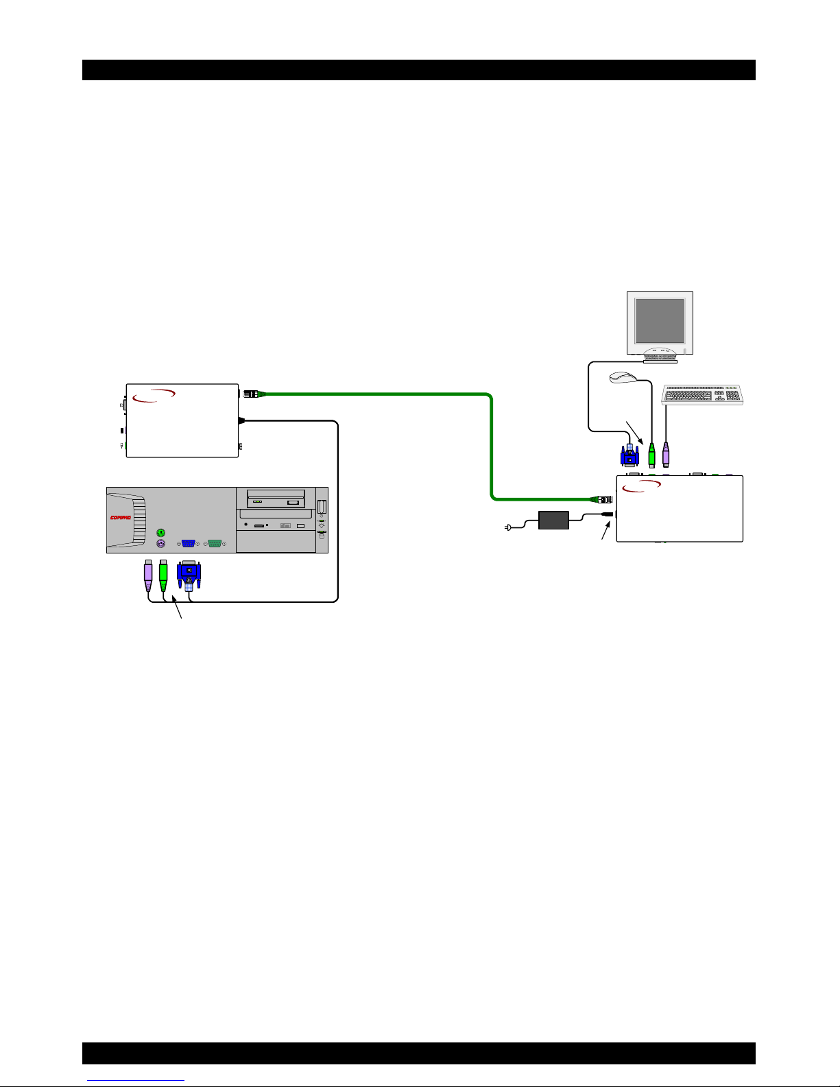
To use the KVM Extender as an extender, connect the system as
in Figure 6.
6VDC
To Video card
SD
DESKPRO
Ω
To wall
socket
SD
P110
Computer
To
Keyboard
port
To Mouse port
Transmitter
Receiver
To System port
CAT5 FTP cable
Up to 110m / 360ft
Power
adapter
To
Power
port
To User Monitor port
To User
Keyboard port
To User
Mouse
port
To System port
CAT5
SMART
Extender
RECEIVER
MINICOM
www.minicom.co m
CAT5
SMART
Extender
TRANSMITTER
MINICOM
www.minicom.com
Figure 6 The KVM Extender as an extender
Page 9
USER GUIDE
8
9. Giving 2 users access to 1 computer
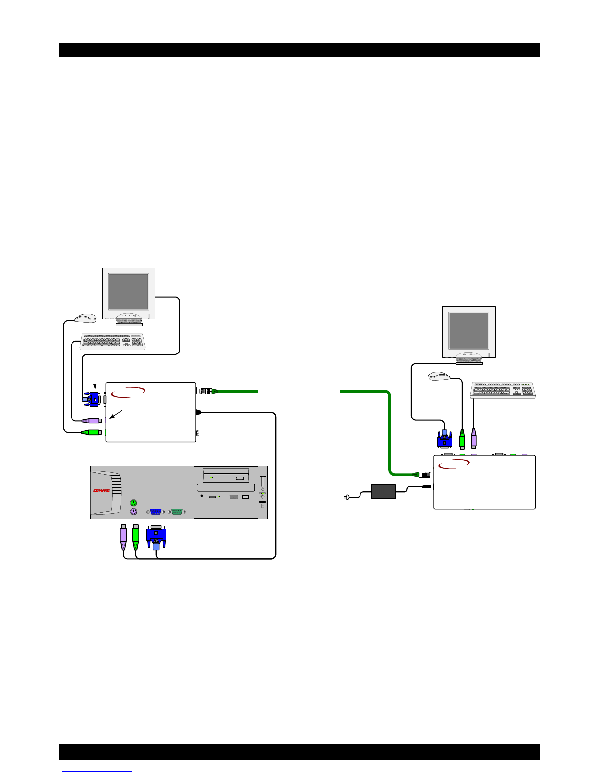
To give 2 users access to 1 computer connect the system as in
Figure 7.
The connections are the same as in Figure 6, with the addition
of a KVM workstation for user 2.
Access to the computer is on a first-come-first-served basis.
6VDC
SD
DESKPRO
Ω
SD
P110
Computer
Transmitter
Receiver
CAT5 FTP cable
Up to 110m / 360ft
To Monitor port
SD
P110
To Keyboard
port
To Mouse
port
User 1
User 2
CAT5
SMART
Extender
RECEIVER
MINICOM
www.minicom. com
CAT5
SMART
Extender
TRANSMITTER
MINICOM
www.minicom.com
Figure 7 Giving 2 users access to 1 computer
Page 10
CAT5 SMART KVM EXTENDER
9
10. The KVM Extender as a 2-port KVM Switch
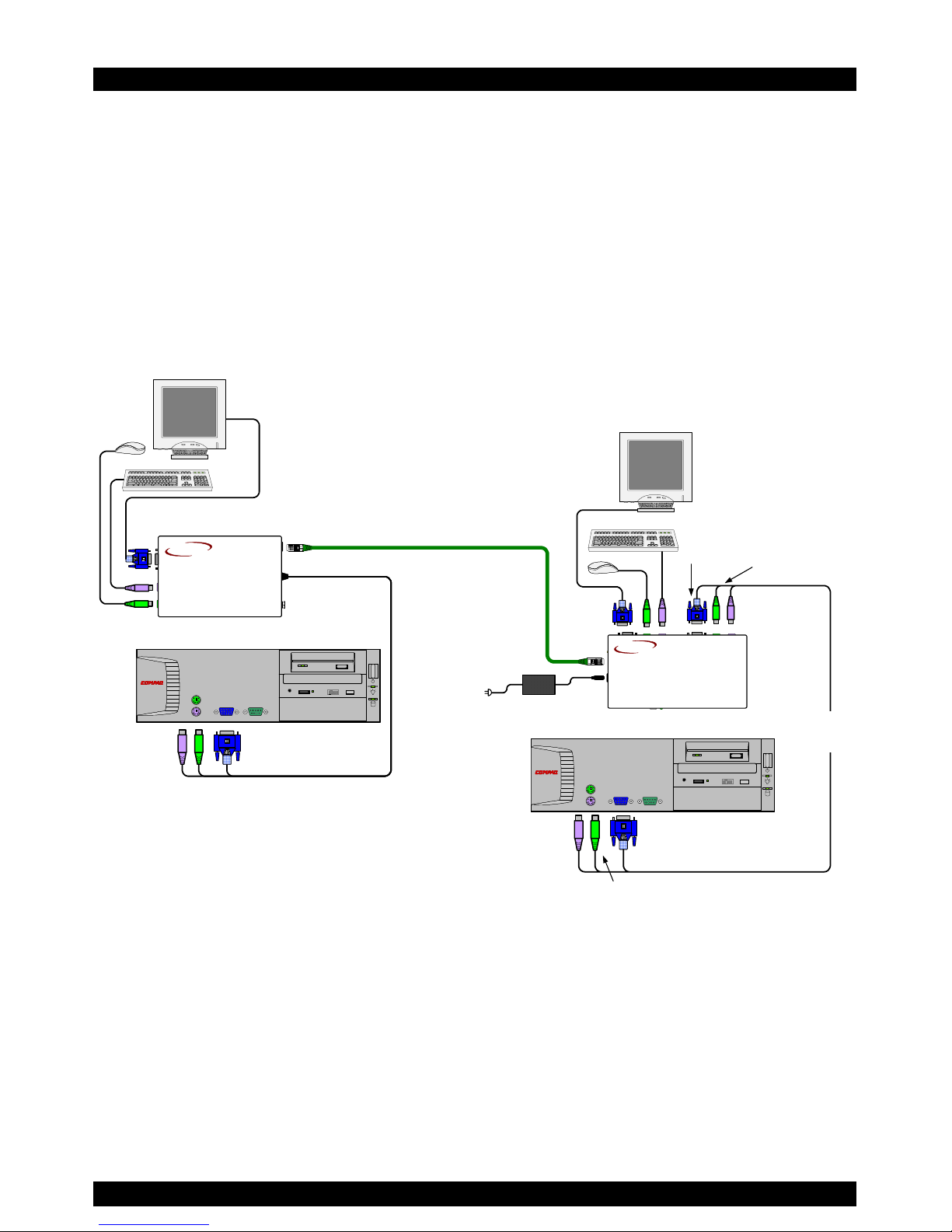
Figure 8 illustrates the system connected to 2 computers and 2
workstations. User 1 can access his local computer or the
remote computer. User 2 can only access his local computer.
The connections are the same as in Figure 7, with the addition
of the 3 in 1 CPU cable that connects a 2
nd
computer to the
Receiver.
6VDC
SD
DESKPRO
Ω
SD
P110
Computer
Transmitter
Receiver
CAT5 FTP cable
Up to 110m / 360ft
SD
P110
User 1
User 2
3 in 1
CPU
cable
SD
DESKPRO
Ω
To Video card
To
Keyboard
port
To Mouse port
To Computer
Monitor port
To Computer
Keyboard port
To Computer
Mouse port
Computer
CAT5
SMART
Extender
RECEIVER
MINICOM
www.minicom.com
CAT5
SMART
Extender
TRANSMITTER
MINICOM
www.minicom.com
Figure 8 As a 2-port KVM Switch
The option in Figure 8 can also work with only 1 user
workstation connected at the Receiver.
There is another configuration diagram on the last page of this
Guide, and more on the Marketing & Documentation CD.
Page 11

USER GUIDE
10
11. Operating the KVM Extender
Once the system is connected there are 2 ways to switch
between the 2 computers / KVM workstations.
• On the Receiver press the Select button
Or
• On the keyboard press Shift followed by + or -.
When the Receiver works at its computer, its Control LED is
off. When the Receiver controls the Transmitter computer its
LED is on. The Receiver’s LED blinks when the Transmitter
controls its own computer.
At the Transmitter its Control LED remains off unless the
Receiver is working on the Transmitter computer.
Adjusting the picture
When the Receiver has control of the Transmitter’s computer,
adjust the picture quality where necessary using a small flat
screwdriver to turn the Picture adjuster located on the
Receiver’s rear panel. See Figure 4.
Timeout
When there are 2 workstations in the system you can gain
control at each workstation when the other workstation is idle
for 2 seconds. This timeout period can be altered in the settings
mode to between 1-99 seconds, as explained below.
Page 12

CAT5 SMART KVM EXTENDER
11
Locking KVM control
When there are 2 users using the system, either user can
override the Timeout feature and retain control indefinitely. Do
so by locking the system so that only one user has control.
To lock control:
On the keyboard press Shift followed by F12.
To relinquish control:
On the keyboard press Shift followed by Esc.
In the settings mode you can disable the lock control function.
This is explained in the Settings mode paragraph below.
12. KVM Extender Settings mode
Enter the Settings mode to:
• Change the hotkey
• Change the Timeout period
• Enable/disable lock control
• Make advanced adjustments
• View settings
To enter the Settings mode:
Press Shift then, F2. Release Shift before pressing F2. All 3
keyboard LEDs glow when in the Settings mode.
Page 13

USER GUIDE
12
Changing the hotkey
You can change the hotkey from Shift to Alt or Ctrl. Once
changed, all references in this Guide to Shift now refer to the
new hotkey.
To change the hotkey in the Settings mode:
To Type the letters
Alt HA
Ctrl HC
Shift HS
Changing the Timeout period
To change the Timeout period in the Settings mode:
Press T followed by a 2-digit time period of between 01-99
seconds. The 3 keyboard LEDs blink and the new setting is now
functional.
Enabling/disabling lock control
By default both users can lock control. You can disable the lock
control function.
To disable lock control type DL.
To enable lock control type EL.
Page 14

CAT5 SMART KVM EXTENDER
13
Making advanced adjustments
The KVM Extender operates with:
• Windows, Linux, Novell or UNIX systems
• 2 or 3 or 5 button PS/2 mouse, Intellimouse or Wheel
mouse
When connected and switched on as set out above, the KVM
Extender automatically operates with the computer and mouse
types connected to it.
Replacing a computer
When a computer is replaced with a different computer type
while the KVM Extender is in use, we recommend turning the
new computer off before connecting it to the KVM Extender.
When turning the computers off is inconvenient, do the
following:
In the Settings mode adjust the KVM Extender keyboard and
mouse modes to be compatible with the new computer. See the
tables below.
Page 15

USER GUIDE
14
Keyboard settings when replacing a computer
For Type the letters
PC (Windows, Linux,
Novell)
PC
UNIX console mode UC
UNIX graphics mode UG
Set the keyboard mode setting to:
• PC when operating Intel based computers.
• UC when operating UNIX computers in console mode.
• UG when operating UNIX computers in graphics mode.
Mouse driver settings when replacing a computer
For Type the letters
Wheel mouse or Intellimouse IN
2 or 3 button mouse PS
5-button mouse EP
Page 16

CAT5 SMART KVM EXTENDER
15
Set the mouse setting to IN when the computer has an operating
system that supports Wheel mouse functionality: (Windows 98
and Linux*).
Set the mouse setting to PS when the computer has an operating
system that does not support Wheel mouse functionality:
(Windows 95, NT4, DOS, Linux*, UNIX and Novell).
*Depending on the version.
Set the mouse setting to EP when the computer has an operating
system that supports Explorer mouse functionality: (Windows –
ME, 2000, and XP).
Replacing a mouse type
When a mouse is replaced with a different mouse type (not
necessarily a different mouse) while the KVM Extender is in
use, press and hold the Select button for more than 5 seconds.
Release the Select button after your monitor blinks once.
Page 17

USER GUIDE
16
Viewing the settings
View the settings and firmware revision in any text editor.
To view the settings:
1. Before entering to the Settings mode switch the keyboard
layout to English.
2. Open any text editor, e.g. Notepad.
3. Press Shift, followed by F2 to enter the Settings mode.
4. Press F. The settings appear in the text editor.
Exiting the Settings mode
To save changes and exit the Settings mode:
Press Esc.
Page 18
CAT5 SMART KVM EXTENDER
17
13. Cascading Smart Extenders
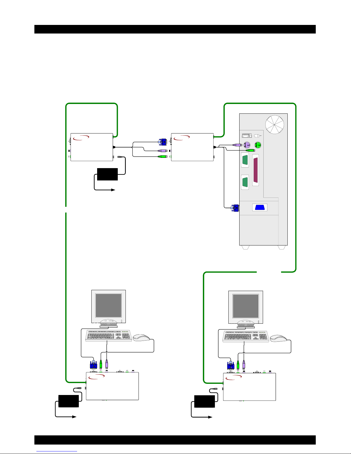
Cascade two or more Smart Extenders to get more than one
remote workstation working from one computer. One possible
configuration is shown on the diagram below.
SYSTEM
6VDC
SD
P110
SYSTEM
6VDC
6VDC
SYSTEMPICTURE
SELECT
USERCOMPUTER
SD
P110
6VDC
SYSTEMPICTURE
SELECT
USERCOMPUTER
CAT5 Cable
CAT5 Cable
Remote
Workstation 2
Remote
Workstation 1
Smart Extender
Transmitter 1
Smart Extender
Transmitter 2
Smart Extender Receiver 2
Smart Extender Receiver 1
Power Supply
+6VDC 2A
To Wall Socket
Power Supply
+6VDC 2A
To Wall Socket
Power Supply
+6VDC 2A
To Wall Socket
CAT5
SMART
Extender
TRANSMITTER
MINICOM
www.minicom.com
CAT5
SMART
Extender
TRANSMITTER
MINICOM
www.minicom.com
CAT5
SMART
Extender
RECEIVER
MINICOM
www.minicom.com
CAT5
SMART
Extender
RECEIVER
MINICOM
www.minicom.com
Figure 9 Cascading Smart extenders
Page 19

USER GUIDE
18
Transmitter Power adapter
To ensure mouse and keyboard functionality when cascading,
connect an external Minicom Power adapter +6VDC 2A (P/N
5PS20025) and Power cord (P/N 5CB60431) to the second
Transmitter unit. See Figure 9 above.
Switching on
Switch the system on in the following order:
1. The second Smart Extender Transmitter unit
2. The rest of the system, including the shared computer.
Page 20

CAT5 SMART KVM EXTENDER
19
14. Technical specifications
System
System cable CAT5 FTP cable 2x4x24 AWG Solid Wire
Maximum distance 110m/360ft
Mouse support: 2 or 3 or 5 button PS/2, Wheelmouse
Operating systems DOS, Windows (3x, 9x, 2000, NT, ME, XP),
Novell, Linux, UNIX, HP UX, QNX, SGI,
FreeBSD, BeOS, Open VMS
Screen resolution Up to 1600X1200 @ 75Hz (depends on
cable length)
Operating temperature 0°C to 50°C
Storage temperature -40°C to 70°C
Transmitter Receiver
Cables Built-in KVM 3 in 1 CPU
Connectors VGA – HDD15M
Keyboard – MiniDin6M
Mouse – MiniDin6M
System – RJ45
VGA – HDD15F
Keyboard – MiniDin6F
Mouse – MiniDin6F
System - RJ45
Dimensions 85 x 113 x 25mm/
0.28 x 0.37 x 0.08ft
85 x 49 x 25mm/
0.28 x 0.49 x 0.08ft
Weight 380g
Shipping weight 1.70 Kg
Power supply From computer keyboard
5V 220mA
External power
adapter 6VDC 2A
Page 21
USER GUIDE
20
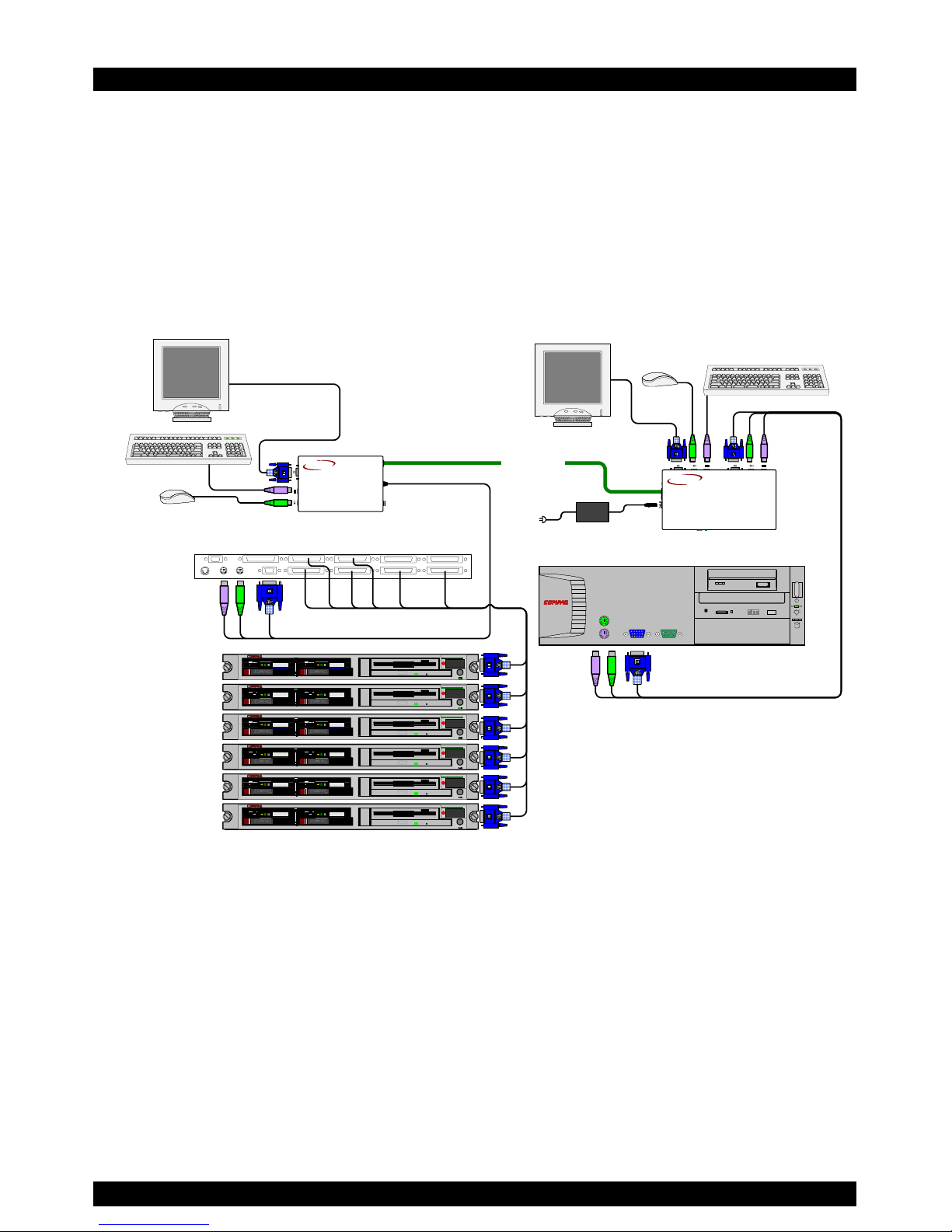
15. KVM Extender configuration
In Figure 10 the KVM Extender system is connected to a KVM
Switch and computer rack. User 1 can access his local computer
or the computer rack through the KVM Switch. User 2 can
access the computer rack through the KVM Switch.
CAT5 cable
6VDC
SYSTEMPICTURE
SELE
CT
USERCOMPUTER
SYSTEM
SD
DESKPRO
Ω
COMPUTER 1 COMPUTER 2
COMPUTER 6COMPUTER 5STATION 2
SCREENPS/2 MOUSEKB
POWER
SERIAL MOUSE
COMPUTER 3 COMPUTER 4
COMPUTER 8COMPUTER 7
KVM Switch
SD
P110
ProLiant DL360
9.1 - GB
10k
ULTRA2 SCSI
9.1 - GB
10k
ULTRA2 SCSI
ProLiant DL360
9.1 - GB
10k
ULTRA2 SCSI
9.1 - GB
10k
ULTRA2 SCSI
ProLiant DL360
9.1 - GB
10k
ULTRA2 SCSI
9.1 - GB
10k
ULTRA2 SCSI
ProLiant DL360
9.1 - GB
10k
ULTRA2 SCSI
9.1 - GB
10k
ULTRA2 SCSI
ProLiant DL360
9.1 - GB
10k
ULTRA2 SCSI
9.1 - GB
10k
ULTRA2 SCSI
ProLiant DL360
9.1 - GB
10k
ULTRA2 SCSI
9.1 - GB
10k
ULTRA2 SCSI
Transmitter
Receiver
SD
P110
Computer rack
User 1
User 2
CAT5
SMART
Extender
RECEIVER
MINICOM
www.minicom.com
CAT5
SMART
Extender
TRANSMITTER
MINICOM
www.minicom.com
6VDC
Figure 10 KVM Extender with a KVM switch
Page 22

21
 Loading...