

Page 1
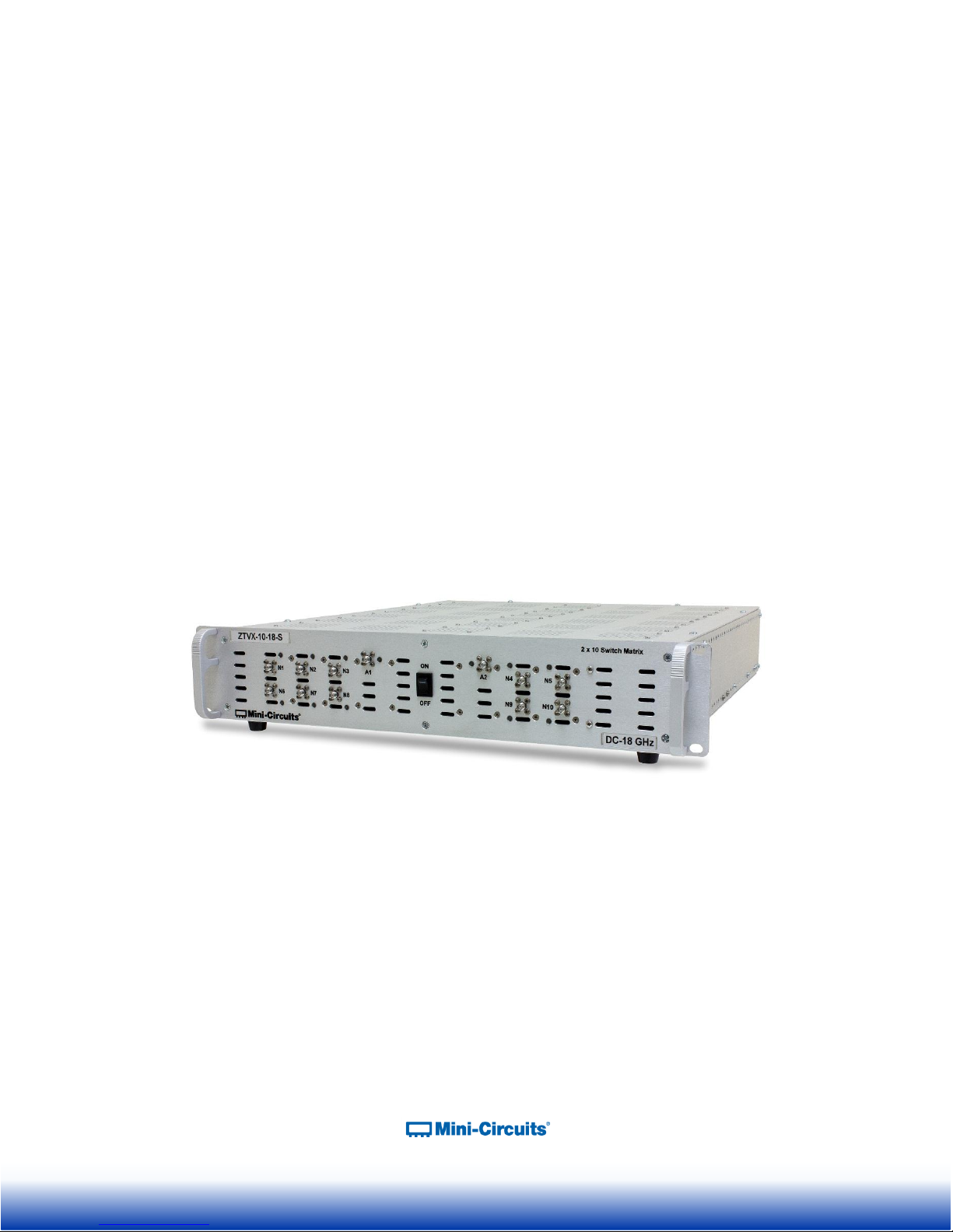
ZTVX-Series RF Signal Routing Assembly
2 x N Port Switch Matrix
50Ω
A Mini-Circuits Self-Contained Integrated Assembly
User’s Manual
1
Page 2

Important Notice
This guide is owned by Mini-Circuits and is protected by copyright, trademark and other intellectual
property laws.
The information in this guide is provided by Mini-Circuits as an accommodation to our customers and may
be used only to promote and accompany the purchase of Mini-Circuits’ Parts. This guide may not be
reproduced, modified, distributed, published, stored in an electronic database, or transmitted and the
information contained herein may not be exploited in any form or by any means, electronic, mechanical
recording or otherwise, without prior written permission from Mini-Circuits.
This guide is subject to change, qualifications, variations, adjustments or modifications without notice and
may contain errors, omissions, inaccuracies, mistakes or deficiencies. Mini-Circuits assumes no
responsibility for, and will have no liability on account of, any of the foregoing. Accordingly, this guide
should be used as a guideline only.
Trademarks
Microsoft, Windows, Visual Basic, Visual C# and Visual C++ are registered trademarks of Microsoft
Corporation. LabVIEW and CVI are registered trademarks of National Instruments Corporation. Delphi is
a registered trademark of Delphi Technologies, Inc. MATLAB is a registered trademark of The
MathWorks, Inc. Agilent VEE is a registered trademark of Agilent Technologies, Inc. Linux is a registered
trademark of Linus Torvalds. Mac is a registered trademark of Apple Inc. Python is a registered trademark
of Python Software Foundation Corporation.
All other trademarks cited within this guide are the property of their respective owners. Neither MiniCircuits nor the Mini-Circuits ZTVX-Series are affiliated with or endorsed or sponsored by the owners of
the above referenced trademarks.
Mini-Circuits and the Mini-Circuits logo are registered trademarks of Scientific Components Corporation.
Mini-Circuits
13 Neptune Avenue
Brooklyn, NY 11235
Phone: 1-718-934-4500
Email: sales@minicircuits.com
Web: www.minicircuits.com
Version 10/18/16
© Mini-Circuits, 2016. All rights reserved.
2
Page 3

CONTENTS
1 INTRODUCTION .................................................................................................................... 4
2 WARNINGS ........................................................................................................................... 5
2.1 Safety Hazards ................................................................................................................. 5
2.2 Additional Precautions ...................................................................................................... 6
3 PHYSICAL DESCRIPTION ..................................................................................................... 7
4 FUNCTIONAL DESCRIPTION ................................................................................................ 8
5 UNPACKING ........................................................................................................................... 9
Unpacking Process ........................................................................................................... 9
Package Contents ............................................................................................................ 9
6 LAYOUT AND INSTALLATION .............................................................................................10
Rack Mounting .................................................................................................................10
Rear Panel Safety Blocks ................................................................................................10
Rear Panel Grounding Stud .............................................................................................11
7 SOFTWARE ..........................................................................................................................12
Software Overview...........................................................................................................12
Installing the GUI Software ..............................................................................................12
Using the ZTVX GUI ........................................................................................................15
7.3.1 Connecting to the ZTVX ............................................................................................15
7.3.2 GUI Displays and Built-In Reference .........................................................................20
7.3.3 Sending Commands ..................................................................................................23
Updating Firmware ..........................................................................................................30
Programming Support ......................................................................................................32
8 RETURN MATERIAL AUTHORIZATION (RMA) PROCEDURE ............................................33
9 APPENDIX: ELECTRICAL SCHEMATICS ............................................................................34
3
Page 4

1 INTRODUCTION
Chi Man Shum
Phone: +1 201 647-1615
Email: chiman@minicircuits.com
chimanshum@gmail.com
Lee Whiting
+44 1252 832 620
Email: Lee@uk.minicircuits.com
Thank you for choosing Mini-Circuits custom test equipment to meet your needs! The purpose
of this User’s Manual is to instruct you on basic installation and setup of your ZTVX-unit, to
advise you on general precautions to be taken when installing and handling the equipment, and
to provide instruction on installing and using the control software for this unit.
We’re here to support you every step of the way. For technical support and assistance, please
find the following points of contact for your convenience:
4
Page 5
2.1 Safety Hazards
Electrical Danger
The ZTVX-unit contains live 110/220V contacts and should be
used and handled only by qualified professionals. When
performing any activity in and around ZTVX-unit box, user
must exercise extreme caution to avoid touching any parts
where live voltage may be present to prevent injury or
death due to electrical shock.
Heavy Object
The ZTVX-unit box is heavy and requires caution to prevent
damage to the equipment and ensure user safety. User
must follow safe lifting protocols and use any necessary
lifting aids to prevent muscle strain or back injury. The unit
must be supported in rack structure by securely fastened
side rails or shelving to avoid potentially damaging the
equipment.
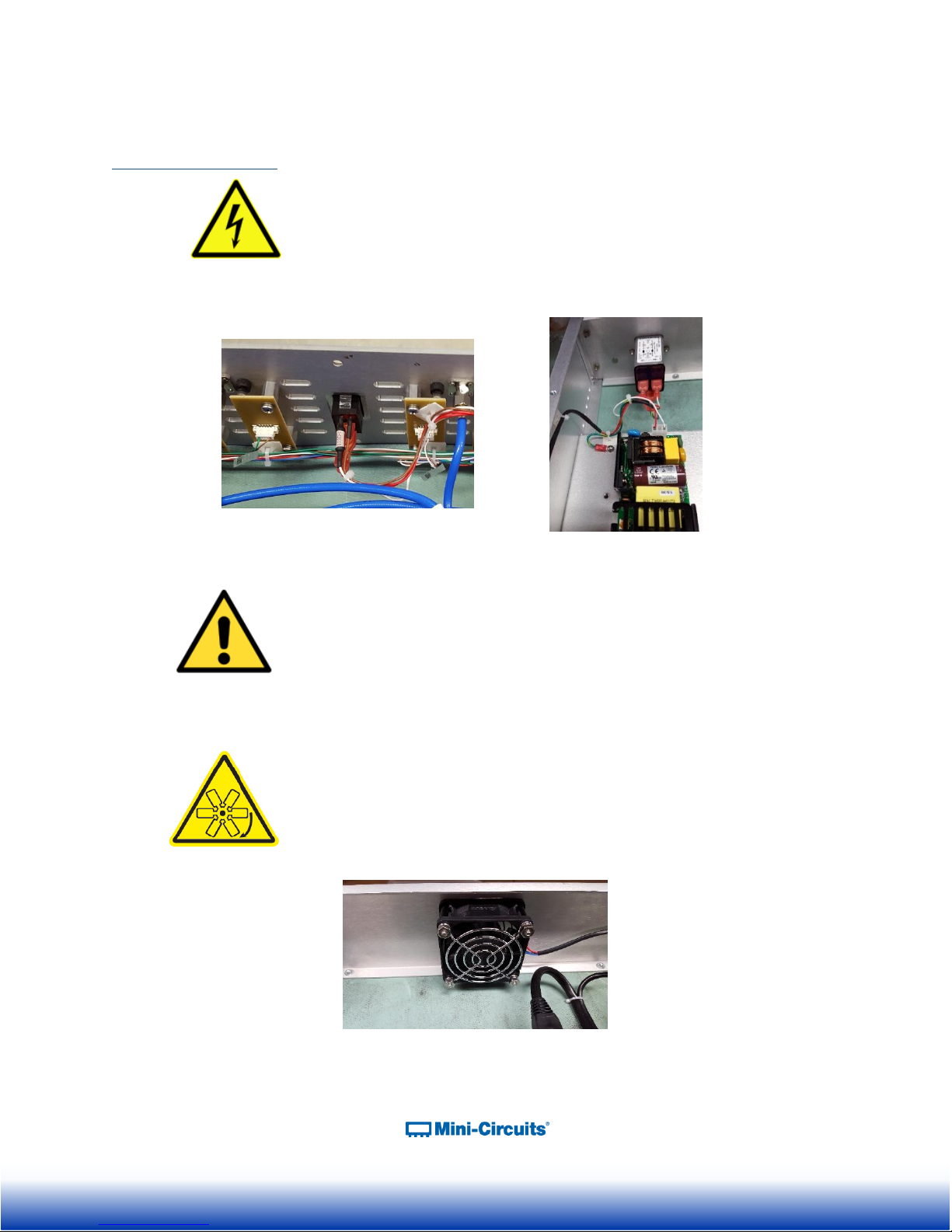
High Speed Fan Blades
The ZTVX-unit module contains cooling fans with rotating
blades that can cause serious injury or cut. Remove any
loose articles before working inside the ZTVX-unit case to
avoid getting caught in moving machinery.
Figure 2: Fan blades inside the ZTVX-Unit case
2 WARNINGS
Figure 1: Live 110 / 220V contacts inside ZTVX-UNIT box.
5
Page 6
2.2 Additional Precautions
1
1
Air Flow: ZTVX-unit box must be mounted by customer to maintain minimum 1U (1.75”)
free air space above and below each box with unobstructed access to room ambient airflow for
proper operation.
Electrostatic Discharge: Any person operating the ZTVX-unit must have Electrostatic
Discharge (ESD) protection to prevent damage to any components.
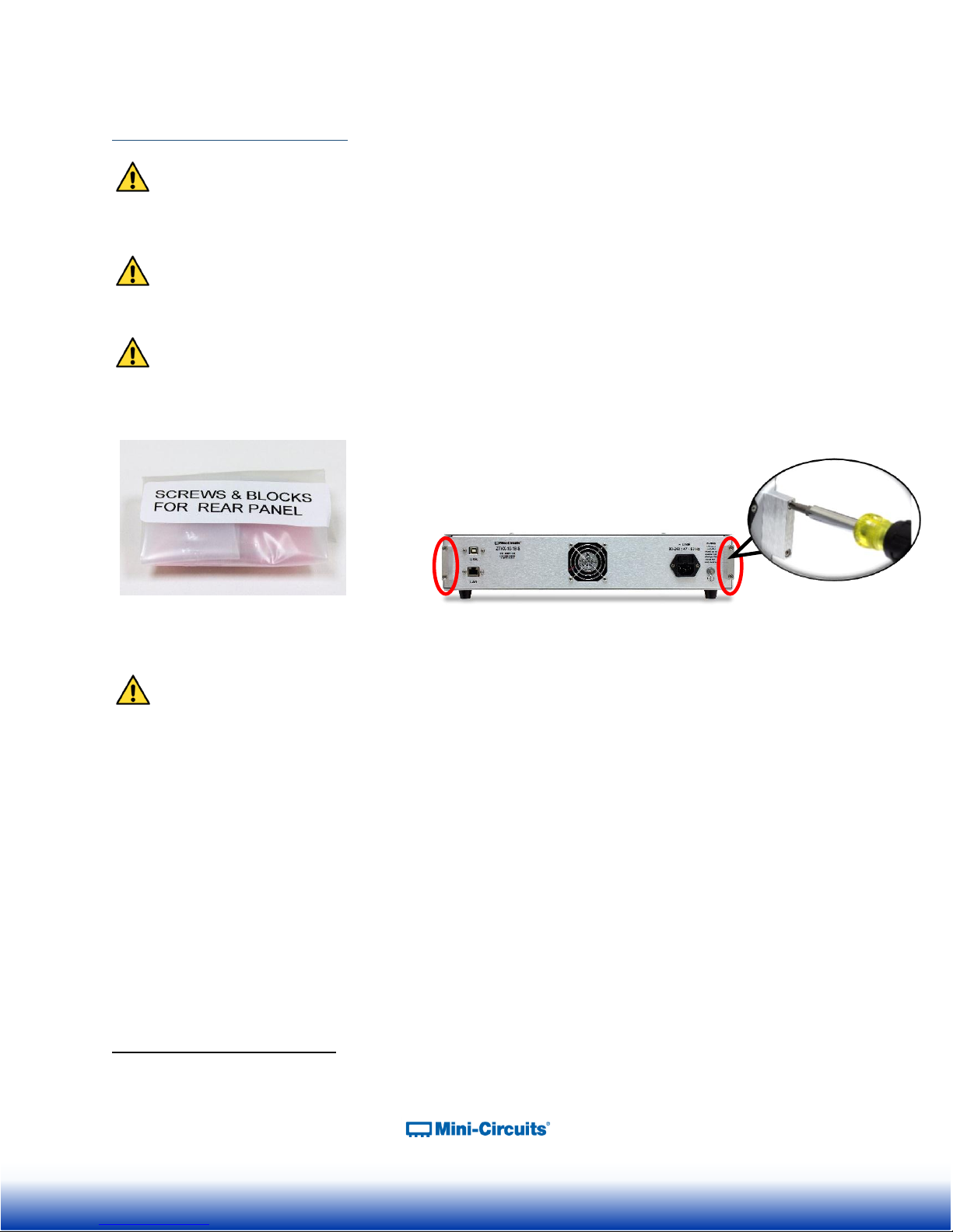
Rear Panel Safety Blocks: The ZTVX unit is supplied with two rear panel safety blocks that
must be installed by the customer. Failure to install safety blocks may result in damage to the
product. Refer to section 7.2 for additional instructions.
Opening & Tampering: This equipment is designed to be serviced only by professional
electrical technicians. Case openings by any person other than qualified personnel authorized by
Mini-Circuits or customer will void any and all terms of the Limited Warranty.
Although top and bottom panels create intended accessibility, it is important that caution be taken when connecting or
disconnecting any electrical or RF connection; moving, removing, or replacing any wires, cables, connections, switches, or
other components within the boxes to avoid potentially damaging or dislodging any other cables or connections.
6
Page 7

3 PHYSICAL DESCRIPTION
Mini-Circuits’ ZTVX-Series of 2 x N switch matrices come housed in an aluminum alloy chassis
measuring 19” wide x 3.48” (2U) high x 20” deep (483 x 89 x 508mm). The front panel is
fabricated with an array of slots to allow adequate air flow from the inside of the case and
facilitate cooling. The front panel of the unit is also configured with SMA-F or N-F connectors for
2 RF inputs (labeled A1 and A2) and up to 16 RF outputs (labeled N1 – N16), depending on your
model. Note that all switch ports are bi-directional and may be used as inputs or outputs as
desired. When the unit is on, RF input A1 is identified by a green LED light, and RF input A2 is
identified by an orange LED light. The unit is powered on with the power switch at the center of
the front panel which illuminates green when in the ON position. Two handles at left and right
ends of the front panel facilitate lifting and moving the unit, and the slotted holes on the outer left
and right extrusions allow secure mounting to a standard 19” (483mm) rack support structure.
Figure 3: Front panel of the ZTVX-unit. 2 x 10 configuration shown.
On the rear panel of the equipment case is the input for a 90-260V AC power supply with
caution label (right side). At the bottom right of the rear panel is a clearly marked grounding
terminal. It is recommended that this terminal be connected to a Common Bonding Network
(CBN) to properly ground the unit case. In the center of the rear panel is a cooling fan with a
protective cover. The identification sticker at the left of the rear panel displays the equipment
model name, serial number and internal control board number. At the far left of the rear panel
are connection ports for USB and RJ45 (LAN), allowing you to communicate with the equipment
from your PC.
Figure 4: Rear panel of the ZTVX-unit
7
Page 8
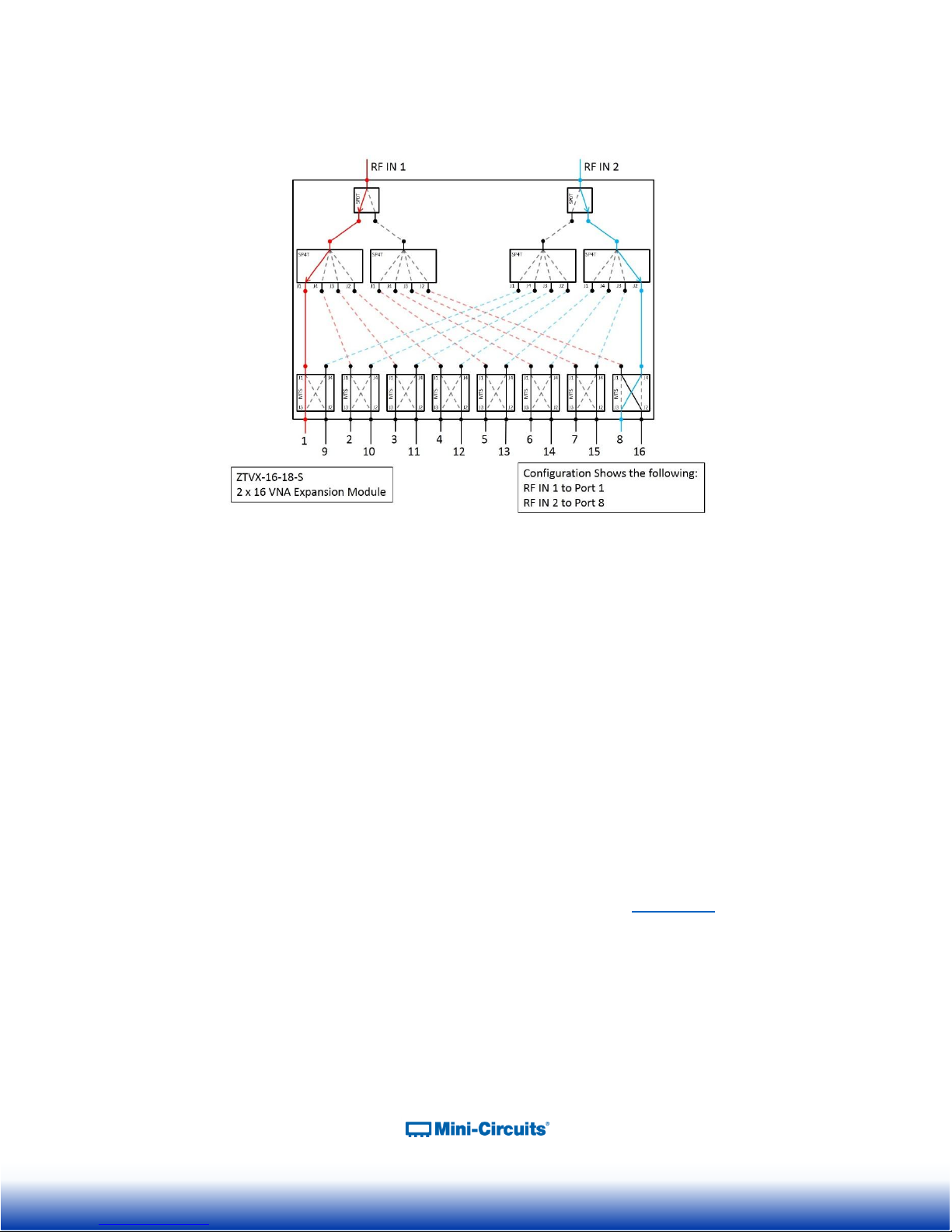
4 FUNCTIONAL DESCRIPTION
Figure 5: ZTVX-unit functional block diagram. 2 x 16 port, DC–18 GHz configuration shown.
Mini-Circuits’ ZTVX-Series 2 x N switch matrices are capable of routing signal from two input
ports (A1 and A2) to any of up to 16 output channels (N1 – N16) through a network of low-loss,
high-isolation electromechanical switches. Models are available with various output port counts
and frequency ranges of DC to either 12 GHz or 18 GHz to meet your needs. The switches in
the system are bidirectional, and all ports may be used as inputs or outputs as needed. This
capability allows easy management of complex signal traffic in test environments. ZTVX
systems have proved particularly useful for testing of multiple DUTs in parallel as well is testing
of DUTs with higher port counts without repeatedly disconnecting and reconnecting test cables,
significantly reducing test time and increasing throughput.
This equipment operates on a 90 to 260V; 47 to 63 Hz AC line supply. The unit contains MiniCircuits’ patented absorptive electromechanical switches with extra-long switching life,
performance qualified to 100 million switch cycles with proper maintenance. The firmware for
the equipment includes a switch cycle counting function, allowing you to monitor the number of
switch cycles elapsed on each switch in the system and alerting you when routine maintenance
is required - every 10 million cycles per switch. See application note AN-83-001 for additional
information on switch life and maintenance.
The equipment may be controlled via USB or Ethernet (HTTP and Telnet Protocols)
connections, allowing setup flexibility and easy remote test management. All units come
supplied with Mini-Circuits’ user-friendly Graphical User Interface (GUI) program and DLLs for
32-bit and 64-bit Windows® operating systems. Full programming support is provided for a wide
range of programming environments on both Windows and Linux® operating systems,
supporting control through your native test software.
8
Page 9
5 UNPACKING
1
2
3
4
5
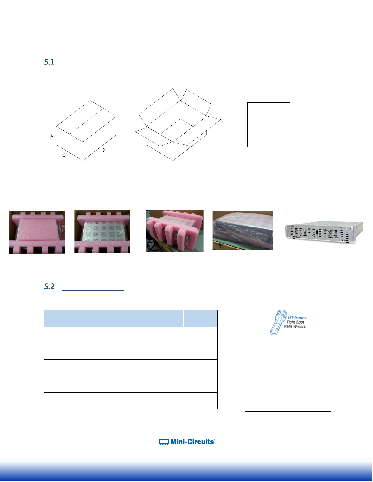
Item Description
Quantity
ZTVX-Series Switch Matrix Assembly
1
CBL-3W-US Black 3-prong AC Cord (7.5 ft.)
1
USB-CBL-AB-7+ USB Cable (6.8 ft.)
1
CBL-RJ45-MM-5+ RJ45 Cable (5 ft.)
1
HT-4-SMA SMA Cable Wrench*
1
A: 7.5”
B: 25.125”
C: 23”
*We’ve included the SMA
connector wrench as a gift
just to make your life easier.
This tool simplifies and
expedites removal and
tightening of cable
connectors in crowded port
configurations.
Unpacking Process
The equipment ships in a single large cardboard carton measuring 7.5 x 25.125 x 23” pictured in
the figure below.
Figure 5: Shipping carton
Within the carton, the ZTVX unit is protected by pink foam inserts on the top and bottom, front
and back, and a pink anti-static bag. The unit can be unpacked following the steps pictured
below.
Package Contents
Table 1: Package Contents
9
Page 10
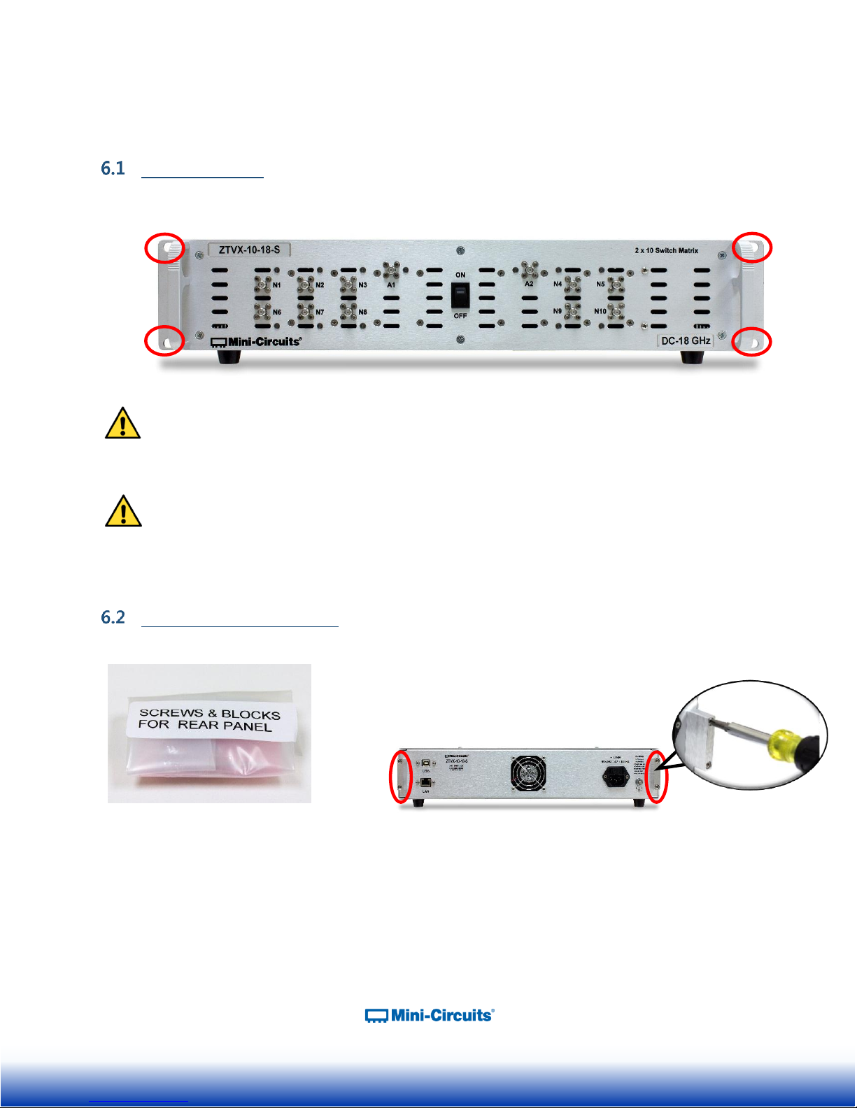
6 LAYOUT AND INSTALLATION
Figure 6: Safety Blocks come in a
clearly labeled plastic bag
Figure 5: Install as shown using a Phillips head screwdriver
Rack Mounting
ZTVX-unit should be fastened to rack support structure through the slotted rack mounting holes
(4x) on the front panel of each box.
Figure 6: Slotted rack mounting holes in front panel of ZTVX-UNIT box.
ZTVX-unit must be mounted to maintain minimum of 1U (1.75”) clearance above top
panel and below bottom panel with unobstructed access to room ambient airflow for proper
operation.
Additionally, due to weight, box must be supported by means other than the front panel.
This can be facilitated by side rails or by a shelf, sufficiently secured to a standard, high grade,
19 inch equipment rack.
Rear Panel Safety Blocks
10
Page 11
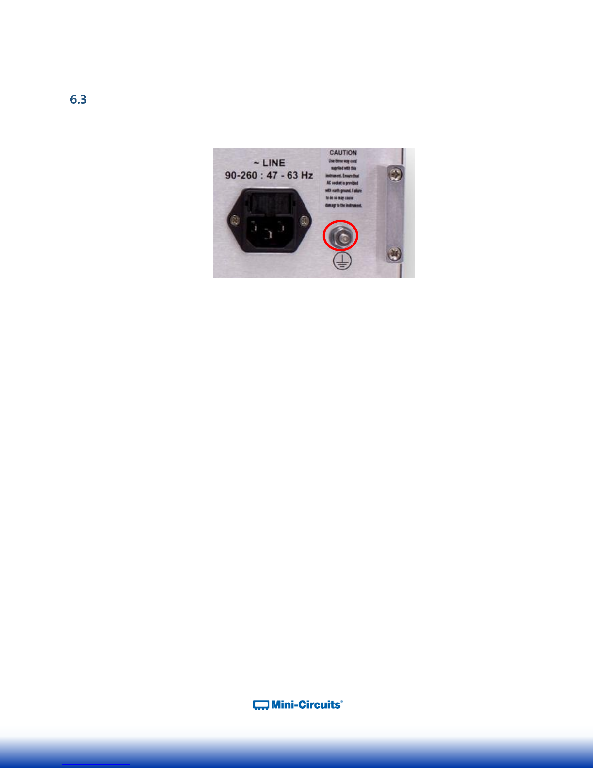
Rear Panel Grounding Stud
The rear panel of the ZTVX-unit is constructed with a #10-32 x ½” long grounding stud to ground
the box.
Figure 7: Rear Panel Grounding Stud
11
Page 12

7 SOFTWARE
Software Overview
The Mini-Circuits ZTVX-unit is supplied with easy-to-install, user-friendly GUI software to control
the unit and manage signal paths in your test setup. If you prefer to create your own program
through your native test software, a full set of DLLs for 32- and 64-bit Windows® and Linux®
programming environments is also included.
This section will acquaint you with the features of the ZTVX GUI user interface. For
programming support and additional information on writing your own test programs for this
equipment, please reach out to the contacts provided on page 4.
Installing the GUI Software
1) Save all work and close any other open applications.
2) Download the latest version of the GUI software, unzip to your PC, and run the setup
program.
Figure 8: Installing ZTVX-UNIT GUI software
3) The software license agreement will appear. Review the agreement, select “I agree,”
and click “Continue.”
Figure 9: Software License Agreement
12
Page 13

4) Be sure all open work in other applications has been saved and closed. Click “OK” to
proceed.
Figure 10: Close Other Applications
5) The Destination Directory Window will appear. This allows you to specify where the GUI
software will be saved on your computer’s hard drive. At this point, it’s a good idea to
take a second and confirm the full destination address for the software. The default
destination directory will be shown here. Change it if you prefer by clicking “Change
Directory”, and be sure record the full destination address for your records. Then click
the large button at the top-left to continue.
Figure 11: Directory Selection Window
13
Page 14

6) The Program Group window will pop up. The Program Group window allows you to
select the program group under which the link for the signal generator GUI program in
the Start Menu will be created. If you change the Program Group for this software, be
sure to record that information together with your destination address for your own
reference. Click on “Continue” to proceed.
Figure 12: Program Group Window
7) An “Installation Complete” message will appear once the software is successfully
installed. Click “OK” to close the installer.
14
Page 15

Using the ZTVX GUI
After you’ve installed the software and opened the program on your PC, the ZTVX GUI main
screen will appear. The ZTVX GUI main screen displays features and controls that allow you to
easily manage the various signal paths and send commands to individual switches in the unit.
Figure 13: ZTVX GUI Main Screen
7.3.1 Connecting to the ZTVX
Once the GUI program is open, you should first establish a connection with the ZTVX
using USB or Ethernet. The software also provides an option to explore the GUI in
“Demo Mode,” without actually connecting to the unit. The controls to connect to the unit
are located at the top of the GUI main screen:
Figure 14: Connection status display and controls
15
Page 16

A. Connecting via USB
1) Make sure the ZTVX unit is connected to your PC via the supplied USB cable and
the power is turned ON.
2) In the GUI main screen, open the drop-down in the “Serial Number” field. Options
should appear displaying the serial number of the unit with different connection
options. Select the option displaying the serial number of the unit with the suffix
“-USB”.
Figure 15: Drop-down with connection options - USB
3) When connected to the ZTVX via USB, the “Protocol” field will read “USB”, and the
“Connection Status” field will read “Connected”.
Figure 16: Displaying active connection to ZTVX via USB
B. Connecting via Ethernet
1) Managing IP Settings:
To connect to the ZTVX via Ethernet-TCP/IP, first connect to the unit via USB as
described above in the Connecting via USB section to configure the IP settings for the
unit.
NOTE: The ZTVX must be connected via USB to set manage IP settings.
Clicking from the GUI main screen opens the Ethernet Configuration
Window:
16
Page 17

Figure 17: Ethernet Configuration Window
The Ethernet Configuration Window enables the user to control the following IP settings:
Use DHCP (Dynamic IP) – Checking this box enables Dynamic Host Control Protocol,
which will cause the ZTVX to derive the IP address, network gateway, and subnet mask
settings automatically from the server to which it is connected. Unchecking this box
disables the automatic mode so that the IP parameters can be set manually.
IP Address: this (Internet Protocol) address allows other devices (such as computers) to
communicate with the ZTVX over an Ethernet Network.
Subnet Mask: this parameter tells the ZTVX which part of its address it can share with
other devices in the same network.
Network Gateway: This parameter represents the address of the network server.
MAC Address: This address is constant and cannot be changed. It identifies the ZTVX’s
physical address for the network server.
TCP/IP port: This parameter represents a port for communicating with the ZTVX using
HTTP or Telnet protocols. The default port for HTTP protocol is 80; the default port for
Telnet protocol is 23.
Use Password: Checking this box implements a password requirement to connect to the
ZTVX via Ethernet. Enter your desired password in the field below, and record it for your
own reference.
NOTE: IF YOU LOSE YOUR PASSWORD, YOU CAN RECOVER IT BY CONNECTING
TO THE ZTVX BY USB AND OPENING THE ETHERNET CONFIGURATION WINDOW.
17
Page 18

2) Establishing a Connection:
Once your IP settings are set as desired, return to the GUI main screen and open the
drop-down in the “Serial Number” field. Select the option that displays the serial
number of your unit and the suffix “-IP”.
Figure 18: Drop-down with connection options – IP
Selecting the IP connection option will open the Ethernet Configuration prompt
shown below:
Figure 19: Ethernet Configuration prompt
You should see the serial number of your unit, IP address and the TCP/IP port
number from Ethernet Settings displayed in their respective fields. The default
TCP/IP port is 80. You should not have to change the entries in these fields.
If you selected “Use Password” in your Ethernet settings, enter your password in the
“Password” field. You then have the option to communicate with the ZTVX using
HTTP or Telnet protocols. Select the protocol you wish to use and click “Connect.”
Once the connection is established, the protocol field will read “IP” with the
appropriate communication protocol (HTTP or Telnet) selected, the IP address of the
unit will be displayed in the “IP” field, and the “Connection Status” field will read
“Connected”.
18
Page 19

Figure 20: Displaying active connection to the ZTVX via Ethernet (HTTP protocol shown)
3) Firewall Access:
If your computer firewall is enabled, you may receive an alert message saying that
Windows Firewall has blocked some features of the program. If this occurs, choose the
networks you want to allow the ZTVX GUI to communicate with, and click “Allow
Access.”
Figure 21: Firewall Alert Message
19
Page 20

C) Demo Mode
Running the GUI in Demo Mode allows the user to explore most GUI features for
demonstration without actually connecting to the ZTVX unit. To explore the ZTVX GUI in
demo mode, select “Demo Mode” from the drop-down in the Serial Number field.
Figure 22: Drop-down with connection options – Demo Mode
The Connection Status field should then display that Demo Mode is active.
Figure 23: Connection Status indicating the ZTVX GUI is running in Demo Mode
7.3.2 GUI Displays and Built-In Reference
The ZTVX GUI main screen features several information displays and built-in references for
your convenience. These are described below:
Configuration File: This field displays the current configuration file loaded in the GUI.
Figure 24: Configuration File
Command History: This field logs a history of commands sent to the ZTVX descending
from oldest to most recent with time and date stamps. Clicking the button clears all
entries in the Command History field.
Figure 25: Command History
20
Page 21

Switch Status and Temperature / Fans Status Display: The Switch Status field shows the
current state of every switch in the ZTVX and the count of elapsed switch cycles on each
switch. The Temperature / Fans Status display shows the status of the unit temperature
and internal cooling fans.
NOTE: When any switch in the system is due for calibration, the counter in the Switch
Status Display will turn red to alert you that it’s time for a tune-up.
Figure 26: Switch Status display and Temperature / Fans Status display
Connection Status: The Connection Status display shows the current active signal path
from A1 and A2 to the corresponding activated “N” ports.
Figure 27: Connection Status display
21
Page 22

Block Diagram: Clicking the button opens the ZTVX block diagram in a
separate window for your reference.
Figure 28: Block Diagram display (2 x 8 configuration shown)
Help File: Clicking the opens the Read Me file for the ZTVX which
contains information about communicating with the ZTVX via HTTP and Telnet protocols
as well as a complete list of the command structures with definitions for each.
The Help File also contains a button which links to a PDF of the most
recent version of this user manual. Whenever changes are made to the ZTVX software
or other features of the equipment, you can find updates to the user guide by clicking this
button.
: Modify Buttons opens the Modify Buttons Menu to save a variety of
functions to the Quick Set Buttons. This feature is discussed below in section 8.3.3
(A)(1).
: The GUI will automatically load the factory-setting configuration file for
the connected ZTVX unit (see section 7.3.3). The Load Config button opens the
destination directory for all additional saved configuration files. From here you can load
custom settings you’ve saved as desired. Configuration files are discussed further in
section 7.3.3 (B)(2).
: The Clear All button resets the Switches to their default states.
22
Page 23

7.3.3 Sending Commands
The ZTVX GUI main control provides a full toolbox of controls for you to manage signal
paths or send commands to individual components in the system. These controls are
separated into 3 groups as follows:
A) Set Path
B) Quick Set Buttons
C) Manual Commands
Each of these groups is discussed in detail in the sections below.
A) Set Path
Figure 29: Set Path controls
The “Set Path” controls allow you to specify any signal path in the ZTVX system by
selecting from drop-down menus specifying desired signal input (“From”) and signal
output (“To”).
Other related functions include:
Show Command: This button will display the specific command string corresponding to
your signal path selection in the “From” and “To” drop-downs. The command string will
appear in the “Command” field of the Manual Commands panel near the bottom of the
GUI main screen.
Figure 30: Clicking the Show Command button displays the specific command string corresponding to a
given path selection.
23
Page 24

Save to Quick Set Button: This button saves the current selected path from the Set Path
panel to any Quick Set Button of your choice. Choose the button you wish to save the
selected path to from the drop down menu. That button will then be renamed with the
syntax (From)>(To). Also see the section on Quick Set Buttons for more information.
Figure 31: Save to Quick Set Buttons opens a drop-down allowing you to choose a button to save
the current selected path to.
Send: This button activates the selected signal path. Commands will not be sent to the ZTVX
until you click “Send”.
B) Quick Set Buttons
Figure 32: Quick-Set Buttons control panel with factory settings automatically loaded.
Quick-Set Buttons enable easy, one-click activation of any signal path or individual
switch command specified by the user. Buttons are organized into 5 tabs, each with 20
buttons for up to 100 pre-defined functions for quick activation. Quick-Set Buttons send
commands to the ZTVX immediately once you click a button.
This feature also allows you to rename tabs and buttons as well as to save all your
settings as a configuration file to load and reuse in future tests.
The GUI will automatically load the factory settings configuration file for your ZTVX unit
when connected to the hardware. The factory settings include a quick-set button for
each signal path in your system as shown in Figure 32. The first tab displays buttons for
all paths from port A1 to each of the N-ports. The second tab displays buttons for all
paths from port A2 to each of the N-ports.
24
Page 25

1. Modifying Quick-Set Buttons
a. To save a command to a Quick-Set Button, you can select a path in the Set Path
control and use the “Save to Quick-Set Buttons” feature described above in the
section on
b. For more options to configure Quick-Set Buttons, click . The Modify
Buttons Menu will appear:
Figure 33: Modify Buttons Menu
The Modify Buttons Menu allows you to save signal paths and individual commands to
all Quick Set Buttons as desired. It also provides options to rename buttons, rename
tabs, and save your settings as configuration files for later use.
To modify a button, first click the button you wish to modify in the Modify Buttons Menu:
Figure 34: First click the button you wish to modify.
25
Page 26

From here you can modify the selected button with the options in the Set Button Action
panel:
Figure 35: Set Button Action options
The Set Button Action panel includes the following options:
Tab Name: To rename a tab, click on the tab of interest and type the desired name in the
“Tab Name” field. Then click the button at the bottom of the screen to save
settings. The new name should then appear on the selected tab.
Button Name: To rename a button, enter a name for the selected button in this field and
save settings. The selected button will then display the new name.
Set Switch: Selecting the Set Switch radio button allows you to select a specific switch in
the ZTVX from the drop menu. Clicking a button assigned to a given switch will tell that
switch to cycle through switch states sequentially.
Choose Switch: This drop menu allows you to choose the switch to assign to the
selected Quick-Set Button. Note that the button naming function is inactive when
assigning a button to a single switch. The button will automatically be named according
to its assigned switch. Refer to the ZTVX block diagram to locate individual switch
numbers in the system.
Figure 36: Choose Switch drop menu
26
Page 27

Send Manual Command: Clicking the Send Manual Command radio button activates
options to build a command for the selected button. You can assign commands to the
button in one of two ways:
All Commands: This drop menu contains a full list of commands for components
and signal paths in the ZTVX. Selecting a command will add that command to
the string in the Command Display field. Some users may find this feature easier
than manually typing out commands.
From / To Drop-Downs: These menus allow you to define a signal path by
selecting options from the “From” and “To” drop-down menus. The
corresponding command string will appear in the Command Display Field.
: Click this button to add a specified command to the Command Display field.
Command Display Field: This field allows you to manually enter any string of commands
to control any component or signal path in the ZTVX. Commands in a string must be
separated by a semicolon. You may type commands yourself or add commands from
the All Commands and Paths drop menus below.
Figure 37: Command Display Field
Click to save the command string to the selected button.
: This check box allows you to choose
whether the command string for the selected button should be automatically preceded by
the “ClearAll” command.
27
Page 28

2. Configuration Files
The ZTVX GUI allows you to save all Quick-Set Buttons from a particular application as
a .txt “configuration file.” Configuration files can then be easily retrieved for repeated
use, saving setup time for tests regularly performed using the ZTVX.
To create a new configuration file, first make sure all Quick-Set Buttons are configured as
needed for your test application. Then, open the Modify Buttons Menu and click the
button. The “Save Configuration” prompt will pop up:
Figure 38: “Save Configuration” prompt
Name the file something easy to remember and click O.K. The configuration file
is now saved. The default location for configuration files is:
C:\Program Files (x86)\Mini-Circuits ZTVX\Config
To load an existing configuration file, simply click and the Load Configuration
File prompt will appear:
Figure 39: Load Configuration File prompt
Select the desired configuration file and click “O.K.” The GUI will then display the settings
last saved in the chosen configuration file.
28
Page 29

To modify an existing configuration file, load the configuration file, and open the Modify
Buttons Menu. Make any desired changes to the Quick-Set Buttons, and click the
button. Your changes will then be saved to the current open configuration file.
To exit the Modify Buttons Menu, click the button to return to the main control at
any time. If you have not saved your settings before closing the Modify Buttons menu, you
will be prompted to save your settings before closing.
C) Manual Commands
Figure 40: Manual Commands control panel
The Manual Commands control panel allows you to enter and send individual commands
or strings of commands manually. From the Manual Commands control, you can send
commands to individual components or groups of components in the ZTVX.
Switch Commands: This drop-down provides a full list of commands for individual
switches in the ZTVX. It also includes a full list of “Path=” commands specifying the full
signal path in a single command.
Switch States: This drop-down provides a list of commands that return the current state
of any switch in the ZTVX.
Switch Counters: This drop-down provides a list of commands that return the count of
switch cycles elapsed on each switch in the ZTVX.
Additional Commands: This drop-down provides a list of additional queries and
commands for the ZTVX.
: This button adds the command selected from the dropdown menu to the
Command display.
Command: This field displays the chosen command or string of commands to send to
the ZTVX.
NOTE: Commands in a string must be separated by a semicolon (;).
Send: This button sends the command or command string in the “Command” field to the
ZTVX. Commands will not be executed until the “Send” button is clicked.
29
Page 30

Updating Firmware
Current Version
Caution: interruption of firmware upgrade process (due to USB disconnection, or
power failure) may render the unit unresponsive.
NOTE: The firmware information and upgrade option are only available via the USB
connection.
1) To check your firmware version and update firmware when new versions are available,
click the “Firmware Update” button at the upper right area of the GUI main screen.
Figure 41: Firmware Update Button
2) The Firmware Info Window will appear, displaying the current version of firmware:
Figure 42: Firmware Info Window
3) When firmware updates become available for the ZTVX-UNIT, Mini-Circuits will provide
you with the new firmware for download. Save the new firmware file to a desired location
on your computer or network. Be sure to note the location of the latest firmware file.
30
Page 31

Click to Update
4) Once you’ve downloaded the latest version firmware, you can begin updating by clicking
“Update Firmware” in the firmware info window.
Figure 43: Click “Update Firmware” to initiate the update process.
5) The Firmware Browse Window will appear. Select the firmware file from the location
where you saved it earlier in (3). Then click “O.K.”
Figure 44: Firmware Browse Window
A status indicator will appear on screen and advise when the update is complete. The ZTVXUNIT will then restart for the new firmware to take effect.
31
Page 32

Programming Support
In addition to the supplied GUI program, you may also create your own control interface
for the ZTVX-UNIT. Mini-Circuits offers support for a variety of operating systems,
programming environments, and third party applications including (but not limited to):
Visual Basic
Delphi
Borland C++
CVI
®
LabVIEW
MATLAB
Python
Agilent VEE
®
, Visual C#®, Visual C++®
®
®
®
®
®
®
This unit is supplied with DLLs for 32- and 64-bit Windows® systems and complete
programming instructions for Windows and Linux® environments. If you have any
questions or require additional programming support at any time, please feel free to get in
touch with us using the contact information on page 4.
32
Page 33

8 RETURN MATERIAL AUTHORIZATION (RMA)
PROCEDURE
If you have received this unit by mistake or wish to return it for evaluation, please reach out to
the support contacts listed on page 4. For your convenience, you may also contact our Sales
Department at (718) 934-4500 / sales@minicircuits.com or your local Mini-Circuits sales
representative. They will review your RMA request, and per Mini-Circuits RMA policy, issue an
identification number to ensure proper handling. All returns must be accompanied by
appropriate Mini-Circuits identification and documentation to ensure proper handling.
33
Page 34

9 APPENDIX: ELECTRICAL SCHEMATICS
ZTVX-8-12
2 x 8 port, DC – 12 GHz configuration
ZTVX-10-12
2 x 10 port, DC – 12 GHz configuration
ZTVX-12-12
2 x 12 port, DC – 12 GHz configuration
ZTVX-16-12
2 x 16 port, DC – 12 GHz configuration
34
Page 35

ZTVX-8-18
2 x 8 port, DC – 18 GHz configuration
ZTVX-10-18
2 x 10 port, DC – 18 GHz configuration
ZTVX-12-18
2 x 12 port, DC – 18 GHz configuration
ZTVX-16-18
2 x 16 port, DC – 18 GHz configuration
35
 Loading...