

Mini-Circuits RC-3SPDT-A18, USB-2SPDT-A18, USB-4SPDT-A18, RC-2SPDT-A18, RC-4SPDT-A18 User Manual
...Page 1
User Guide
USB/Ethernet RF Switch Matrices
USB-1SPDT-A18 / RC-1SPDT-A18
DC to 18 GHz
Single SPDT switch
USB-2SPDT-A18 / RC-2SPDT-A18
DC to 18 GHz
Two SPDT switches,
USB-3SPDT-A18 / RC-3SPDT-A18
DC to 18 GHz
Three SPDT switches,
Configurable as: SPDT, DPDT, 3PDT, SP3T,
USB-4SPDT-A18 / RC-4SPDT-A18
DC to 18 GHz
Four SPDT switches,
Configurable as: SPDT, 4PDT, SP3T, SP5T,
USB-8SPDT-A18 / RC-8SPDT-A18
DC to 18 GHz
Eight SPDT switches,
Configurable as: SPDT, SP3T, SP8T, 2x8, dual
USB-1SP4T-A18 / RC-1SP4T-A18
DC to 18 GHz
Single SP4T switch
Transfer switch and more
AN-49-002 Rev.: A (November 25, 2014) M149081 (R88277) File: AN-49-002(A).doc
This document and its contents are the property of Mini-Circuits
Page 2

Important Notice
This guide is owned by Mini-Circuits and is protected by copyright, trademark
and other intellectual property laws.
The information in this guide is provided by Mini-Circuits as an accommodation
to our customers and may be used only to promote and accompany the
purchase of Mini-Circuits’ Parts. This guide may not be reproduced, modified,
distributed, published, stored in an electronic database, or transmitted and the
information contained herein may not be exploited in any form or by any means,
electronic, mechanical recording or otherwise, without prior written permission
from Mini-Circuits.
This guide is subject to change, qualifications, variations, adjustments or
modifications without notice and may contain errors, omissions, inaccuracies,
mistakes or deficiencies. Mini-Circuits assumes no responsibility for, and will
have no liability on account of, any of the foregoing. Accordingly, this guide
should be used as a guideline only.
Trademarks
Microsoft, Windows, Visual Basic, Visual C# and Visual C++ are registered
trademarks of Microsoft Corporation. LabVIEW and CVI are registered
trademarks of National Instruments Corporation. Delphi is a registered
trademark of Delphi Technologies, Inc. MATLAB is a registered trademark of
The MathWorks, Inc. Agilent VEE is a registered trademark of Agilent
Technologies, Inc. Linux is a registered trademark of Linus Torvalds. Mac is a
registered trademark of Apple Inc. Python is a registered trademark of Python
Software Foundation Corporation.
All other trademarks cited within this guide are the property of their respective
owners. Neither Mini-Circuits nor the Mini-Circuits switch matrices are affiliated
with or endorsed or sponsored by the owners of the above referenced
trademarks.
Mini-Circuits and the Mini-Circuits logo are registered trademarks of Scientific
Components Corporation.
Mini-Circuits
13 Neptune Avenue
Brooklyn, NY 11235, USA
Phone: +1-718-934-4500
Email: sales@minicircuits.com
Web: www.minicircuits.com
AN-49-001 Rev.: A (November 25, 2014) M149081 (R88277) File: AN-49-002(A).doc
This document and its contents are the property of Mini-Circuits
Page 2 of 33
Page 3

Table of Contents
Chapter 1 – General Information.........................................................5-8
1.1 Scope of the User Guide..................................................................................... 5
1.2 Warranty ............................................................................................................. 5
1.3 Definitions ........................................................................................................... 5
1.4 General safety precautions ................................................................................. 5
1.5 Introduction ......................................................................................................... 5
1.6 Service and Calibration ....................................................................................... 6
1.7 Contact Information............................................................................................. 6
1.8 Technical description ....................................................................................... 6-8
1.8.1 Features of Mini-Circuits Switch Matrices ..................................................................6
1.8.2 Intended Applications.................................................................................................7
1.8.3 Conformity..................................................................................................................7
1.8.4 Supported Software environments.............................................................................7
1.8.5 Included Accessories and Options.............................................................................8
Chapter 2 – Installation and Setup ....................................................9-14
2.1 Software Setup ................................................................................................... 9
2.2 Installation.................................................................................................... 10-11
2.3 USB/Ethernet Switch Matrix Physical Setup ................................................ 12-14
2.4 Controlling the Mini-Circuits Switch Matrix .........................................................14
Chapter 3 – Using Mini-Circuits' Switch Matrix.............................15-33
3.1 USB interface............................................................................................... 15-17
3.2 Ethernet Interface......................................................................................... 17-20
3.3 Switch Configurations .................................................................................. 20-27
3.3.1 USB-1SPDT-A18 / RC-1SPDT-A18 ........................................................................20
3.3.2 USB-2SPDT-A18 / RC-2SPDT-A18.................................................................. 21-20
3.3.3 USB-3SPDT-A18 / RC-3SPDT-A18.................................................................. 23-22
3.3.4 USB-4SPDT-A18 / RC-4SPDT-A18.................................................................. 24-24
3.3.5 USB-8SPDT-A18 / RC-8SPDT-A18 ........................................................................26
AN-49-001 Rev.: A (November 25, 2014) M149081 (R88277) File: AN-49-002(A).doc
This document and its contents are the property of Mini-Circuits
Page 3 of 33
Page 4
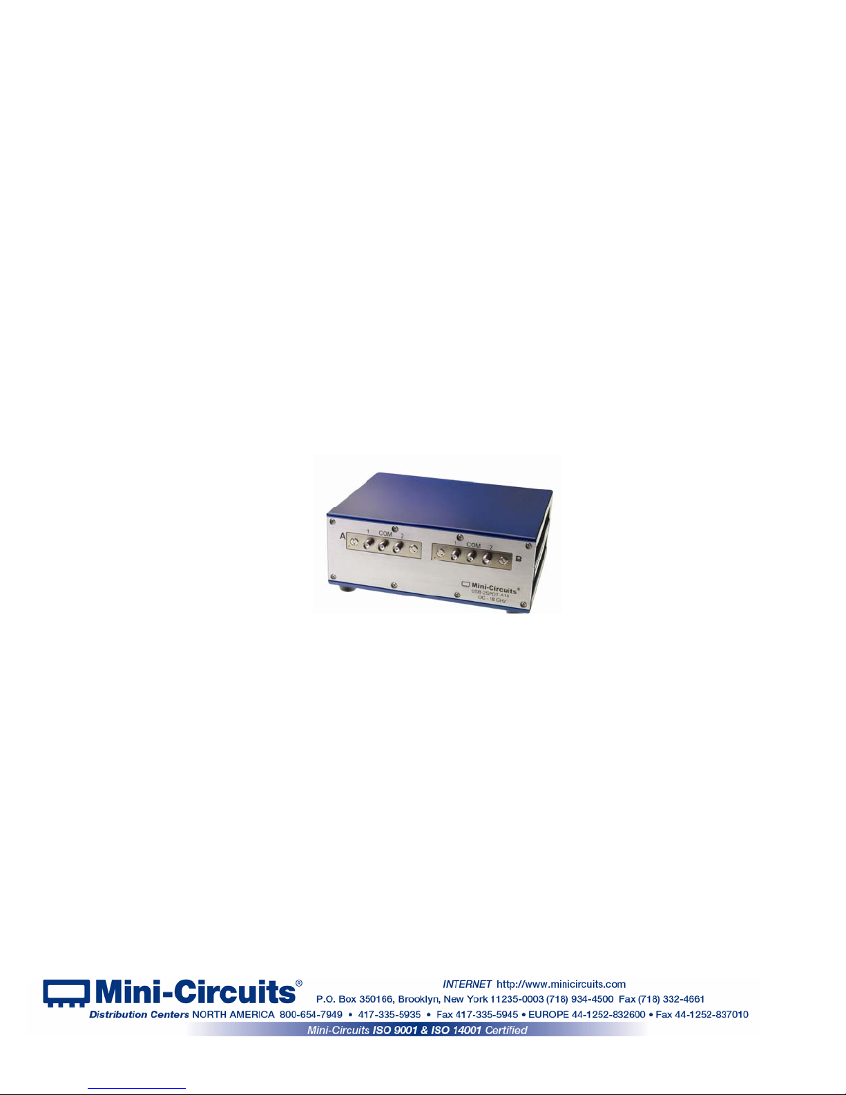
Table of Contents
3.3.6 USB-1SP4T-A18 / RC-1SP4T-A18 ..........................................................................27
3.3.7 Additional configurations, not shown here ...............................................................27
3.4 User Sequence ............................................................................................ 28-30
3.4.1 User sequence screen buttons and indicators ................................................... 28-29
3.4.2 User sequence graphical switch presentation.................................................... 29-30
3.5 Firmware update .......................................................................................... 31-32
3.6 Demo Mode .......................................................................................................33
Figure 1: MINI-CIRCUITS USB RF SPDT Switch
AN-49-001 Rev.: A (November 25, 2014) M149081 (R88277) File: AN-49-002(A).doc
This document and its contents are the property of Mini-Circuits
Page 4 of 33
Page 5
1 Chapter 1 – General Information
1.1 Scope of the User Guide
This user guide provides general introduction, installation instructions and operating information
for Mini-Circuits USB and Ethernet control RF switch matrices.
1.2 Warranty
See Mini-Circuits website http://www.minicircuits.com/support/ordering.html for warranty
information.
1.3 Definitions
Note: A note advises on important information you may need to ensure proper operation of the equipment.
There is no risk to either the equipment or the user.
CAUTION
A caution advises about a condition or procedure which can cause damage to the
equipment (no danger to users).
WARNING
A warning al
until you are sure you understand the warning.
1.4 General safety precautions
WARNING
CAUTION
Ensure that all instruments using mains power supply are properly grounded to
prevent risk of electrical shock.
1. Ensure th
2. Do not a
1.5 Introduction
Mini-Circuits has developed two series of RF switch matrices, the RC-xxxxx-A18 series capable
of USB and Ethernet (HTTP and Telnet protocols) control and the USB-xxxxx-A18 series with
just USB control. Both series have SPDT and SP4T switches, like the one shown in Figure 1.
These switches operate from DC to 18 GHz; all are available in a variety of different
configurations with low insertion loss (0.2 dB typ.) and high isolation (85 dB typ). All models are
USB HID devices and are “plug & play,” with no driver installation needed. Ethernet control in
the RC-xxxxx-A18 series allows for both dynamic (DHCP) and static IP. Using the supplied GUI
software or most common lab test software you can easily set complex, timed switching
sequences using multiple switches with only a single power supply and USB control line, or
Ethernet. You can even synchronize other software with the switching sequence. These
USB/Ethernet RF switches are light, compact and greatly simplify setting up complex switching
sequences.
Using the Ethernet interface the switch matrices can be controlled from any computer with an
internet connection, or even your smartphone from almost anywhere!
erts to a possible risk to the user and steps to avoid it. DO NOT
proceed
Please observe the following safety precautions at all times when using Mini-Circuits USB
RF switch matrices.
e switch matrix air vents are clear
ttempt to switch signals of greater power than the switch is rated for in its
datasheet.
AN-49-001 Rev.: A (November 25, 2014) M149081 (R88277) File: AN-49-002(A).doc
This document and its contents are the property of Mini-Circuits
Page 5 of 33
Page 6

1.6 Service and Calibration
The USB/Ethernet switch matrix models do not require any periodic service or calibration. The
only user service possible for the switch matrix models is external cleaning of the case and
connectors as needed. Do not use any detergents or spray cleaning solutions to clean the
Switch Matrix. To clean the connectors use an alcohol solution, and to clean the case a soft,
damp cloth.
1.7 Contact Information
Mini-Circuits inc.
13 Neptune Ave
Brooklyn, NY 11235
Phone: 1-718-934-4500
General Fax: 1-718-332-4661
Sales / Customer Service Fax: 1-718-934-7092
sales@minicircuits.com
For regional offices and tech support see http://www.minicircuits.com/contact/offices.html
1.8 Technical description
1.8.1 Features of Mini-Circuits Switch Matrices
• Capable of 100 million switching cycles
• DC to 18GHz; absorptive failsafe RF switches in break-before-make configuration
• Electromechanical switching; Isolation 85 dB typ.
• High power handling, 10W SPDT, 2W SP4T
• All RF ports SMA(F)
• Easy GUI installation and operation, simplifies complex switching and timing setups
• USB HID ”plug & play” device
• For RC-xxxxx-A18 series Telnet and HTTP ”plug & play” device
®
• ActiveX com object and .Net class library for use with other software: C++, C#, CVI
8 or newer, MATLAB
more
• User friendly Graphical User Interface for any Windows
®
computers
Linux
• For RC-xxxxx-A18 series command line support for any computer with a network connection (HTTP &
Telnet protocols)
power adapter included
• 24V
DC
• Protected by US Patents 5,272,458; 6,414,577; 6,650,210; 7,633,361 and 7,843,289
®
7 or newer, Python, Agilent VEE®, Visual Basic®, Visual Studio® 6 or newer, and
®
32 or 64 bit computer. command line support for
, Delphi®, LabVIEW®
For specific model features, performance data and graphs, outline drawing, ordering information
and environmental specifications, see our catalog at:
http://www.minicircuits.com/products/u
Page 6 of 33
AN-49-001 Rev.: A (November 25, 2014) M149081 (R88277) File: AN-49-002(A).doc
This document and its contents are the property of Mini-Circuits
sb_rfspdt_switches.shtml
Page 7

1.8.2 Intended Applications
Mini-Circuits USB-xxxxx-A18 and RC-xxxxx-A18 series switch matrices are intended for indoor
use in:
- Lab and test equipment setups for both manual and automated measurements
- Control systems
- Automated switching of signal paths in a complex system
The models can be used by anyone familiar with the basics of electronics measurements or
electronic control systems.
1.8.3 Conformity
Mini-Circuits USB-xxxxx-A18 and RC-xxxxx-A18 series switch matrices conform to all
requirements for the following international standards
:
RoHS – The models comply with EU directive for Restriction of Hazardous Substances
for 6 substances.
USB 2.0 – The models meet the specifications of the Universal Serial Bus Ver. 2.0
communication standard as described by USB-IF.
USB HID – The models meet the requirements for Universal Serial Bus Human
Interface Devices according to USB-IF’s Device Class Definition for Human
Interface Devices firmware rev. 1.11.
TCP/IP – The RC-xxxxx-A18 series models’ Ethernet communication complies with the
specifications of the Transmission Control Protocol (TCP) and Internet
Protocol (IP) as defined in RFC 791 and RFC 793.
HTTP – The RC-xxxxx-A18 series models’ supp
ort all requirements for communicating
with the Hypertext Transfer Protocol (HTTP) as defined in RFC 1945.
Telnet – The RC-xxxxx-A18 series models’ support all requirements for communicating
with the Telnet protocol, as defined in RFC 854.
1.8.4 Supported Software environments
Mini-Circuits USB-xxxxx-A18 and RC-xxxxx-A18 series switch matrices have been tested in
the following operating systems:
32 bit systems: Windows 8, Windows 7, Windows Vista, Windows XP Windows 98
64 bit systems: Windows 8, Windows 7, Windows Vista, Linux
The switch matrices will work with almost any software environment that supports ActiveX or
.Net including:
®
VEE
, Visual Basic®, AutoIT, Visual Studio® 6 or newer, and more
C++, C#, CVI®, Delphi®, LabVIEW® 8 or newer, MATLAB® 7 or newer, Python, Agilent
Additionally the HTTP and Telnet protocols can operate from almost any computer with a
network connection.
For more information see Mini-Circuits programming handbook Introduction
and Chapter 2 on
our website.
AN-49-001 Rev.: A (November 25, 2014) M149081 (R88277) File: AN-49-002(A).doc
This document and its contents are the property of Mini-Circuits
Page 7 of 33
Page 8
g
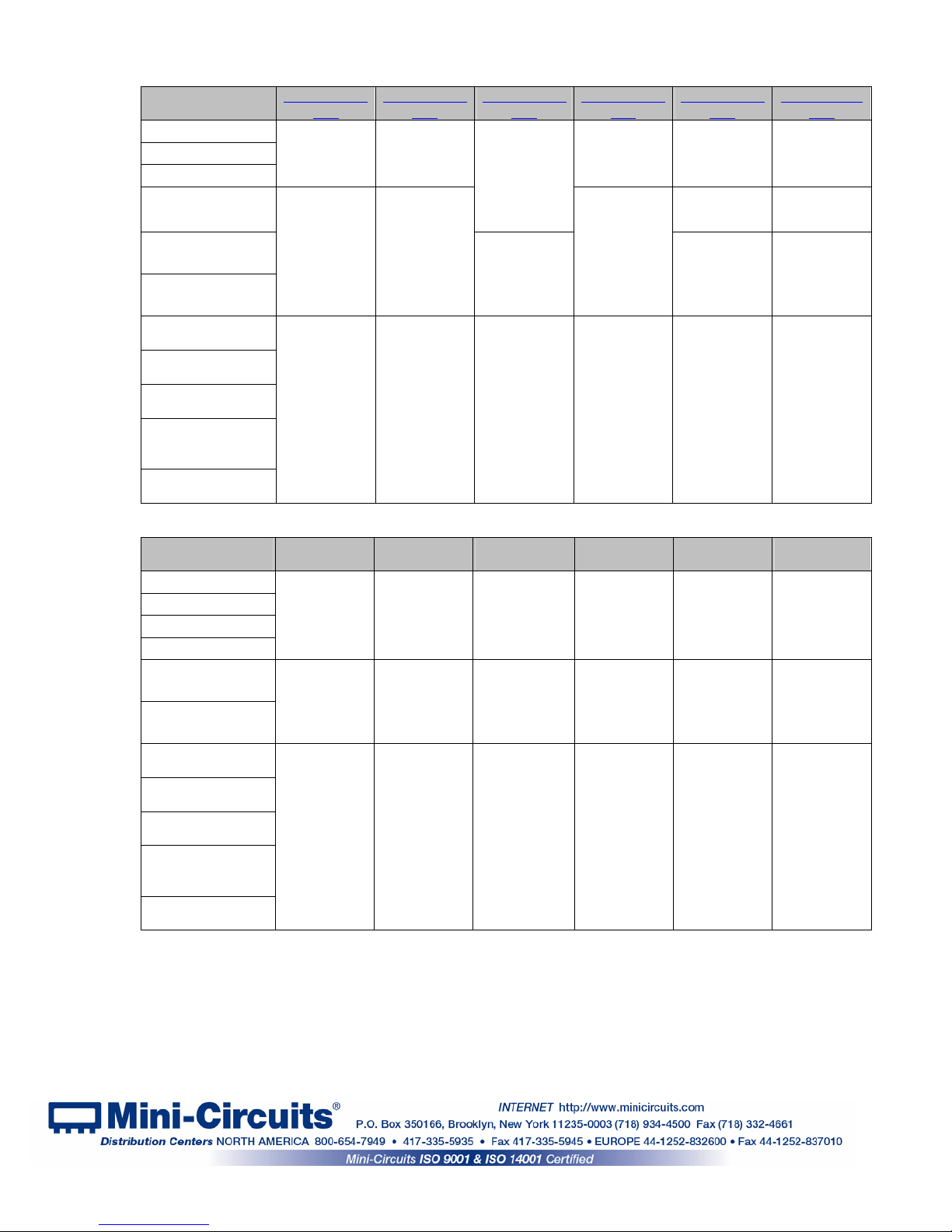
1.8.5 Included Accessories and Options
Accessories
Available
Software CD
2.7 ft. USB cable
24V power adaptor
Hand Flex RF cable
6.8 ft. USB cable
11 ft. USB cable
US standard
power cord
EU standard
power cord
UK standard
power cord
AUS/China
standard
power cord
IL standard
power cord
Accessories
Available
Software CD
2.7 ft. USB cable
5 ft. Ethernet cable
24V power adaptor
6.8 ft. USB cable
11 ft. USB cable
US standard
power cord
EU standard
power cord
UK standard
power cord
AUS/China
standard
power cord
IL standard
power cord
For additional details and ordering information, click on model P/N at the top of the column.
USB-1SPDT-
A18
Included with
the model at
no extra
char
e
Available as
additional
accessories
When ordering
select one
power cord to
be included at
no extra
charge
RC-1SPDT-
A18
Included with
the model at
no extra
charge
Available as
additional
accessories,
see spec. for
details
When ordering
select one
power cord to
be included at
no extra
charge
USB-2SPDT-
A18
Included with
the model at
no extra
charge
Available as
additional
accessories
When ordering
select one
power cord to
be included at
no extra
charge
RC-2SPDT-
A18
Included with
the model at
no extra
charge
Available as
additional
accessories,
see spec. for
details
When ordering
select one
power cord to
be included at
no extra
charge
USB-3SPDT-
A18
Included with
the model at
no extra
charge
Available as
additional
accessories
When ordering
select one
power cord to
be included at
no extra
charge
RC-3SPDT-
A18
Included with
the model at no
extra charge
Available as
additional
accessories,
see spec. for
details
When ordering
select one
power cord to
be included at
no extra charge
USB-4SPDT-
A18
Included with
the model at
no extra
charge
Available as
additional
accessories,
see spec. for
details
When ordering
select one
power cord to
be included at
no extra
charge
RC-4SPDT-
A18
Included with
the model at
no extra
charge
Available as
additional
accessories,
see spec. for
details
When ordering
select one
power cord to
be included at
no extra
charge
USB-8SPDT-
Included with
the model at
no extra
charge
Not available
as accessory
Available as
additional
accessories,
see spec. for
details
When ordering
select one
power cord to
be included at
no extra
charge
RC-8SPDT-
Included with
the model at
no extra
charge
Available as
additional
accessories,
see spec. for
details
When ordering
select one
power cord to
be included at
no extra
charge
A18
A18
USB-1SP4T-
A18
Included with
the model at
no extra
charge
Not available
as accessory
Available as
additional
accessories,
see spec. for
details
When ordering
select one
power cord to
be included at
no extra
charge
RC-1SP4T-
A18
Included with
the model at
no extra
charge
Available as
additional
accessories,
see spec. for
details
When ordering
select one
power cord to
be included at
no extra
charge
AN-49-001 Rev.: A (November 25, 2014) M149081 (R88277) File: AN-49-002(A).doc
This document and its contents are the property of Mini-Circuits
Page 8 of 33
Page 9
2 Chapter 2 – Installation and Setup
System requirements for the switch matrix models are a computer (Pentium II or better) with
either support for USB HID or an Ethernet connection, and a power source of 110-220V
socket matching the plug of the power cord selected when ordering the switch matrix). To run
the GUI program a Windows operating system for either 32 or 64 bits is also required.
2.1 Software Setup
If you have had any problems installing the software, we’re here to help.
Try following these complete step-by-step instructions. If you still experience problems,
give us a call at Mini-Circuits Worldwide Technical support. It’s (718) 934-4500 or e-mail
apps@minicircuits.com
tech_support.html for other regional numbers and addresses.
2.1.1 First save all work in progress and close any other programs that may be running.
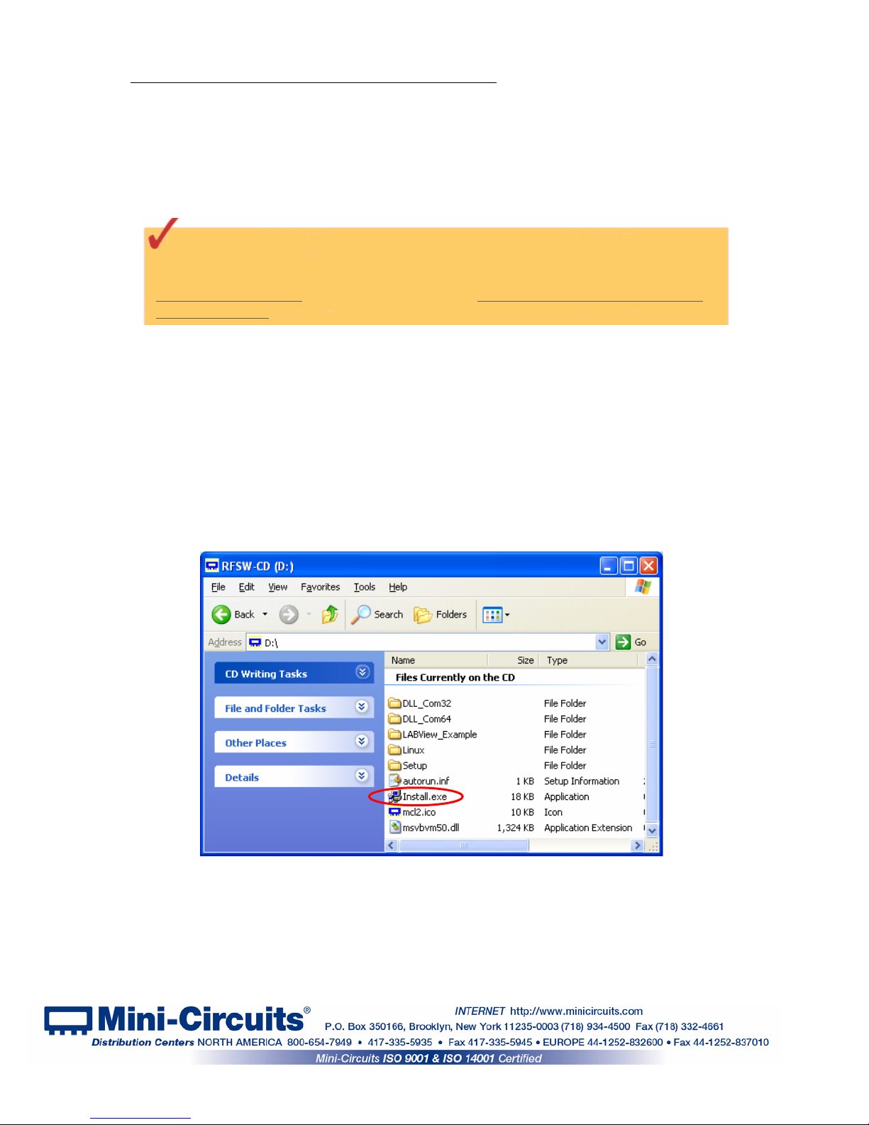
2.1.2 Next, Insert the Mini-Circuits CD into the CD-ROM drive, or download the full CD
software from minicircuits.com. If installing from files downloaded from the web - unzip the
downloaded files to a temporary folder on your desktop or C: drive, then open the file folder
you created and double-click the “Install” icon.
2.1.3 If installation from the CD does not start automatically, run
install.exe from the <CD drive> root directory.
for North America, or go to minicircuits.com/contact/worldwide_
(with
AC
Figure 2.1.3 CD file listing window
AN-49-001 Rev.: A (November 25, 2014) M149081 (R88277) File: AN-49-002(A).doc
This document and its contents are the property of Mini-Circuits
Page 9 of 33
Page 10
2.2 Installation
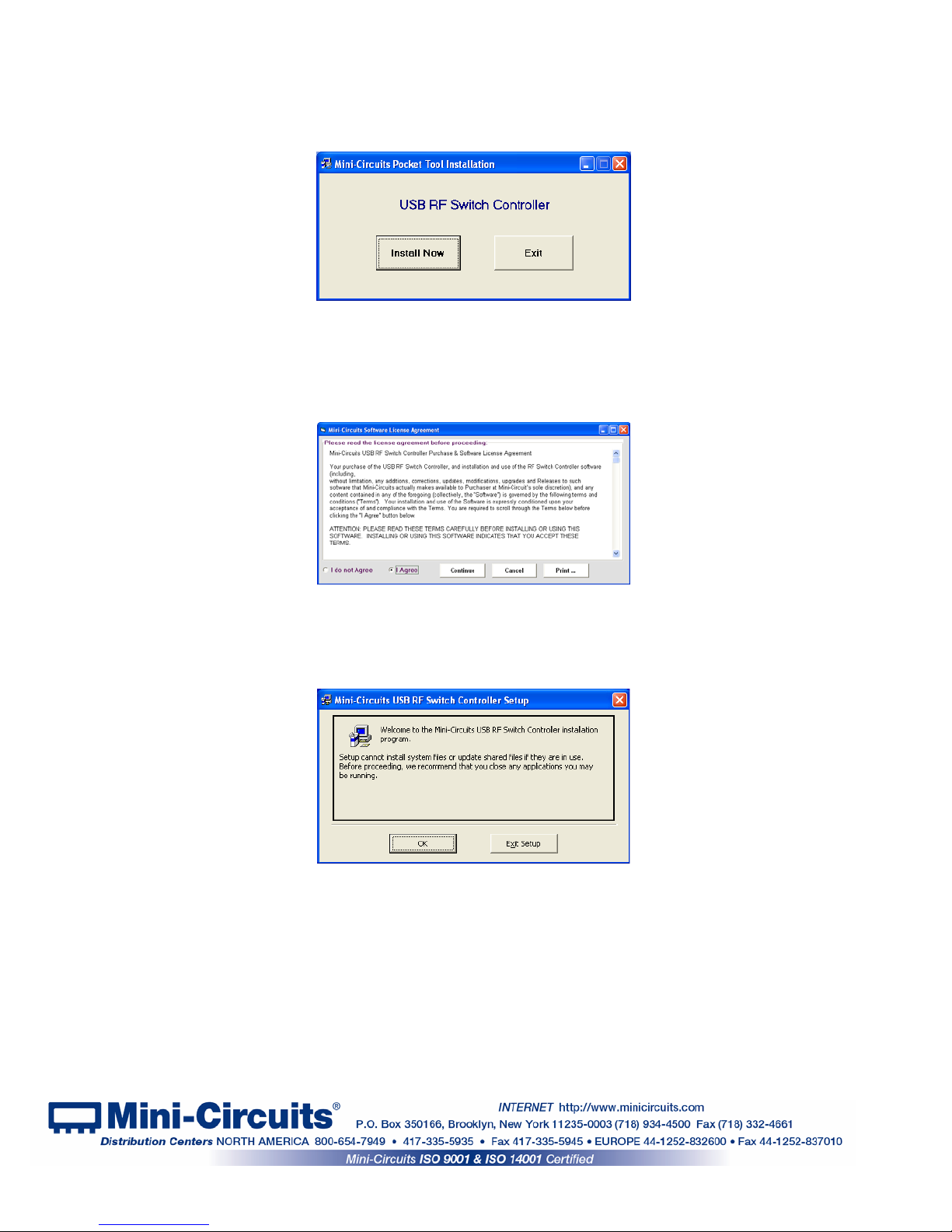
2.2.1 The installer window should now appear. Click the “Install Now” button.
Figure 2.2.1 Installation window
2.2.2 The license agreement should now appear. To proceed, click “I Agree” and
the “Continue” button.
2.2.3 The installation program will launch. Click the “OK” button to continue.
Figure 2.2.2 License agreement
Figure 2.2.3 Installation Program window
AN-49-001 Rev.: A (November 25, 2014) M149081 (R88277) File: AN-49-002(A).doc
This document and its contents are the property of Mini-Circuits
Page 10 of 33
Page 11

2.2.4 The destination directory window will appear. At this point it’s a good idea to
take a second and confirm the full destination address for the software. In most cases, the
default will be your computer’s hard drive (C:)\Program Files\Mini-Circuits RF Switch Box\. Or
Change it then click the large button at the top to continue.
Figure 2.2.4: Destination Directory window
2.2.5 The Program Group window will appear. This window allows you to select the
program group under which the link for the switch controller program in the Start Menu will be
created. If you change the Program Group for this software, be sure to record that information
together with your destination address. Click on “Continue” to proceed.
Figure 2.2.5: Program Group Window
2.2.6 In a second or two, your installation will be complete. Click “OK” to
close the installer.
Figure 2.2.6: Installation complete
AN-49-001 Rev.: A (November 25, 2014) M149081 (R88277) File: AN-49-002(A).doc
This document and its contents are the property of Mini-Circuits
Page 11 of 33
Page 12

2.3 USB/Ethernet Switch Matrix Physical Setup
WARNING
2.3.1 Before connecting the switch matrix, ensure the power switch is in the OFF position
and the control software (either the supplied GUI software or a customer written application) is
shut down.
Ensure the wall socket you use to power the switch matrix is intact and connected to
a proper ground.
2.3.2 Connecting the switch matrix for USB control:
-Connect supplied power adapter AC/DC-24-3W1 to mains power supply using the
supplied power cord.
-Connect AC/DC-24-3W1 24V connector to the switch matrix unit 24V power socket.
-Connect USB cable between switch matrix unit USB port and computer USB port.
-Note the USB indicator lights up.
-Turn on the USB/RC switch matrix unit.
-Note that power indicator lights up after turning on the unit.
USB SPDT model
rear panel
USB
Indicator
On/Off
switch
24V
Indicator
USB-CBL-AB-3+
or Eqv.
Connect to PC’s
USB port
Connect to wall current using the
supplied power cord
AC/DC-24-3W1
Or Eqv.
Figure 2.3.2a: switch matrix USB control power up setup
Figure 2.3.2b: switch matrix power & USB control connections
AN-49-001 Rev.: A (November 25, 2014) M149081 (R88277) File: AN-49-002(A).doc
This document and its contents are the property of Mini-Circuits
Page 12 of 33
Page 13

CAUTION
2.3.3 Connecting the switch matrix for Ethernet control:
-Connect supplied power adapter AC/DC-24-3W1 to mains power supply using the
supplied power cord
-Connect AC/DC-24-3W1 24V connector to USB/ Ethernet switch matrix unit and 24V
power socket.
-Connect network cable between switch matrix unit RJ45 socket and suitable network
port.
-Turn on the USB/Ethernet switch matrix unit.
-Note that both the power indicator and the right hand network indicator light up in
green.
-Once a network connection is established the left hand network indicator will light up
intermittently, indicating data transmission.
24V
Indicator
Ethernet
Data transfer
indicator
On/Off
switch
Ethernet
connection
indicator
CBL-RJ45-MM-5+
or Eqv.
USB SPDT model
rear panel
AC/DC-24-3W1
Or Eqv.
Connect to wall current using
the supplied power cord
Connect to
suitable network
port
Figure 2.3.3a: switch matrix Ethernet control power up setup
Figure 2.3.3b: switch matrix power & Ethernet control connections
1. Note the maximum rating power input in the datasheet and the conditions
specified for it. Exceeding these values may damage the switch matrix.
2. Hot switching with power greater than 0.1W may result in reduced switch life.
AN-49-001 Rev.: A (November 25, 2014) M149081 (R88277) File: AN-49-002(A).doc
This document and its contents are the property of Mini-Circuits
Page 13 of 33
Page 14

Changing the Ethernet configuration requires connecting the switch matrix for USB control per section
Note:
2.3.2.
2.3.4 After the power setup is assembled, connect the RF switches in the desired
configuration (several preset configuration options are shown in chapter 3), and start the
switch controller. Please note that for the SPDT models the RF switches will all initially be in
COM->1 state while for SP4T models they'll initially be in DISCONNECT state.
Note: Keep USB/Ethernet switch matrix air vents unobstructed to ensure proper operation of the unit.
2.4 Controlling the Mini-Circuits Switch Matrix
Mini-Circuits offers multiple methods of controlling our switch matrices. You can:
Use the supplied windows program to control the switch matrix via USB (see
section 3.1).
Use the supplied windows program to control the switch matrix via Ethernet
(HTTP or Telnet protocols) (see section 3.2).
Access the switch matrix internal GUI using common web browser software (see
section 3.2).
Use the supplied DLL files to create your own control interface (see Mini-Circuits
Programming Handbook for details).
Use the supplied USB interrupt codes to create your own control interface (See
Mini-Circuits Programming Handbook section 2.2 for details).
Use the commands described in the help file and Mini-Circuits Programming
Handbook to control the switch matrix remotely via HTTP or Telnet.
AN-49-001 Rev.: A (November 25, 2014) M149081 (R88277) File: AN-49-002(A).doc
This document and its contents are the property of Mini-Circuits
Page 14 of 33
Page 15

3 Chapter 3 – Using Mini-Circuits' Switch Matrix
3.1 USB interface
Mini-Circuits' GUI Switch controller USB interface allows you to test a wide variety of preset
configurations while showing the current state of all switches or running timed sequences of any
configuration you can imagine. The switch controller even allows you to run other programs at
any point in the timed sequence you select.
3.1.1 Go to the Start menu and select All Programs>Mini-Circuits RF USB Switch
Controller (default), or go to the other destination address you selected earlier. The “MiniCircuits RF USB Switch Controller” icon should be waiting there for you. Click on it and get
started!
3.1.2 The Switch Controller Startup screen will appear. For USB click on the
USB button, for Ethernet control see section
3.2.
Figure 3.1.2: Switch Controller Startup screen
3.1.3 If multiple switch matrices are connected to the computer via USB, the
initial screen will show a list of S/N for connected units. Select the unit you wish to start with
and click OK, or click Cancel to exit the program. The program can handle up to 24 units
connected
simultaneously.
Figure 3.1.2: Unit selection screen
AN-49-001 Rev.: A (November 25, 2014) M149081 (R88277) File: AN-49-002(A).doc
This document and its contents are the property of Mini-Circuits
Page 15 of 33
Page 16

3.1.4 If no switch matrices are connected to the computer via USB, or there is a
problem with the power or USB connection of the unit an alert will pop up. Click OK, then
check the power and USB connections of the unit before trying again.
Figure 3.1.3: No USB Unit found
3.1.5 Once the USB unit is selected the computer will automatically identify the
model type and open the appropriate main screen. See section 3.3 for details.
3.1.6 The Ethernet Configuration can
screen. Click on the Ethernet-Config button shown in the figure below and the Ethernet
configuration screen will appear.
only be accessed from the USB control main
Figure 3.1.5: Ethernet-Config button on USB main screen
3.1.7 The Ethernet Configuration screen will open showing the current
configuration. Figure 3.1.6 is showing the factory default of the switch matrices. If these
settings fit your local network, you do not need to access the setup before connecting the
4
5
6
7
switch matrix to the network.
2
1 3
12
11
Figure 3.1.6: Ethernet Config. screen (showing factory default state)
8
9
10
AN-49-001 Rev.: A (November 25, 2014) M149081 (R88277) File: AN-49-002(A).doc
This document and its contents are the property of Mini-Circuits
Page 16 of 33
Page 17

If you are using a proxy server for your LAN connections you may need to define a name
Note:
for the switch matrix IP address, or disable the proxy server to connect to the switch matrix via
Ethernet.
3.1.8 The Ethernet Configuration settings are:
# Name Description
1
2
3
4
5
6
7
8
9
10
11
12
MAC Address
Network
gateway
Subnet Mask
IP Address
Use DHCP
Refresh Request IP address, Gateway and Subnet mask from Server.
Copy state
Static
Configuration
Telnet Port Port to be used for telnet communication. Can not be changed by User
Store
Password
HTTP Port
Media Access Control Address – a unique, unchanging identifier for the
switch matrix unit.
IP address of the network gateway. When DHCP is selected this is assigned
by the server and will change according to the server.
The Network's Subnet Mask. When DHCP is selected this is assigned by the
server and will change according to the server.
The IP address of the unit in your Network. When DHCP is selected this is
assigned by the server and will change according to the server.
When selected the Switch matrix will query the server for appropriate
parameters with no input from the user and will disregard IP Address, Subnet
Mask and Network gateway entered manually.
Copies current state of dynamic IP to static IP, not available when DHCP is
selected.
When DHCP is not selected the User must specify the values below and will
not be changed by the server.
After you've made all changes you want to click on this button to save the
settings.
If you want to limit the users able to access the Switch box select "Use
Password" and enter the desired password (up to 20 characters).
Specify the port to use for communications with the Network (default 80).
Note Port address does not get assigned by the Server when DHCP is
selected. Port 23 is reserved for Telnet communication and cannot be used.
3.1.9 After making the changes you want, click on "Store" and the changes
will be saved to the switch matrix's memory. See section 3.2 for working with Ethernet
control.
3.2 Ethernet Interface
Mini-Circuits provides two Graphical User Interfaces for Ethernet (HTTP) control of the switch
matrix and one for Ethernet (Telnet). These interfaces allow you to control the switch matrix
remotely from almost any computer connected to a network, or even a smartphone. If the switch
matrix is connected to the same network as the computer or smartphone you wish to use to
control the switch matrix you can proceed directly to control it as detailed below. In order to
control the switch matrix over the internet you will first need to set up a Virtual Private
Network(VPN).
AN-49-001 Rev.: A (November 25, 2014) M149081 (R88277) File: AN-49-002(A).doc
This document and its contents are the property of Mini-Circuits
Page 17 of 33
Page 18
3.2.1 A basic GUI interface is programmed into each switch matrix, and can be
accessed simply by typing the switch matrix' IP address into the address window of most
common browsers (See Figure 3.1.1). This interface is usable from almost any Windows,
Mac or Linux computer.
Figure 3.2.1: Web-browser GUI Interface
3.2.2 A more sophisticated interface with options for setting up timed sequences
and running external programs at preselected times is available on the switch controller
program from the included CD. This program allows communication using either HTTP or
Telnet protocols as selected, but requires a Windows Operating system. For installation
instructions see chapter 1.
3.2.4 To start the program, go to the Start menu and select All Programs>Mini-
Circuits RF USB Switch Controller (default), or go to the other destination address you
selected earlier. The “Mini-Circuits RF USB Switch Controller” icon should be waiting there
for you. Click on it and get started!
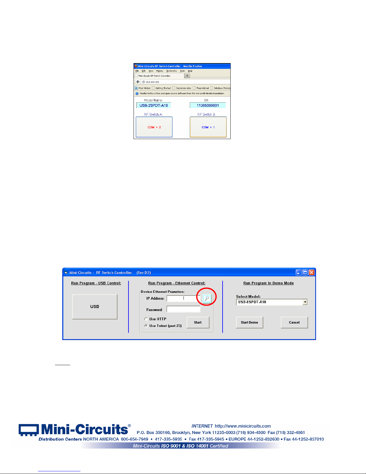
3.2.4 The Switch Controller Startup screen will appear. For USB control see
section 3.1, for Ethernet control either type the IP address or click on the search icon next to
the IP address field.
Figure 3.2.4: Switch Controller Startup screen
Depending on the browser used and your network configuration you may need to disable
Note:
the proxy server for your computer, or add the switch matrix's IP address to the list of addresses
in the proxy server.
AN-49-001 Rev.: A (November 25, 2014) M149081 (R88277) File: AN-49-002(A).doc
This document and its contents are the property of Mini-Circuits
Page 18 of 33
Page 19

3.2.5 After clicking on the search icon The IP search will pop up with a list of
switch matrix IP addresses found and their HTTP ports on the left side of the screen, and full
details of each unit on the right. Mark the IP address you wish to use and click select. The
search window will close and the IP address will be entered in the IP address field of the
initial screen automatically.
Figure 3.2.5: Ethernet IP search window
Notes:
Note:
1) To refresh the list of units found click on the Search button.
2) The search function uses ports UDP 4950 and UDP 4951 for communication, ensure
your firewall allows access to these ports.
3.2.6 After entering the IP address enter your password if you set one (see section
3.1.7), select the communication protocol you wish to use (HTTP or Telnet) and click start,
the unit's main screen will open.
changing Ethernet settings is only possible via USB control, see section 3.1.7 for details.
Figure 3.2.6: Ethernet startup screen
AN-49-001 Rev.: A (November 25, 2014) M149081 (R88277) File: AN-49-002(A).doc
This document and its contents are the property of Mini-Circuits
Page 19 of 33
Page 20

3.2.7 Telnet or HTTP text commands can also be used to control the Switch matrix.
Just type in the command in the address field of your internet browser or implement a
Get/Post HTTP function in your selected application (for HTTP) or establish a telnet
connection(for Telnet). A full list of the commands available and their syntax is available
in Mini-Circuits programming handbook chapter 2, and in a text file on the CD provided
with the switch matrix, in the Ethernet directory.
3.3 Switch Configurations
Several different preset configurations are available in the Mini-Circuits GUI switch controller
and are described below. Where external RF cables are required for the configuration this is
noted and the placement of the RF cables shown in the configuration screen. These preset
configurations are currently available only via USB control for complex configurations with timing
considerations or setting configurations via Ethernet control see Section 3.4.
3.3.1 USB-1SPDT-A18 / RC-1SPDT-A18
These models have only a single absorptive SPDT switch, and thus there are no additional
configurations beyond that of an SPDT switch. The switch state can be changed either by
clicking on the button above the switch drawing circled in Fig. 3.3.1 (the button will change
between ‘COM->2’ and ‘COM->1’ to indicate the current switch state) or in the user
sequence window, opened by clicking on the user sequence button (see section 3.4).
Figure 3.3.1: USB-1SPDT-A18 main window
AN-49-001 Rev.: A (November 25, 2014) M149081 (R88277) File: AN-49-002(A).doc
This document and its contents are the property of Mini-Circuits
Page 20 of 33
Page 21

3.3.2 USB-2SPDT-A18 / RC-2SPDT-A18
These models have two absorptive SPDT switches and can be configured as a DPDT or
SP3T switch in addition to two SPDT switches. In the default configuration each switch state
can be changed independently by either clicking on the button above the corresponding
switch drawing (the button will change between ‘COM->2’ and ‘COM->1’ to indicate the
current switch state) or in the user sequence window, opened by clicking on the user
sequence button (see section 3.4).
Figure 3.3.2: USB-2SPDT-A18 main window
3.3.2.1 USB-2SPDT-A18 / RC-2SPDT-A18 as a SP3T switch
Clicking on the ‘Use as SP3T switch’ button in the main window will transfer you to a new
window - the SP3T configuration screen. In order to use the switch box in this configuration
the user needs to connect external RF cable A as shown in Fig. 3.3.2.1. Clicking on the
switch state buttons on the right side of the screen will change the state of the switches
accordingly and the signal path and current state will be highlighted in green. In order to
return to the main window, click on the ‘Back to Main’ button.
A
Figure 3.3.2.1: USB-2SPDT-A18 SP3T configuration window
AN-49-001 Rev.: A (November 25, 2014) M149081 (R88277) File: AN-49-002(A).doc
This document and its contents are the property of Mini-Circuits
Page 21 of 33
Page 22

3.3.2.2 USB-2SPDT-A18 / RC-2SPDT-A18 as a DPDT switch
Clicking on the ‘Use as DPDT switch’ button in the initial screen will transfer you to a new
window - the DPDT configuration screen. This configuration does not require any external
RF cables to work. Clicking on the circled button will toggle both switches simultaneously as
a single DPDT switch. In order to return to the main window, click on the ‘Back to Main’
button.
Figure 3.3.2.2: USB-2SPDT-A18 DPDT configuration window
AN-49-001 Rev.: A (November 25, 2014) M149081 (R88277) File: AN-49-002(A).doc
This document and its contents are the property of Mini-Circuits
Page 22 of 33
Page 23

3.3.3 USB-3SPDT-A18 / RC-3SPDT-A18
These models have three absorptive SPDT switches and can be configured as a DPDT and
a SPDT or a 3PDT with no external RF cables needed (same procedure as section 3.3.2.2)
or as a SP3T and SPDT or SP4T switch with external RF cables as shown in the relevant
screen (same procedure as section 3.3.2.1) in addition to the base configuration as three
independent SPDT switches. In the default configuration each switch state can be changed
independently by either clicking on the button above the corresponding switch drawing (the
button will change between ‘COM->2’ and ‘COM->1’ to indicate the current switch state) or in
the user sequence window, opened by clicking on the user sequence button (see section
3.4).
Figure 3.3.3: USB-3SPDT-A18 main window
3.3.3.1 USB-3SPDT-A18 / RC-3SPDT-A18 as a SP3T, and an SPDT
switch
Connect RF cable A as shown in Fig. 3.3.3.1. Clicking on the buttons on the right will change
the state of the switches accordingly and the signal path and will be highlighted in green. In
order to return to the main window, click on the ‘Back to Main’ button.
Figure 3.3.3.1: USB-3SPDT-A18 as a SP3T and SPDT
A
AN-49-001 Rev.: A (November 25, 2014) M149081 (R88277) File: AN-49-002(A).doc
This document and its contents are the property of Mini-Circuits
Page 23 of 33
Page 24

3.3.3.2 USB-3SPDT-A18 / RC-3SPDT-A18 as a SP4T switch
Connect RF cables A and B as shown in Fig. 3.3.3.2. Clicking on the buttons on the right will
change the state of the switches accordingly and the signal path and will be highlighted in
green. In order to return to the main window, click on the ‘Back to Main’ button.
.
3.3.4 USB-4SPDT-A18 / RC-4SPDT-A18
These models have four absorptive SPDT switches and can be configured as two DPDT, a
3PDT and a SPDT, or a 4PDT with no external RF cables needed (same procedure as
section 3.3.2.2) or as two SP3T, a SP4T and a SPDT, a SP5T, or a transfer switch with
external RF cables as shown in he relevant screen (same procedure as section 3.3.2.1) in
addition to the default configuration of four independent SPDT switches. In the default
configuration each switch state can be changed independently by either clicking on the
button above the corresponding switch drawing (the button will change between ‘COM->2’
and ‘COM->1’ to indicate the current switch state) or in the user sequence window, opened
by clicking on the user sequence button (see section 3.4).
B
Figure 3.3.3.2: USB-3SPDT-A18 as SP4T
Figure 3.3.4: USB-4SPDT-A18 main window
A
AN-49-001 Rev.: A (November 25, 2014) M149081 (R88277) File: AN-49-002(A).doc
This document and its contents are the property of Mini-Circuits
Page 24 of 33
Page 25

3.3.4.1 USB-4SPDT-A18 / RC-4SPDT-A18 as a SP5T switch
Connect RF cables A, B and C as shown in Fig. 3.3.4.1. Clicking on the buttons on the right
will change the state of the switches accordingly and the signal path and will be highlighted
in green. In order to return to the main window, click on the ‘Back to Main’ button.
A
B
C
Figure 3.3.4.1: USB-4SPDT-A18 as SP5T
3.3.4.2 USB-4SPDT-A18 / RC-4SPDT-A18 as a SP4T, and a SPDT switch
Connect RF cables A and B as shown in Fig. 3.3.4.2. Clicking on the buttons on the right will
change the state of the switches accordingly and the signal path and will be highlighted in
green. In order to return to the main window, click on the ‘Back to Main’ button.
A
B
Figure 3.3.4.2: USB-4SPDT-A18 as a SP4T and SPDT
AN-49-001 Rev.: A (November 25, 2014) M149081 (R88277) File: AN-49-002(A).doc
This document and its contents are the property of Mini-Circuits
Page 25 of 33
Page 26

3.3.4.3 USB-4SPDT-A18 / RC-4SPDT-A18 as two SP3T switches
Connect RF cables A and B as shown in Fig. 3.3.4.3. Clicking on the buttons on the right will
change the state of the switches accordingly and the signal path and will be highlighted in
green. In order to return to the main window, click on the ‘Back to Main’ button.
A
Figure 3.3.4.3: USB-4SPDT-A18 as two SP3T
B
3.3.5 USB-8SPDT-A18 / RC-8SPDT-A18
This model has eight absorptive SPDT switches and can be configured in many different
configurations in similar fashion to those shown in previous sections in addition to the default
configuration of eight independent SPDT switches. In the default configuration each switch
state can be changed independently by either clicking on the button above the
corresponding switch drawing (the button will change between ‘COM->2’ and ‘COM->1’ to
indicate the current switch state) or in the user sequence window, opened by clicking on the
user sequence button (see section 3.4).
Figure 3.3.5: USB-8SPDT-A18 main window
AN-49-001 Rev.: A (November 25, 2014) M149081 (R88277) File: AN-49-002(A).doc
This document and its contents are the property of Mini-Circuits
Page 26 of 33
Page 27

3.3.6 USB-1SP4T-A18 / RC-1SP4T-A18
These models have only a single absorptive SP4T switch and thus there are no additional
configurations beyond that of an SP4T switch. The switch state can be changed either by
clicking on the buttons on the right side of the screen in Fig. 3.3.6 (the button will change
color to indicate the current switch state) or in the user sequence window, opened by clicking
on the ‘User Sequence’ button (see section 3.4).
Figure 3.3.6: USB-1SP4T-A18 main window
3.3.7 Additional configurations, not shown here
For additional configurations not mentioned here of all models, or for configurations via
Ethernet control click on the ‘User Sequence’ button to open the user sequence window.
AN-49-001 Rev.: A (November 25, 2014) M149081 (R88277) File: AN-49-002(A).doc
This document and its contents are the property of Mini-Circuits
Page 27 of 33
Page 28

3.4 User Sequence
Clicking on the ‘User Sequence’ button in the main window of any model will open a new
window – the User Switching sequence window (see Fig. 3.4.1). This screen allows the user to
run timed sequences of switching any of the switches in the model either individually or
together, and run external programs synchronized with the switching sequence.
3.4.1 User sequence screen buttons and indicators
# Name Description
Switching
1
Set Name
Switching
2
Sequence
Switch states
3
4
5
6
7
8
9
10
11
12
13
14
15
16
17
18
Insert Add the command above the current command
Add Add a command to end of sequence
Count Limit
Time Limit
Current Step Run current command and remain on the same step
Continuously
Stop Stop the continuous run loop of all commands in sequence
Back to Main Return to the initial screen of the model
View Switches
Remove Delete current command
Dwell ime
Exec Program
Clear List Delete all commands in sequence
Recall Recall a previously saved sequence
Save
Shows the name of the sequence displayed. If the sequence is not saved this
indicator will be blank.
The list of commands in the sequence with an arrow pointing to the current
command. Double clicking on the state of a switch in a command will change
its state.
Shows the state of each switch in the command. Double click on a state to
change it.
Enables setting a maximum number of cycles for the ‘run continuously’ option
– Need to enter a number or uncheck option before clicking on ‘run
continuously’
Enables setting a maximum duration for the ‘run continuously’ option – Need to
enter a value (in minutes) or uncheck option before clicking on ‘run
continuously’
Run all commands in the sequence, in a continuous loop until stopped by user
or reach specified limit (if limit is set)
When selected opens a graphical presentation window beside the user
sequence window (Fig 3.4.2)
The delay (in mSec) after toggling the switches to their new state before going
to the next step (in ‘run continuously’). If no value is entered the program will
proceed immediately to the next step
If you wish to run an external program after changing the switches to their
current state enter the file name here. File must be placed in
C:\MCL_SwitchBox
Save the sequence in one of 99 sequence registers. Unless specifically named
sequence will be saved as Seq-XX where XX is the register number.
AN-49-001 Rev.: A (November 25, 2014) M149081 (R88277) File: AN-49-002(A).doc
This document and its contents are the property of Mini-Circuits
Page 28 of 33
Page 29

1
2
3
4
5
6
7
8
18
17
16
15
14
13
12
11
9
10
Figure 3.4.1: User Switching Sequence screen
Notes:
1. Typical switching time is 25 mSec, attempting to toggle a given switch twice with too short a
delay between the commands may produce errors.
2. If time limit is set to a value which is not a multiple of sequence run time it will be rounded up
to nearest multiple.
3.4.2 User sequence graphical switch presentation
This window is opened beside the user sequence window by selecting the ‘View Switches’
option. This window shows the current state of all switches and allows you to illustrate multi
switch setups by ‘dragging’ one of the connector circles to another switch’s connector for
example 2(A) to COM(B) (see Fig. 3.4.2a).
Each connector can be connected to only one other connector and can not be connected to
another connector in the same switch. Adding a second line between switches to a
connector will erase the previous line and replace it with the new one.
Start and end of active signal paths are highlighted in the same color, with each signal path
using a different color while the inactive connectors will remain white.
Clicking on the tab of a connector allows you to type in a new name for the connector
instead of the default ‘1’, ‘COM’ or ‘2’.
AN-49-001 Rev.: A (November 25, 2014) M149081 (R88277) File: AN-49-002(A).doc
This document and its contents are the property of Mini-Circuits
Page 29 of 33
Page 30

Figure 3.4.2a
: User Switching graphical switch view window (8SPDT)
Figure 3.4.2
b: User Switching graphical switch view window (1SP4T)
Connections shown between switches need to be added by the user using external RF
Note:
cables.
AN-49-001 Rev.: A (November 25, 2014) M149081 (R88277) File: AN-49-002(A).doc
This document and its contents are the property of Mini-Circuits
Page 30 of 33
Page 31

CAUTION
3.5 Firmware update
3.5.1 Once the switch controller GUI is installed and started (see chapter 2) you
will note an (fw) indicator in the upper right corner of the main screen.
Figure 3.5.1 Firmware indicator on main screen
3.5.2 In order to update your switch matrix firmware, you must have a switch
matrix unit with firmware revision B3 or later and a Windows computer with Mini-Circuits’
Switch Controller software installed.
A power interrupt, to either the computer or the switch matrix while the firmware is being
updated may cause the firmware to be corrupted. It is therefore recommended to only
update the firmware while both the switch matrix and the computer are connected to an
Uninterruptable Power Supply (UPS).
3.5.3 Click on the ‘(fw)’ indicator, this will cause the firmware - info window to open
(See Fig. 3.3.3). The ‘Firmware’ listed is the version of the firmware installed in your switch
matrix. Click on “Update Firmware” to select a new firmware version to install or click ‘Exit’ to
close the firmware – info window.
Figure 3.5.4: Firmware Information Window
AN-49-001 Rev.: A (November 25, 2014) M149081 (R88277) File: AN-49-002(A).doc
This document and its contents are the property of Mini-Circuits
Page 31 of 33
Page 32

3.5.4 A browse window will open to the firmware directory under the path
you selected when installing the GUI program (See Fig. 3.3.4). Navigate to where you saved
your firmware file, Select the firmware version you wish to install and click ‘O.K’.
Figure 3.5.5: Firmware - Browse Window
3.5.5 The selected file will be installed in the switch matrix the process will take up to
a minute.
Figure 3.5.6: Firmware - Progress Bar Window
3.5.6 After the firmware has updated an alert will appear. Click ‘OK’ to shut down
the Switch Controller program and then restart it normally.
Figure 3.5.7: Firmware - Successful Update
AN-49-001 Rev.: A (November 25, 2014) M149081 (R88277) File: AN-49-002(A).doc
This document and its contents are the property of Mini-Circuits
Page 32 of 33
Page 33

3.6 Demo Mode
3.6.1 This mode allows you to see all the GUI functions of all switch matrix
models available in the catalog.
3.6.2 To start the Demo Mode select the model requested from the drop box in the
right side of the initial screen of the switch controller software. The default option of the demo
mode is USB-8SPDT-A18.
Figure 3.6.1: Demo mode selection screen
3.6.3 The main screen of the model selected will appear with all options
available for the model selected, however they are simulated, with no communication to any
unit connected to the computer. When in demo mode the unit S/N will show “not exist”
instead of the unit’s S/N and control method will be noted as "Demo control".
Figure 3.6.2: Demo mode 8SPDT main screen
AN-49-001 Rev.: A (November 25, 2014) M149081 (R88277) File: AN-49-002(A).doc
This document and its contents are the property of Mini-Circuits
Page 33 of 33
 Loading...