

Page 1
Mini-Circuits
Solid state
RoHS Compliant
See our web site for RoHS Compliance
methodologies and qualifications
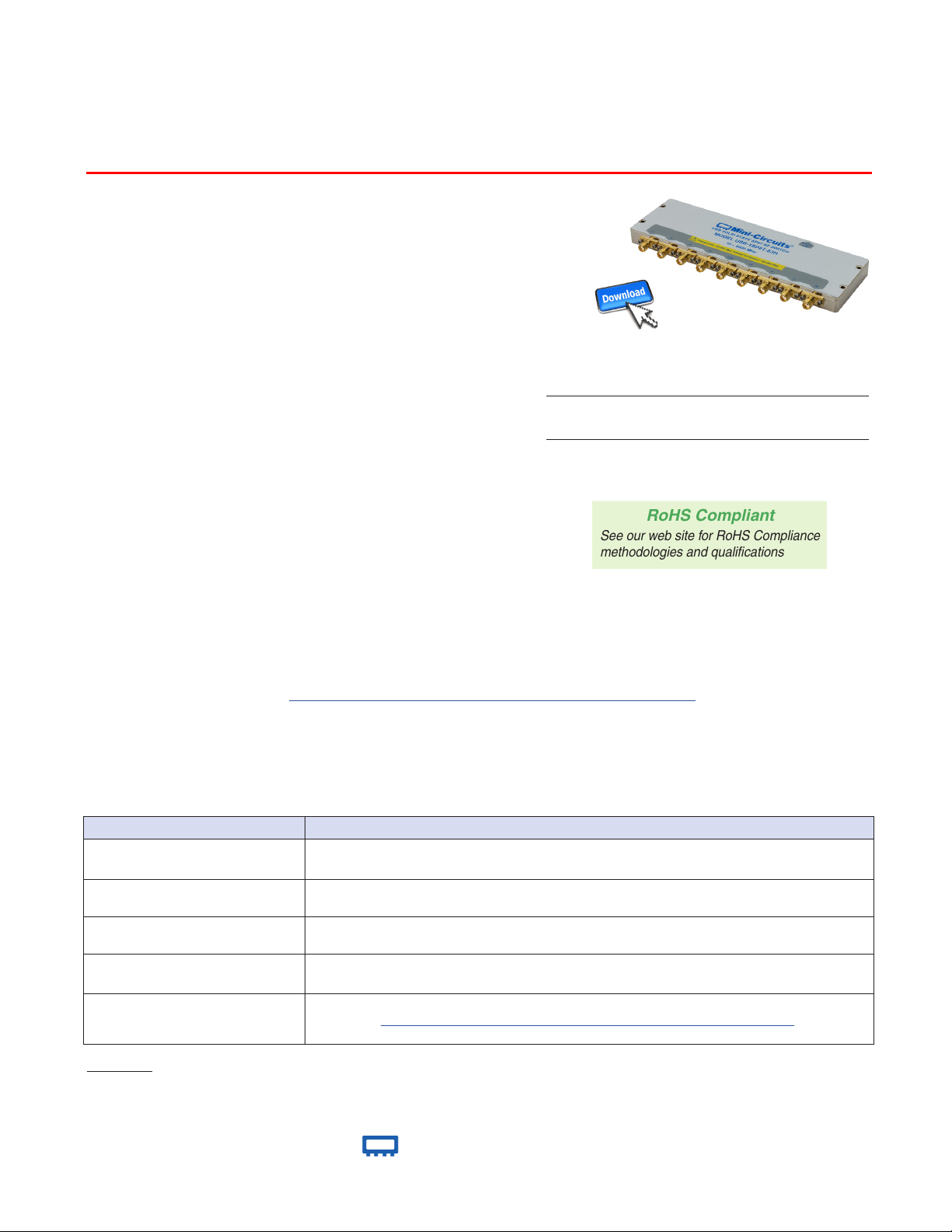
USB RF SP8T Switch
USB-1SP8T-63H
50Ω 10 to 6000 MHz
The Big Deal
• Very high isolation, 80 dB typ
• High speed switch transition, 200 ns typ
• High power handling, +30 dBm max
• Daisy-chain control of up to 35 modules
Typical Applications
• Cellular handset / BTS testing
• High volume production testing / ATE
• Design verication testing
• RF signal routing / switch matrices
Software Package
Model No. Description Qty.
USB-1SP8T-63H
Included Accessories
MUSB-CBL-3+ 2.6 ft USB cable 1
Case Style: QM2280
Switch Matrix 1
Product Overview
Mini-Circuits’ USB-1SP8T-63H is a low cost, absorptive SP8T switch with USB control. The fast switching, solid state switch operates
from 10 MHz to 6000 MHz with 200 ns typical switch transition speed. High linearity (+50 dBm typ IP3), and high isolation (80 dB
typical) allow the model to be used for a wide variety of RF applications.
Full software support is provided for USB control, including our user-friendly GUI application for Windows and a full API with
programming instructions for Windows and Linux environments (both 32-bit and 64-bit systems). The latest version of the full software
package can be downloaded from https://www.minicircuits.com/softwaredownload/solidstate.html at any time.
The USB-1SP8T-63H is housed in a compact, low prole, rugged metal case (6.5” x 2.00” x 0.475”) with 9 SMA (F) connectors (COM,
and J1 to J8), a USB Mini-B port for power and two data bus connectors for Master / Slave connections to other modules.
Key Features
Feature Advantages
RF SP8T absorptive switch
High Linearity (IP3 50 dBm typ.)
Internal DC Blocking capacitors
at RF ports
Dynamic daisy-chain control
Full software support included
Trademarks: Windows is a registered trademark of Microsoft Corporation in the United States and other countries. Linux is a registered trademark of Linus
Torvalds.
owners of the above referenced trademarks
Mini-Circuits and the Mini-Circuits logo are registered trademarks of Scientic Components Corporation.
Pentium is a registered trademark of Intel Corporation.
www.minicircuits.com P.O. Box 350166, Brooklyn, NY 11235-0003 (718) 934-4500 sales@minicircuits.com
Wideband (10 to 6000 MHz) with high isolation (80 dB typ.), and high power rating (+30
dBm through path) makes this switch suitable for a wide range of applications.
Results in little or negligible inter-modulation generation, meeting requirements for digital
communications signals
No need for external DC blocking circuitry
Simplify control software and interconnections by cascading up to 35 modules of multiple
switch types into a Master / Slave chain with a single USB interface.
Mini-Circuits’ full software package, programming and user manual are available for down
load from
cost.
https://www.minicircuits.com/softwaredownload/solidstate.html
Neither Mini-Circuits nor the Mini-Circuits USB-1SP8T-63H are afliated with or endorsed by the
®
at no extra
Rev. E
M177161
EDR-11446/1
USB-1SP8T-63H
RAV
201221
Page 1 of 9
Page 2
Mini-Circuits
USB RF SP8T Switch
USB-1SP8T-63H
Electrical Specications @ 0 to 50°C
Parameter Port Conditions Min. Typ. Max. Units
Operating Frequency 10 6000 MHz
10 to 700 MHz
Insertion Loss COM to any active port
Between any of ports J1 to J8
Isolation
COM to any terminated port
COM port
VSWR
Power Input
@1 dB Compression
2,3
IP3
Transition Time
Minimum dwell time
Switching Time (USB)
Supply voltage (Vcc)
Supply Current (Icc)
Current Pass-through
Operating RF Input
Power
1
Max power at through path derates linearly from +30 dBm @ 40 MHz to +23 dBm @10 MHz
2
Compression and IP3 may degrade below 100 MHz.
3
IP3 Tested with 1 MHz span between signals.
4
Transition time spec represents the time that the RF signal paths are interrupted during switching and thus is specified without communication delays.
5
Minimum dwell time is the shortest time that can be achieved between 2 switch transitions when programming an automated switch sequence.
6
Switching time(USB) is the time from issuing a single software command via USB to the switch state changing. The most significant factor is the host PC, influenced
by CPU load and USB protocol. The time shown is an estimate for a medium CPU load and USB 2.0 connection.
7
Current consumption specied for a single unit without any slave modules.
8
Pass through current is the maximum current handling of a unit with slave modules attached. If controlling a large number of slave modules additional power supplies
should be included to ensure this limit is not exceeded. See page 5 for details.
4
1
Any port connected to COM
Any terminated port
COM to any active port 100 to 6000 MHz − 35 − dBm
1,2
COM to any active port 100 to 6000 MHz − 50 − dBm
5
6
7
8
Any active port to COM port Hot Switching − − +23
Any active port to COM port Cold Switching − − +30
− − − 200 300 ns
High Speed Mode − − 25 − µs
− − − 2 − ms
USB port
Any terminated port − − − +23
COM to any port
700 to 2500 MHz − 3.9 5.5
2500 to 5000 MHz − 5.2 6.5
5000 to 6000 MHz
10 to 700 MHz
700 to 2500 MHz 70 87 −
2500 to 5000 MHz 52 69 −
5000 to 6000 MHz
10 to 700 MHz
700 to 5000 MHz 73 98 −
700 to 5000 MHz 58 76 −
5000 to 6000 MHz
10 to 700 MHz
700 to 2500 MHz − 1.25 −
2500 to 5000 MHz − 1.25 −
5000 to 6000 MHz
10 to 700 MHz
700 to 2500 MHz − 1.25 −
2500 to 5000 MHz − 1.25 −
5000 to 6000 MHz
10 to 700 MHz
700 to 2500 MHz − 1.15 −
2500 to 5000 MHz − 1.15 −
5000 to 6000 MHz
− 4.75 5 5.25 V
− − 55 85
− − − 500
− − − +30
− 3.2 4.5
− 5.8 7.5
80 100 −
50 60 −
78 100 −
54 65 −
− 1.40 −
− 1.25 −
− 1.45 −
− 1.25 −
− 1.15 −
− 1.20 −
dB
dB
:1
DC
mA
dBm
®
www.minicircuits.com P.O. Box 350166, Brooklyn, NY 11235-0003 (718) 934-4500 sales@minicircuits.com
Page 2 of 9
Page 3
Mini-Circuits
USB RF SP8T Switch
Control & Power
Control & Power
USB-1SP8T-63H
Absolute Maximum Ratings
Operating Temperature 0°C to 50°C
Storage Temperature -20°C to 60°C
DC supply voltage max. 6V
RF power @ 10 - 6000 MHz into termination +24 dBm
RF power @ Through
path
DC voltage @ RF Ports 16V
Permanent damage may occur if any of these limits are exceeded. Operating in the range
between operating power limits and absolute maximum ratings for extended periods of time may
result in reduced life and reliability.
10 to 40 MHz
40 to 6000 MHz +35 dBm
Derate linearly from +35 dBm @ 40
MHz to +30 dBm @10 MHz
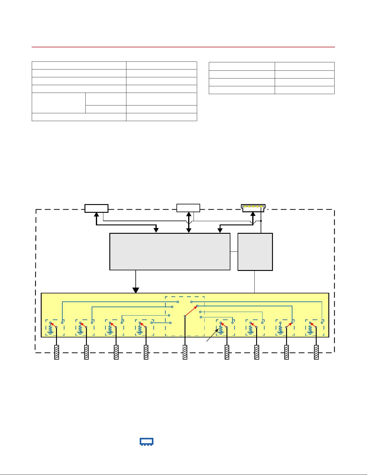
Simplied Diagram
to slaves (Serial Out)
Supply Out
from Master (Serial In)
Supply In
Connections
RF SP8T Switch (J1 to J8, COM) (SMA female)
USB (USB type Mini-B receptacle)
Serial In (Digital Control 2 port) (Digital Snap Fit Connector)
Serial Out (Digital Control 1 port) (Digital Snap Fit Connector)
USB
J1
50Ω
J2
50Ω
J3
50Ω
MICROCONTROLLER
Control
ABSORPTIVE SP8T SWITCH
Control
J4
50Ω
Switch in COM to 7 state
1
2
3
4
COM
50Ω
8
7
6
5
Internal
Termination
J5
50Ω
Voltage
regulator
J6
50Ω
J7
50Ω
J8
50Ω
®
www.minicircuits.com P.O. Box 350166, Brooklyn, NY 11235-0003 (718) 934-4500 sales@minicircuits.com
Page 3 of 9
Page 4

Mini-Circuits
USB RF SP8T Switch
USB-1SP8T-63H
Connecting multiple modules (Daisy Chain)
The USB-1SP8T-63H is designed to connect up to 35 modules in series (Daisy chain) using dynamic addressing, meaning there is no
need to specically set the address of the modules, the addresses will be set automatically as part of establishing the communications
with the PC. The module connected to the PC USB port will be assigned address 0 (Master), the rst module connected to it will get
address 1(slave) and subsequent modules incrementing up to address 34 (slave).
USB control
(limited to 500mA max)
USB Serial Ctrl In Serial Ctrl Out
Module 0
RF Connectors
Master
USB Serial Ctrl In Serial Ctrl Out
Module 1
RF Connectors
Slave 1
power adaptor
USB Serial Ctrl In Serial Ctrl Out
Module 2
RF Connectors
Slave 2
Additional power supply will need to
be connected every sixth Module.
USB Serial Ctrl In Serial Ctrl Out
Module 34
RF Connectors
Slave 34
Connections between modules will be made using the serial in/out ports with the module connected to the PC as a master and all
others as slave modules. All control will be through the master module (address zero) which is the only one communicating with the
PC. Serial control out port of each module should be connected to the serial control in port of the next module. Power will be supplied
from the PC via the master module up to a maximum of 500mA.
If connecting USB-1SP8T-63H units in series, additional power supply will generally be needed every six to nine modules. If mixing
modules of different types ensure the max current through any unit does not exceed 500mA. All power supplies should be connected
to the module via the module’s USB port, connecting an additional power supply will automatically cut off power draw from the serial
control in port for that module.
The Serial master/slave bus allows connecting modules of different types to the same daisy chain as long as all support Mini-Circuits
Dynamic addressing setup. To add a new module to the set up simply connect the module to the setup and refresh the address listing,
no need to reset any of the existing modules or assign addresses manually.
Connecting slave units should be done only with control cables provided by Mini-Circuits
®
www.minicircuits.com P.O. Box 350166, Brooklyn, NY 11235-0003 (718) 934-4500 sales@minicircuits.com
Page 4 of 9
Page 5

Mini-Circuits
USB RF SP8T Switch
Outline Drawing (QM2280)
USB-1SP8T-63H
Outline Dimensions ( )
A B C D E F G H J K L
6.50 2.00 0.475 0.217 0.69 0.640 6.300 1.000 0.10 0.50 0.106
165.1 50.8 12.07 5.51 17.53 16.26 160.02 25.40 2.54 12.70 2.69
inch
mm
WT. GRAMS
400
CHECK PRINT (FOR INTERNAL USE ONLY)
File Rev Source Date
98-QM2470 D
B16-10-251+ A
e-mail from
Haim H.
jpg from
source les
Nov 20,
2019
Dec 17,
2020
®
www.minicircuits.com P.O. Box 350166, Brooklyn, NY 11235-0003 (718) 934-4500 sales@minicircuits.com
Page 5 of 9
Page 6

Mini-Circuits
USB RF SP8T Switch
2.0
3.0
4.0
5.0
6.0
7.0
0 1000 2000 3000 4000 5000 6000
Insertion Loss (dB)
Insertion Loss over Temp.
@ 0°C
@ +25°C
@ +50°C
2.0
3.0
4.0
5.0
6.0
7.0
0 1000 2000 3000 4000 5000 6000
Insertion Loss (dB)
Insertion Loss of all outputs in switch
vs. Frequency
COM - J1
COM - J2
COM - J3
COM - J4
COM - J5
COM - J6
COM - J7
COM - J8
1.0
1.2
1.4
1.6
1.8
2.0
0 1000 2000 3000 4000 5000 6000
VSWR (:1)
VSWR Active Port over Temp.
@ 0°C
@ +25°C
@ +50°C
1.0
1.2
1.4
1.6
1.8
2.0
0 1000 2000 3000 4000 5000 6000
VSWR (:1)
VSWR Common Port over Temp.
@ 0°C
@ +25°C
@ +50°C
1.0
1.2
1.4
1.6
1.8
2.0
0 1000 2000 3000 4000 5000 6000
VSWR (:1)
VSWR Internal Term. over Temp.
@ 0°C
@ +25°C
@ +50°C
1.0
1.2
1.4
1.6
1.8
2.0
0 1000 2000 3000 4000 5000 6000
VSWR(:1)
VSWR of all active ports in switch
vs. Frequency
Port 1
Port 2
Port 3
Port 4
Port 5
Port 6
Port 7
Port 8
Typical Performance Curves
Frequency (MHz) Frequency (MHz)
USB-1SP8T-63H
Frequency (MHz)
Frequency (MHz)
www.minicircuits.com P.O. Box 350166, Brooklyn, NY 11235-0003 (718) 934-4500 sales@minicircuits.com
Frequency (MHz)
Frequency (MHz)
®
Page 6 of 9
Page 7

Mini-Circuits
USB RF SP8T Switch
40
60
80
100
120
140
0 1000 2000 3000 4000 5000 6000
Isolation (dB)
Isolation J1 to J2 with J1 active
@ 0°C
@ +25°C
@ +50°C
40
60
80
100
120
140
0 1000 2000 3000 4000 5000 6000
Isolation (dB)
Isolation COM to J2 with J1 active
@ 0°C
@ +25°C
@ +50°C
40
60
80
100
120
140
0 1000 2000 3000 4000 5000 6000
Isolation (dB)
Isolation COM to J7 with J5 active.
@ 0°C
@ +25°C
@ +50°C
40
60
80
100
120
140
0 1000 2000 3000 4000 5000 6000
Isolation (dB)
Isolation J4 to J5 with J4 active
@ 0°C
@ +25°C
@ +50°C
40
60
80
100
120
140
0 1000 2000 3000 4000 5000 6000
Isolation (dB)
Isolation COM to J7 with J8 active.
@ 0°C
@ +25°C
@ +50°C
40
60
80
100
120
140
0 1000 2000 3000 4000 5000 6000
Isolation (dB)
Isolation J7 to J8 with J8 active
@ 0°C
@ +25°C
@ +50°C
Typical Performance Curves (Continued)
Frequency (MHz) Frequency (MHz)
USB-1SP8T-63H
Frequency (MHz) Frequency (MHz)
Frequency (MHz) Frequency (MHz)
www.minicircuits.com P.O. Box 350166, Brooklyn, NY 11235-0003 (718) 934-4500 sales@minicircuits.com
®
Page 7 of 9
Page 8

Mini-Circuits
USB RF SP8T Switch
USB-1SP8T-63H
Software & Documentation Download:
• Mini-Circuits’ full software and support package including user guide, Windows GUI, DLL les, programming manual and
examples can be downloaded free of charge from
https://www.minicircuits.com/softwaredownload/solidstate.html
• Please contact testsolutions@minicircuits.com for support
Minimum System Requirements
Parameter Requirements
Interface USB HID
GUI Windows 32 & 64 bit systems from Windows 98 up to Windows 10
System requirements
Hardware Pentium ® II or higher, RAM 256 MB
USB API (ActiveX & .Net) Windows 32 & 64 bit systems with ActiveX or .Net support from Windows 98 up to Windows 10
Daisy Chain Dynamic addressing Additional unit of this model or another Mini-Circuits model supporting Dynamic addressing
USB direct programming support Linux, Windows systems from Windows 98 up to Windows 10
Graphical User Interface (GUI) for Windows
Key Features:
• Set each switch manually
• Set timed sequence of switching states
• Congure switch address and upgrade Firmware
• Controlling up to 35 modules in ‘daisy chain’ conguration
Application Programming Interface (API)
Windows Support:
• API DLL les exposing the full switch functionality See programming manual at https://www.minicircuits.com/
softwaredownload/Prog_Manual-Solid_State_Switch.pdf for details
• ActiveX COM DLL le for creation of 32-bit programs
• .Net library DLL le for creation of 32 / 64-bit programs
• Supported by most common programming environments (refer to application note AN-49-001 for summary of tested
environments)
Linux Support:
• Full switch control in a Linux environment is achieved by way of USB interrupt commands. See programming manual at
https://www.minicircuits.com/softwaredownload/Prog_Manual-H_Series_Switches.pdf for details
®
www.minicircuits.com P.O. Box 350166, Brooklyn, NY 11235-0003 (718) 934-4500 sales@minicircuits.com
Page 8 of 9
Page 9

Mini-Circuits
USB RF SP8T Switch
Ordering, Pricing & Availability Information see our web site
Model Description
USB-1SP8T-63H
Included Accessories Part No. Description
USB
RF SP8T Switch
USB-1SP8T-63H
MUSB-CBL-3+
2.6 ft (0.8 m) USB Cable: USB type A(Male) to USB
type Mini-B(Male)
Optional Accessories Description
MUSB-CBL-3+ (Spare)
MUSB-CBL-7+ 6.6 ft (2.0 m) USB Cable: USB type A(Male) to USB type Mini-B(Male)
CBL-1.5FT-MMD+ 1.5 ft cable assembly for serial control Daisy Chain with snap t connectors
USB-AC/DC-5+ AC/DC +5V power adaptor with USB connector
9
The USB-AC/DC-5 may be used to provide additional power if needing to connect a number of switches in series exceeding 500mA total current draw.
10
Includes power plugs for US, UK, EU, IL, AU & China. Plugs for other countries are also available, if you need a power plug for a country not listed please
contact testsolutions@minicircuits.com
2.6 ft (0.8 m) USB Cable: USB type A(Male) to USB type Mini-B(Male)
9,10
CHECK PRINT (FOR INTERNAL USE ONLY)
MODEL: USB-1SP8T-63H (Rev. E) Updated by Z.M.
NAME (PRINT) SIGNATURE Date FILE SIZE
Michael M. ___Dec 2020
Ilan R. ___Dec 2020
Efron F. ___Dec 2020
David E. ___Dec 2020
Additional Notes
A. Performance and quality attributes and conditions not expressly stated in this specication document are intended to be excluded and do not form a part of this
specication document.
B. Electrical specications and performance data contained in this specication document are based on Mini-Circuit’s applicable established test performance criteria and
measurement instructions.
C. The parts covered by this specication document are subject to Mini-Circuits standard limited warranty and terms and conditions (collectively, “Standard Terms”);
Purchasers of this part are entitled to the rights and benets contained therein. For a full statement of the Standard Terms and the exclusive rights and remedies
thereunder, please visit Mini-Circuits’ website at www.minicircuits.com/MCLStore/terms.jsp
®
www.minicircuits.com P.O. Box 350166, Brooklyn, NY 11235-0003 (718) 934-4500 sales@minicircuits.com
Page 9 of 9
 Loading...