

Mini-Circuits U2C-1SP2T-63VH, USB-2SP2T-DCH, USB-4SP2T-63H, USB-1SP8T-63H, USB-1SP16T-83H User Manual
...Page 1
AN-49-012 Rev.:B (January 10, 2019) M171660 (R94356) File: AN-49-012(B).doc
This document and its contents are the property of Mini-Circuits
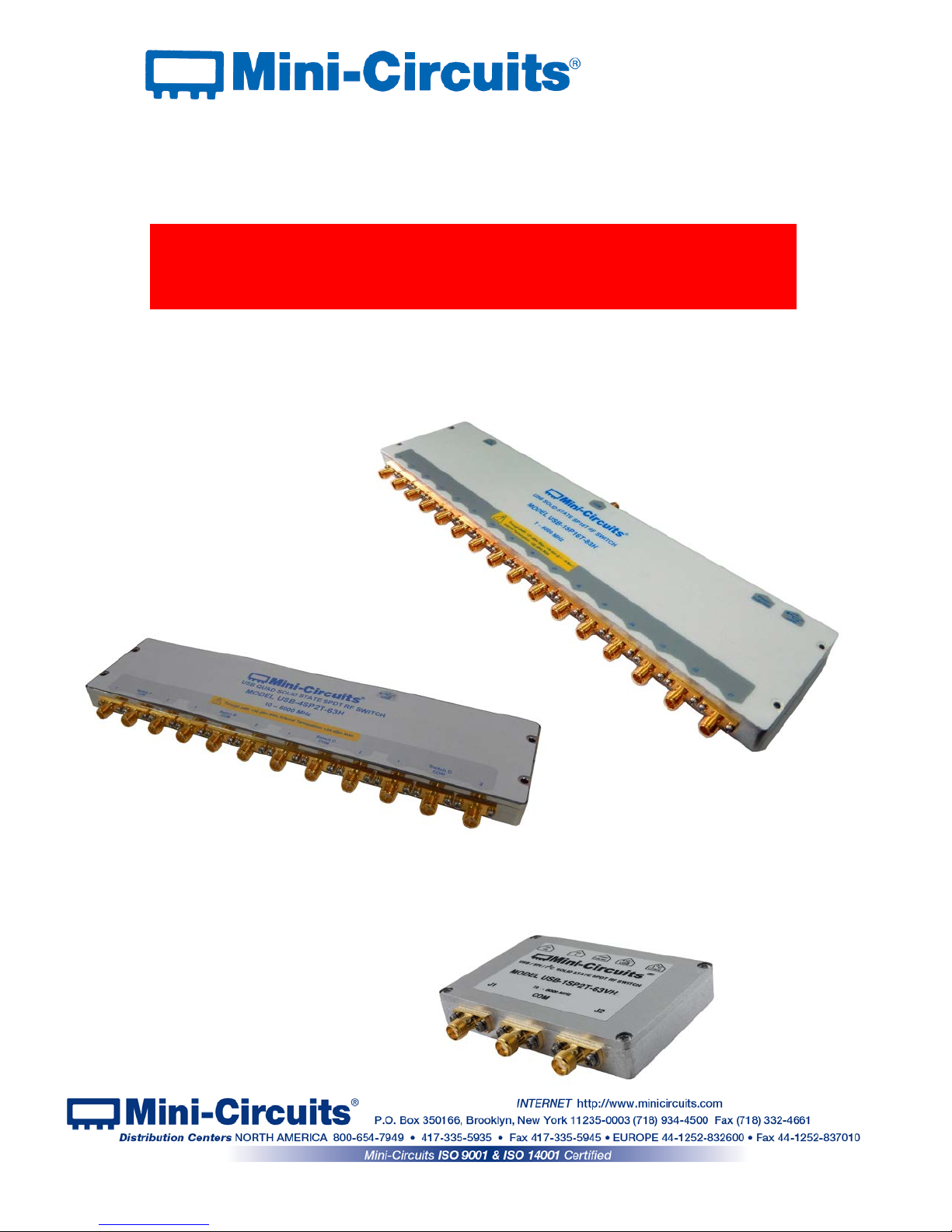
User Guide
USB/I2C/SPI/TTL High Isolation Solid State
RF Switch Modules
Page 2

Important Notice
This guide is owned by Mini-Circuits and is protected by copyright, trademark
and other intellectual property laws.
The information in this guide is provided by Mini-Circuits as an accommodation
to our customers and may be used only to promote and accompany the
purchase of Mini-Circuits’ Parts. This guide may not be reproduced, m odif ied,
distributed, published, stored in an electronic database, or transmitted and the
information contained herein may not be exploited in any form or by any means,
electronic, mechanical recording or otherwise, without prior written perm ission
from Mini-Circuits.
This guide is subject to change, qualifications, variations, adjustments or
modifications without notice and may contain errors, omissions, inaccuracies,
mistakes or deficiencies. Mini-Circuits assumes no responsibility for, and will
have no liability on account of, any of the foregoing. Accordingly, this guide
should be used as a guideline only.
Trademarks
Microsoft, Windows, Visual Basic, Visual C# and Visual C++ are registered
trademarks of Microsoft Corporation. LabVIEW and CVI are registered
trademarks of National Instruments Corporation. Delphi is a registered
trademark of Delphi Technologies, Inc. MATLAB is a registered trademark of
The MathWorks, Inc. Agilent VEE is a registered trademark of Agilent
Technologies, Inc. Linux is a registered trademark of Linus Torvalds. Mac is a
registered trademark of Apple Inc. Python is a registered trademark of Python
Software Foundation Corporation.
All other trademarks cited within this guide are the property of their respective
owners. Neither Mini-Circuits nor the Mini-Circuits solid state RF switches are
affiliated with or endorsed or sponsored by the owners of the above referenced
trademarks.
Mini-Circuits and the Mini-Circuits logo are registered trademarks of Scientific
Components Corporation.
Mini-Circuits
13 Neptune Avenue
Brooklyn, NY 11235, USA
Phone: +1-718-934-4500
Email: sales@minicircuits.com
Web: www.minicircuits.com
Page 2 of 23
AN-49-012 Rev.: (January 10, 2019) M171660 (R94356) File: AN-49-012(B).doc
This document and its contents are the property of Mini-Circuits
Page 3

Table of Contents
Chapter 1 – General Information ......................................................... 5-8
1.1 Scope of the User Guide ..................................................................................... 5
1.2 Warranty ............................................................................................................. 5
1.3 Definitions ........................................................................................................... 5
1.4 General safety precautions ................................................................................. 5
1.5 Introduction ......................................................................................................... 5
1.6 Service and Calibration ....................................................................................... 6
1.7 Contact Information ............................................................................................. 6
1.8 Technical description ....................................................................................... 6-8
1.8.1 Features of Mini-Circuits ........................................................................................... 6
1.8.2 Model Selection Guide ............................................................................................... 7
1.8.3 Intended Applications ................................................................................................. 7
1.8.4 Conformity .................................................................................................................. 7
1.8.5 Supported Software environments ............................................................................. 7
1.8.6 Included Accessories and Options ............................................................................. 8
Chapter 2 – Installation and Setup .................................................... 9-12
2.1 Software Setup ................................................................................................... 9
2.2 Installation .................................................................................................... 10-11
2.3 Switch control and power Setup .................................................................. 12-14
2.3.1 USB Control ............................................................................................................. 12
2.3.2 I2C Control (for U2C models) ................................................................................... 12
2.3.3 SPI Control (U2C-1SP2T-63VH only) ...................................................................... 13
2.3.4 TTL Control (USB-1SP16T-83H only) ...................................................................... 14
Page 3 of 23
AN-49-012 Rev.: (January 10, 2019) M171660 (R94356) File: AN-49-012(B).doc
This document and its contents are the property of Mini-Circuits
Page 4

Table of Contents
Chapter 3 – Using Mini-Circuits' GUI ............................................. 15-22
3.1 USB interface ............................................................................................... 15-16
3.2 Sequence Mode ........................................................................................... 17-19
3.3 Firmware update & recovery ....................................................................... 20- 22
Chapter 4 – Revision history ................................................................ 23
Page 4 of 23
AN-49-012 Rev.: (January 10, 2019) M171660 (R94356) File: AN-49-012(B).doc
This document and its contents are the property of Mini-Circuits
Page 5
1 Chapter 1 – General Information
1.1 Scope of the User Guide
This user guide provides general introduction, installation instruct i ons and operating information
for Mini-Circuits USB high isolation (H-series) solid state switch modules. For information on
Mini-Circuits USB/Ethernet mechanical switches please see:
https://www.minicircuits.com/app/AN49-002.pdf
For information on USB-SP4T-63 solid state switch see:
https://www.minicircuits.com/app/AN49-009.pdf
1.2 Warranty
See Mini-Circuits website http://www.minicircuits.com/support/ordering.html for warranty
information.
1.3 Definitions
Note: A note advises on important information you may need to ensure proper operation of the equipment.
There is no risk to either the equipment or the user.
A caution advises about a condition or procedure which can cause damage to the
equipment (no danger to users).
A warning alerts to a possible risk to the user and steps to avoid it. DO NOT proceed
until you are sure you understand the warning.
1.4 General safety precautions
Please observe the following safety precautions at al l times when using Mini-Circuits USB
RF switch modules.
Ensure that all instruments using mains power supply are properly grounded to
prevent risk of electrical shock.
1. Do not attempt to switch signals of greater power than the switch is rated for in its
datasheet.
2. Safe power input degrades below specified frequency range. Do not input signals
below the specified frequency range.
1.5 Introduction
Mini-Circuits has developed a new series of solid state USB RF switch modules in rugged, low
profile cases. Switches covering DC to 8GHz with up to 4 switches in a unit of various types
from SPDT to SP16T are available. Despite being solid state switches with the high speed and
reliability expected from such switches Mini-Circuits’ USB solid state switch modules also
provide very high isolation (80 - 110 dB depending on model) and can handle up t o 4 W power
terminated internally.
The switches can be controlled via the supplied GUI, or most common lab test soft ware using
supplied DLLs. Mini-Circuits even provides the command codes for direct control (See
programming guide for details) and also have addit i onal control methods from direct parallel
control at TTL voltage to SPI allowing many unit s t o be connected in a daisy chain.
CAUTION
WARNING
WARNING
CAUTION
Page 5 of 23
AN-49-012 Rev.: (January 10, 2019) M171660 (R94356) File: AN-49-012(B).doc
This document and its contents are the property of Mini-Circuits
Page 6

1.6 Service and Calibration
The solid state switch modules do not require any periodic service or calibration. The only user
service possible for the switch is external cleani ng of the case and connectors as needed. Do
not use any detergents or spray cleaning solution s t o clean the switch. To clean the connectors
use an alcohol solution, and to clean the case a soft, damp cloth.
1.7 Contact Information
Mini-Circuits inc.
13 Neptune Ave
Brooklyn, NY 11235
Phone: 1-718-934-4500
General Fax: 1-718-332-4661
Sales / Customer Service Fax: 1-718-934-7092
sales@minicircuits.com
For regional offices and tech support see
http://www.minicircuits.com/contact/offices.html
1.8 Technical description
1.8.1 Features of Mini-Circuits Switch modules
• Absorptive solid state switch
• Wide band frequency range (model dependant).
• High speed switching
• Electronic switching; high isolation; high reliability, life not related t o s w itching cycles.
• High power handling (model depend ent)
• All RF ports SMA(F)
• Programmable, timed switching sequence
• Easy GUI installation and operation, simplif ies complex switching and timing setups
• USB HID ”plug & play” device
• ActiveX com object and .Net class library for use with other software: C++, C#, CVI
®
, Delphi®, LabVIEW®
8 or newer, MATLAB® 7 or newer, Python, Agilent VEE®, Visual Basic®, Visual Studio® 6 or newer, and
more(see programming manual and application note
AN-49-001 for details)
• User friendly Graphical User Interface for any Windows® 32 or 64 bit computer command line support
for Linux
®
computers
• All power via USB
For Additional details, performance data and gra phs, outline drawing, ordering information and
environmental specifications, see our catalog at:
https://www.minicircuits.com/WebStore/PortableTestEquipment.html
Page 6 of 23
AN-49-012 Rev.: (January 10, 2019) M171660 (R94356) File: AN-49-012(B).doc
This document and its contents are the property of Mini-Circuits
Page 7
1.8.2 Model Selection Guide
Model Name
Frequency
Range
(MHz)
Switch
Type
Number of
switches in
module
Max Input
Power
(W)
Control Protocols
U2C-1SP2T-63VH
10 - 6000 SPDT 1 2 USB, SPI & I2C
USB-2SP2T-DCH
DC* - 8000
SPDT 2 3.15 USB
USB-4SP2T-63H
1 - 6000 SPDT 4 1 USB
U2C-1SP4T-63H
1 - 6000 SP4T 1 1 USB & I2C
USB-2SP4T-63H
1 - 6000 SP4T 2 1 USB
USB-1SP8T-63H
1 - 6000 SP8T 1 1 USB
USB-1SP16T-83H
1 - 8000 SP16T 1 1 USB & TTL(parallel)
* True DC, passes DC current up to 60mA.
1.8.3 Intended Applications
Mini-Circuits solid state high isolation switches are intended for i ndoor use in:
- Lab and test equipment setups for both manual and automated measurements
- Control systems
- Automated switching of signal paths in a complex system
The models can be used by anyone familiar with the basics of electronics measurements or
electronic control systems.
1.8.4 Conformity
Mini-Circuits USB solid state switches conform to all requirements for the following
international standards
:
RoHS – The model complies with EU directive for Restriction of Hazardous Substances
for 6 substances.
USB 2.0 – The model meets the specifications of the Universal Serial Bus Ver. 2.0
communication standard as described by USB-IF.
USB HID – The model meets the requirements for Universal S erial Bus Human
Interface Devices according to USB-IF’s Device Class Definition for Human
Interface Devices firmware rev. 1.11.
I
2
C – Models with U2C prefix also meet requirements for an I2C slave device as defined
in Rev 6 of the I
2
C bus specification and user manual.
1.8.5 Supported Software environments
Mini-Circuits USB solid state switches have been tested in the following operating systems:
32 bit systems: Windows 10, Windows 8, Windows 7, Windows Vista, Windows XP Windows
98
64 bit systems: Windows 10, Windows 8, Windo ws 7, Windows Vista, Linux
The switches will work with almost any software environment that supports ActiveX or .Net
including:
C++, C#, CVI®, Delphi®, LabVIEW® 8 or newer, MATLAB® 7 or newer, Python, Agilent VEE®,
Visual Basic®, AutoIT, Visual Studio® 6 or newer, and more
For more information see the Solid State Switch modules Programming Manual and
application note
AN-49-001 on our website.
Page 7 of 23
AN-49-012 Rev.: (January 10, 2019) M171660 (R94356) File: AN-49-012(B).doc
This document and its contents are the property of Mini-Circuits
Page 8

1.8.6 Included Accessories and Options
The solid state switches are suppli ed with a 2.6 ft' USB cable, additio nally the following accessory
options are available:
• Software (Windows GUI program, .net and A c tiveX DLL, and codes for direct contr ol in Linux
environment) can be downloaded from:
https://www.minicircuits.com/softwaredownload/solidstate.html
• 6.6 ft (2m) USB cable
• Control cables for secondary control m ethods (see model datasheet for details)
• For additional details and orderin g i nformation, see:
https://www.minicircuits.com/WebStore/PortableTestEquipment.html
Page 8 of 23
AN-49-012 Rev.: (January 10, 2019) M171660 (R94356) File: AN-49-012(B).doc
This document and its contents are the property of Mini-Circuits
Page 9
2 Chapter 2 – Installation and Setup
System requirements for the switch are a computer (Pentium II or better) with support for USB
HID. To run the GUI program a Windows operating system for either 32 or 64 bits is also
required. For secondary control methods (I
2
C, SPI, etc ) a master unit supporting those control
methods may be needed.
2.1 Software Setup
If you have had any problems installing the software, we’re here to help.
Try following these complete step-by-step instructions. I f you stil l experience problems,
give us a call at Mini-Circuits Worldwide Technical su pport . It’s (718) 934-4500 or e-mail
apps@minicircuits.com for North Americ a, or go to minicircuits.com/contact/worldwide_
tech_support.html for other regional numbers and addresses.
2.1.1 First save all work in progress and close any other programs that may be running.
2.1.2 Next, Insert the Mini-Circuits CD into the CD-ROM drive, or download the full CD
software from minicircuits.com. If instal li ng from files downloaded from the web - unzip the
downloaded files to a temporary folder on your de sktop or C: drive, then open the file folder
you created and double-click the “Install” icon.
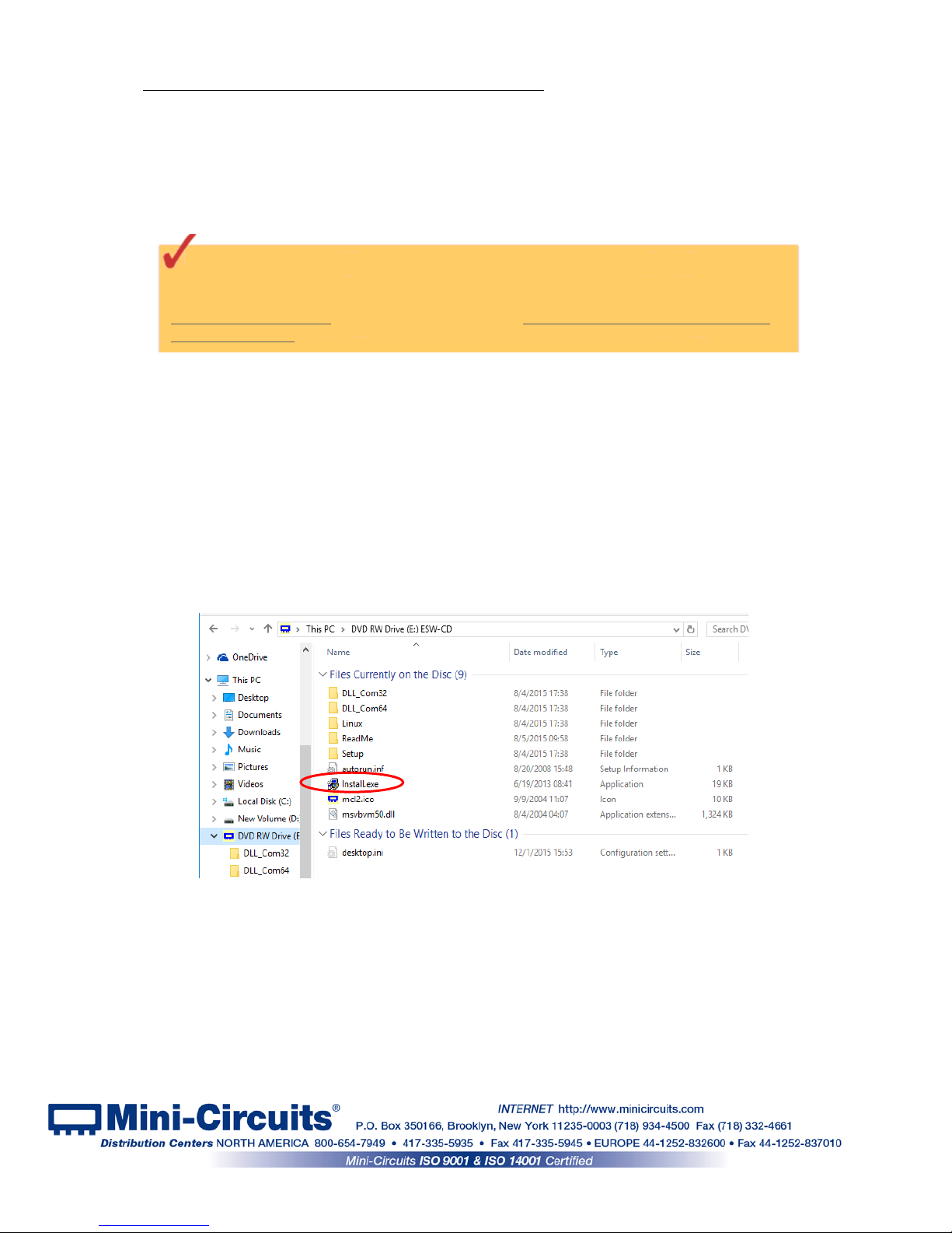
2.1.3 If installation from the CD does not start automatically, run
install.exe from the <CD drive> root directory.
Figure 2.1.3 CD file listing window
Page 9 of 23
AN-49-012 Rev.: (January 10, 2019) M171660 (R94356) File: AN-49-012(B).doc
This document and its contents are the property of Mini-Circuits
Page 10

Figure 2.2.1 Installation window
2.2 Installation
2.2.1 The installer window should now appear. Click the “Install Now” button.
2.2.2 The license agreement should now appear. To proceed, click “I Agree” and
the “Continue” button.
Figure 2.2.2 License agreement
2.2.3 The installation program will launch. Click the “OK” button to continue.
Figure 2.2.3 Installation Program window
Page 10 of 23
AN-49-012 Rev.: (January 10, 2019) M171660 (R94356) File: AN-49-012(B).doc
This document and its contents are the property of Mini-Circuits
Page 11
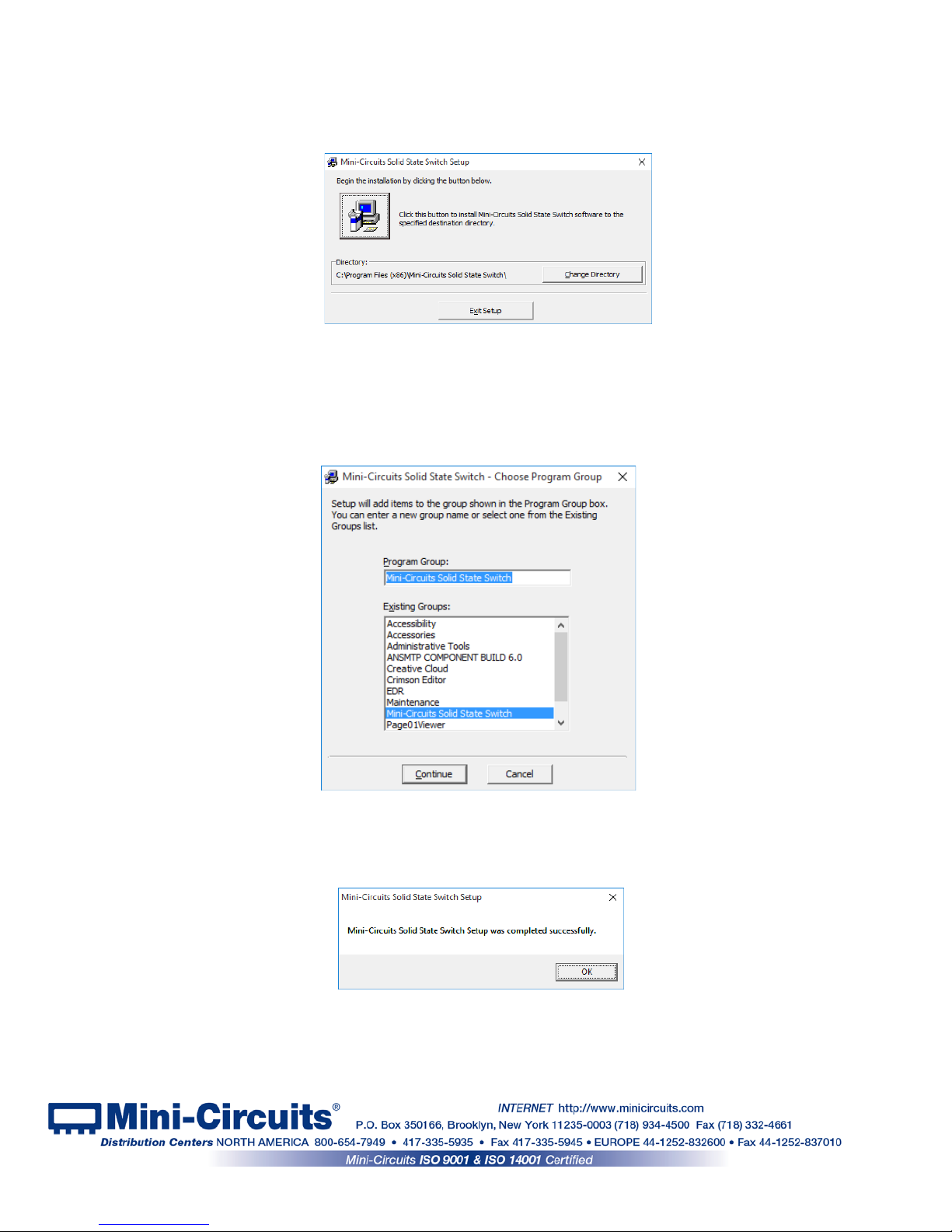
Figure 2.2.6: Installation complete
2.2.4 The destination directory window will appear. At this point it’s a good idea to
take a second and confirm the full destination address for the software. In most cases, the
default will be your computer’s hard drive (C:)\Program Files (x86)\Mini-Circuits Solid State
Switch\. Or Change it then click the large button at the top to conti nue.
Figure 2.2.4: Destination Directory window
2.2.5 The Program Group window will appear. This window allows you to select the
program group under which the link for the switch con troller prog ram in the St art M enu will be
created. If you change the Program Group for this software, be sure to record that information
together with your destination address. Click on “ Continue” to proceed.
Figure 2.2.5: Program Group Window
2.2.6 In a second or two, your installation will be complete. Click “OK” to
close the installer.
Page 11 of 23
AN-49-012 Rev.: (January 10, 2019) M171660 (R94356) File: AN-49-012(B).doc
This document and its contents are the property of Mini-Circuits
Page 12

2.3 Switch control and power Setup
2.3.1 USB Control
2.3.1.1 Set up instructions
Connect the switch to the computer using the provided MUSB-CBL-3+ USB cable or equivalent,
and then connect the required RF connections.
Note the maximum rating power input in the datasheet and the conditions specified for
it. Exceeding these values may damage the switch.
2.3.1.2 USB communication
USB communication for all H-Series is available
•
via provided GUI
•
via provided dll files for ActiveX and .Net (see programming manual for details)
•
direct access as described in programming manual.
2.3.2 I2C Control (for U2C models)
2.3.2.1 Set up instructions
• Connect the address lines in the control cable (varies by model, see model datasheet
for details) you wish to set to ‘0’ to GND, address bits which are to be ‘1’ can be left
unconnected – this will set the unit’s I
2
C address.
• Connect the control cable to the I
2
C master device.
• Power to the switch when controlled via I
2
C can be provided either via the I2C port (see
model datasheet for details) or via USB port to either a USB device or a power adaptor
such as USB-AC/DC-5+.
2.3.2.2 I2C communication (U2C models)
The I2C is a short-range synchronous communication protocol for simple 2-wire
communication with slave devices using clock (SCL) and data (SDA) connections. The
U2C models interface also include 3 address pins (A0, A1 and A2), allowing up to 8
switches to be controlled independently from a single master with shared SDA and SCL
connections.
All I
2
C pins are connected to an internal pullup resistor so will float to logic ‘1’ when
disconnected. This sets a default address of 111 f or all units (decimal 7). Addresses
from 0 to 7 can be set by externally grounding the relevant address pins (A0, A1 and A2).
The I
2
C functionality is limited to setting or reading switch states. Control sequences are
sent to the switch in several bytes on the data connecti on, enclosed by a start and stop
signal, and clocked at up to 400 kHz. The switch will ac knowledge each byte received
with a single “ACK” bit (logic 1) on the same data connecti on.
CAUTION
Page 12 of 23
AN-49-012 Rev.: (January 10, 2019) M171660 (R94356) File: AN-49-012(B).doc
This document and its contents are the property of Mini-Circuits
Page 13

To send a command to the switch 3 bytes will be sent:
1. Control byte (
1010A
2A1A0
R/W
)
Where:
1010
= Control code for U2C models
A
2A1A0
= 3-bit address for the switch module
R/W
= Read / write select bit (‘0’ to write or ‘1’ to read)
Example:
Control byte =
10101000
Address =
100
(binary) = 4 (decimal)
R/W = 0 (write to switch)
2. Switch selector byte - Currently all U2C models contain only a single switch so this byte
is always 00000001.
3. Switch state byte (00000XYZ) - The switch stat e, represented by a binary string
according to the individual model’s truth table in the m odel datasheet.
2.3.3 SPI Control (U2C-1SP2T-63VH only)
2.3.3.1 Set up instructions
• Connect in series all the units you wish to control in S PI daisy chain (maximum 30 units)
• Connect the first unit to a suitable controller and 24V power supply such as
USB-I/O-
4D2R.
Be careful not to connect the 24V power to I
2
C port, this could damage the unit.
2.3.3.2 SPI communication
The serial interface is a 2-bit serial in, parallel-out shift register buffered by a transparent
latch.
It is controlled by three-wire SPI protocol using Data, Clock, and Latch Enable (LE) and
an additional Lock for added noise immunity and increased flexibility in controlling the
units. All signal voltages are compatible with TTL and LVTTL. The Data and Clock inputs
allow data to be serially entered into the shift register, a process that is independent of the
state of the LE input. The dual input and output SPI ports allow up to 30 units to be
connected in a “Daisy Chain” configuration, all cont rolled by a single controller.
The LE input controls the latch. When LE is HIGH, the latch is transparent and the
contents of the serial shift register control the switch. When LE is brought LOW, data in
the shift register is latched.
Lock is used to lock the current state of the switch regardless of LE state or shift register,
while allowing the LE to pass to other switches in the chain. If Lock is at logic HIGH the
switch will respond to LE normally, when Lock is at logic LOW the switch will not respond
to LE. If Lock is not required it can be kept constantl y at logic high.
The shift register should be loaded while LE is held LOW to prevent the switch state from
changing as data is entered. If multiple units are connected in series, data for all units
should be entered before raising the LE to prevent switches assuming unanticipated
states. Thus for example if three units are connected in daisy chain all 6 bits of control
should be entered before raising the LE.
The LE input should then be toggled HIGH and brought LOW again, latching the new
data. The timing for this operation is defined in the model datasheet
CAUTION
Page 13 of 23
AN-49-012 Rev.: (January 10, 2019) M171660 (R94356) File: AN-49-012(B).doc
This document and its contents are the property of Mini-Circuits
Page 14

2.3.4 TTL Control (USB-1SP16T-83H only)
2.3.4.1 Set up instructions
• Connect the control lines (5 bits) to a suitable I/O controller.
• Connect 5V power either using a power adaptor such as USB-AC/DC-5+ connected to
the USB port, or supplying power to pin 1 of the D su b connector.
Note: The USB-1SP16T-83H will start up in disconnected state and assume any state defined by the TTL
controls as long as there is no USB communication. Once US B communication is established
commands via TTL will be disregarded until unit i s shu t down.
2.3.4.2 TTL communication
The USB-1SP16T-83H TTL control interface consists of 5 unlatched parallel control bits
that select the desired switch state, see model datasheet for truth table. The parallel
control does not have any latch and thus will respond immediately to any change.
Connecting the switch to USB control and establishing USB communication will disable
the TTL control until the switch is reset by disconnecting and then reconnecting power.
All TTL controls are connected with internal pull-down resistors so the default state of the
switch is disconnected state.
The TTL interface is input only providing no feedbac k on s witch state.
Page 14 of 23
AN-49-012 Rev.: (January 10, 2019) M171660 (R94356) File: AN-49-012(B).doc
This document and its contents are the property of Mini-Circuits
Page 15
3 Chapter 3 – Using Mini-Circuits' GUI
3.1 USB interface
Mini-Circuits' Solid State Switch controller GUI allows you to set manually the switch state or run
a timed sequence of any configuration you can imagine.
3.1.1 Go to the Start menu and select All Programs>Mini-Circuits Solid State Switch
(default), or go to the other destination address you selected earlier. The “Mini-Circuits Solid
State Switch” icon should be waiting there for you. Click on it and get started!
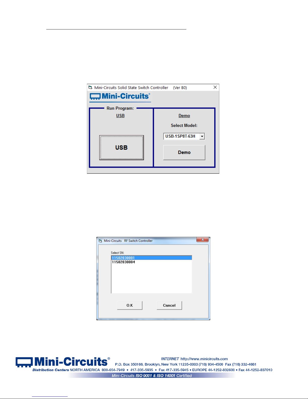
3.1.2 To run a demo of a solid state switch select the model from the drop down menu
and click DEMO, otherwise click USB to start.
3.1.3 If multiple switches are connected to the computer, the initial scr een will
show a list of S/N for connected units. Select the unit y ou wish to start with and click OK, or
click Cancel to exit the program. The program can handle up to 24 units connected
simultaneously.
Figure 3.1.3: Unit selection screen
Figure 3.1.1: Initial screen
Page 15 of 23
AN-49-012 Rev.: (January 10, 2019) M171660 (R94356) File: AN-49-012(B).doc
This document and its contents are the property of Mini-Circuits
Page 16
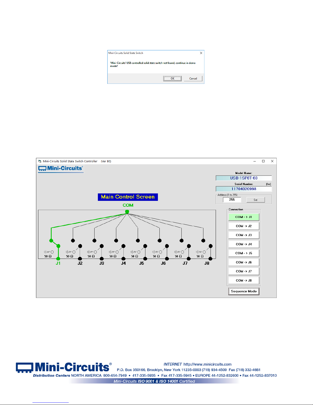
3.1.4 If no switch modules are connected to the computer via USB, or there is a
problem with the power or USB connection of the unit an alert will pop up. Click OK, then
check the power and USB connections of the unit bef or e trying again.
Figure 3.1.4: No USB Unit found
3.1.5 Once the GUI is started you can:
•
Click on the switch setting you wish to use
•
Use the Sequence mode to set a timed switching sequence (see section 3.2 )
•
Select the (fw) indicator to upgrade the firmware (S ee section 3.3)
•
Update the unit address by entering an integer in the 1-255 range in the Address
field below the S/N and clicking Set.
Figure 3.1.5 Main screen
Page 16 of 23
AN-49-012 Rev.: (January 10, 2019) M171660 (R94356) File: AN-49-012(B).doc
This document and its contents are the property of Mini-Circuits
Page 17
3.2 Sequence Mode
The GUI supports a “Sequence Mode” which allo ws the user to program a timed sequence of
switch states.
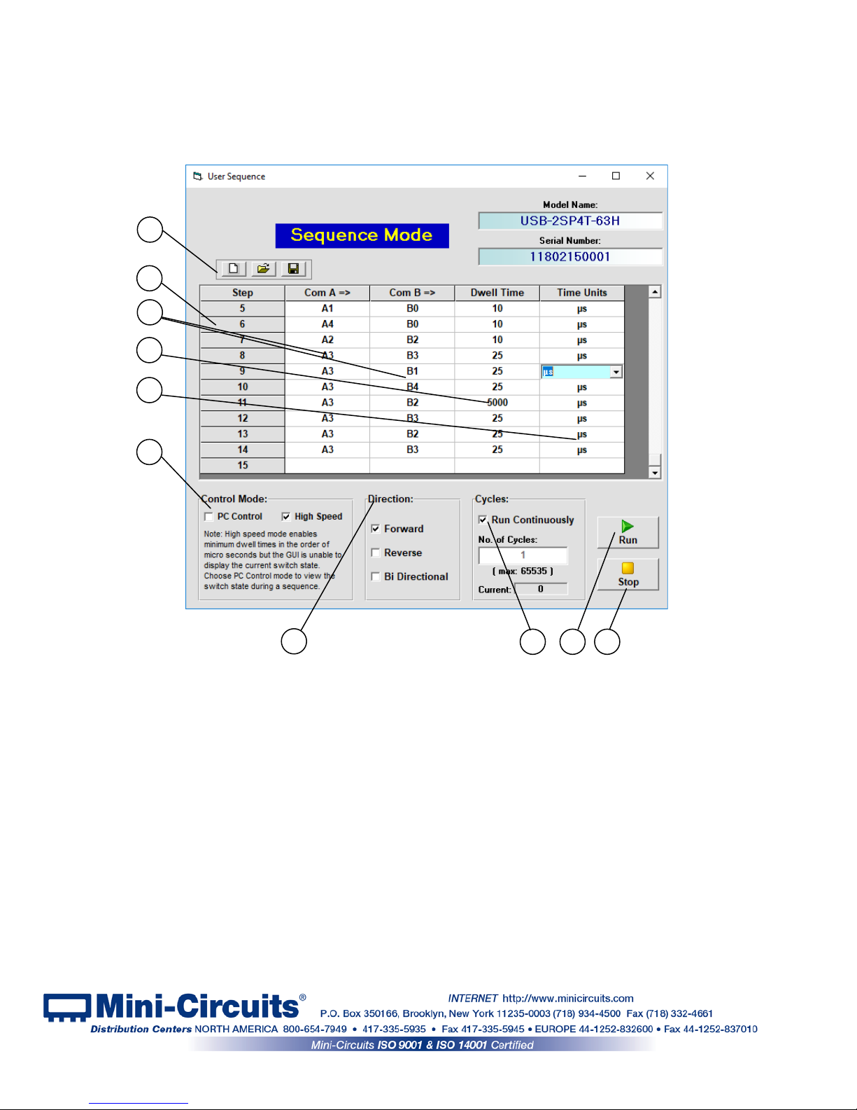
3.2.1 After clicking on the Sequence mode button, the User sequence
window will open.
Figure 3.2.1 Main screen
1
2
3
4
5
6
7
8
9
10
Page 17 of 23
AN-49-012 Rev.: (January 10, 2019) M171660 (R94356) File: AN-49-012(B).doc
This document and its contents are the property of Mini-Circuits
Page 18
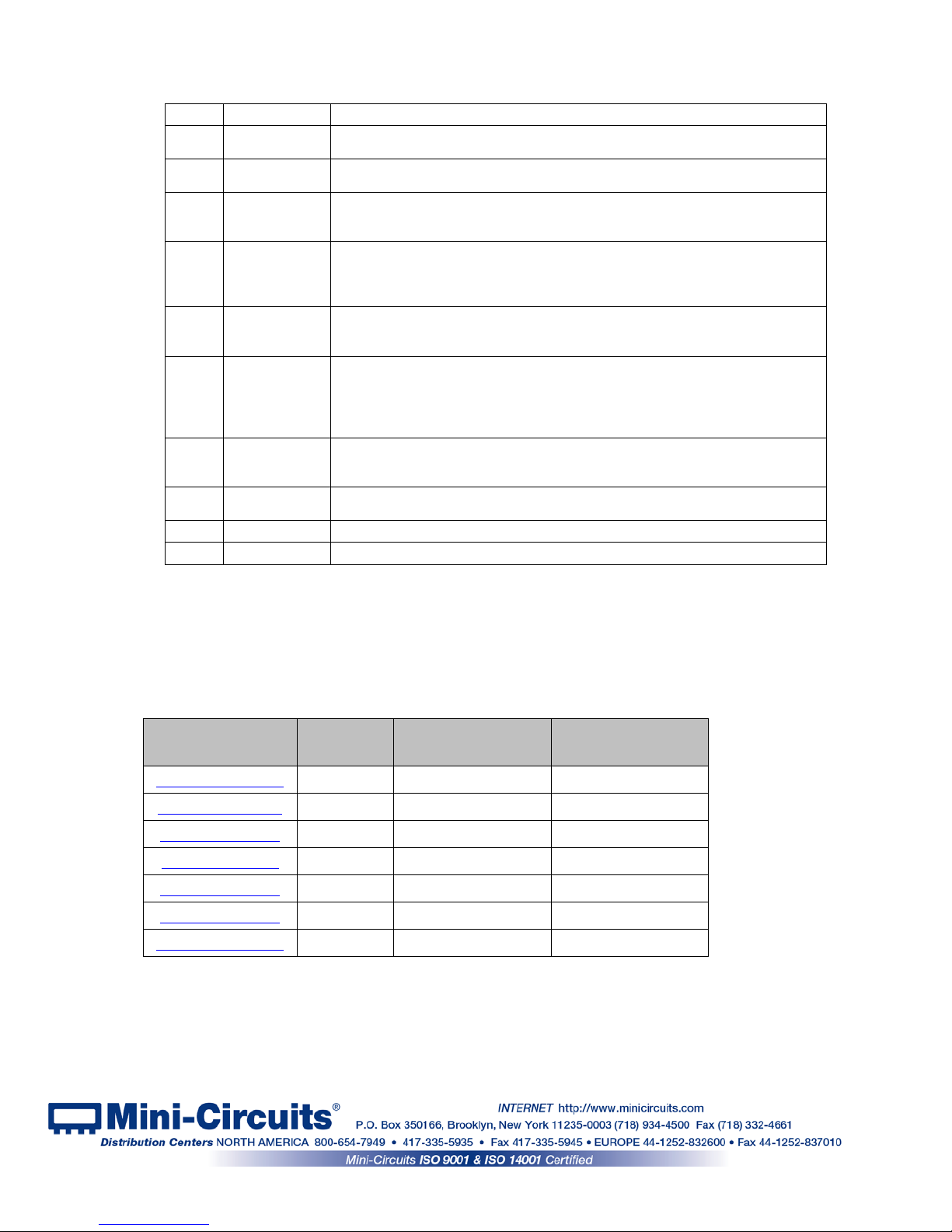
3.2.2 The user sequence controls are:
#
Name
Description
1
Icons
Allow clearing a current sequence, opening a previously saved sequenc e or
saving the current sequence.
2
Step
Listing of the step number in the sequence. Up to 100 steps in a sequence
are possible.
3
Com =>
The port to which the Com port connects in any given step, one column for
each switch in unit. In models with mul tiple switches all columns nee d to be
filled.
4
Dwell Time
The time the switch will hold at each step (must be an integer value). When
operating in high speed mode, note that some models have an additional
processing delay of a few microseconds , which should be subtracted from
the desired value to get accurate timing. See 3.2.4 for details.
5
Time units
The time units of the dwell time set in each step. The time units can be set
independently for each step to seconds, milliseconds or microseconds (in
high speed mode).
6
Control mode
Select between PC control (Each command is send individually from the PC
and status can be monitored) or High speed mode(the entire sequence is
sent in a single block of commands and triggered with an execute command
– allows for faster and more precise timing but status cannot be monitored
from the PC).
7
Direction
Select direction the sequence will run. Forward is the sequence as shown,
reverse will run the sequence from last step to first and bi-direction al will run
the sequence from first step to last, then from last step to first.
8
Cycles
Number of cycles to run, can be set from 1 to 65535. If “run continuously” is
selected the sequence will keep rep eating until stopped.
9
Run Start running the sequence with the current settings.
10
Stop
Stop the switch in the current setti ng
3.2.3 To delete a line click on the relevant step number and press ‘delete’. To run only a
single step, double click on the number of that step.
3.2.4 High speed mode is only available from certain firmware revision in each model.
See below table of models with the earliest revision that supports high speed mode, and the
typical processing delay for each model.
Model Name
Firmware
Revision
Processing delay
Typical Switch
transition time
U2C-1SP2T-63VH
B9 No processing delay 0.7 µs
USB-2SP2T-DCH
A5 10 µs 10 µs
USB-4SP2T-63H
A5 25 µs 0.2 µs
U2C-1SP4T-63H
B9 No processing delay 0.2 µs
USB-2SP4T-63H
A5 12 µs 5 µs
USB-1SP8T-63H
A5 10 µs 0.2 µs
USB-1SP16T-83H
A5 10 µs 5 µs
Page 18 of 23
AN-49-012 Rev.: (January 10, 2019) M171660 (R94356) File: AN-49-012(B).doc
This document and its contents are the property of Mini-Circuits
Page 19
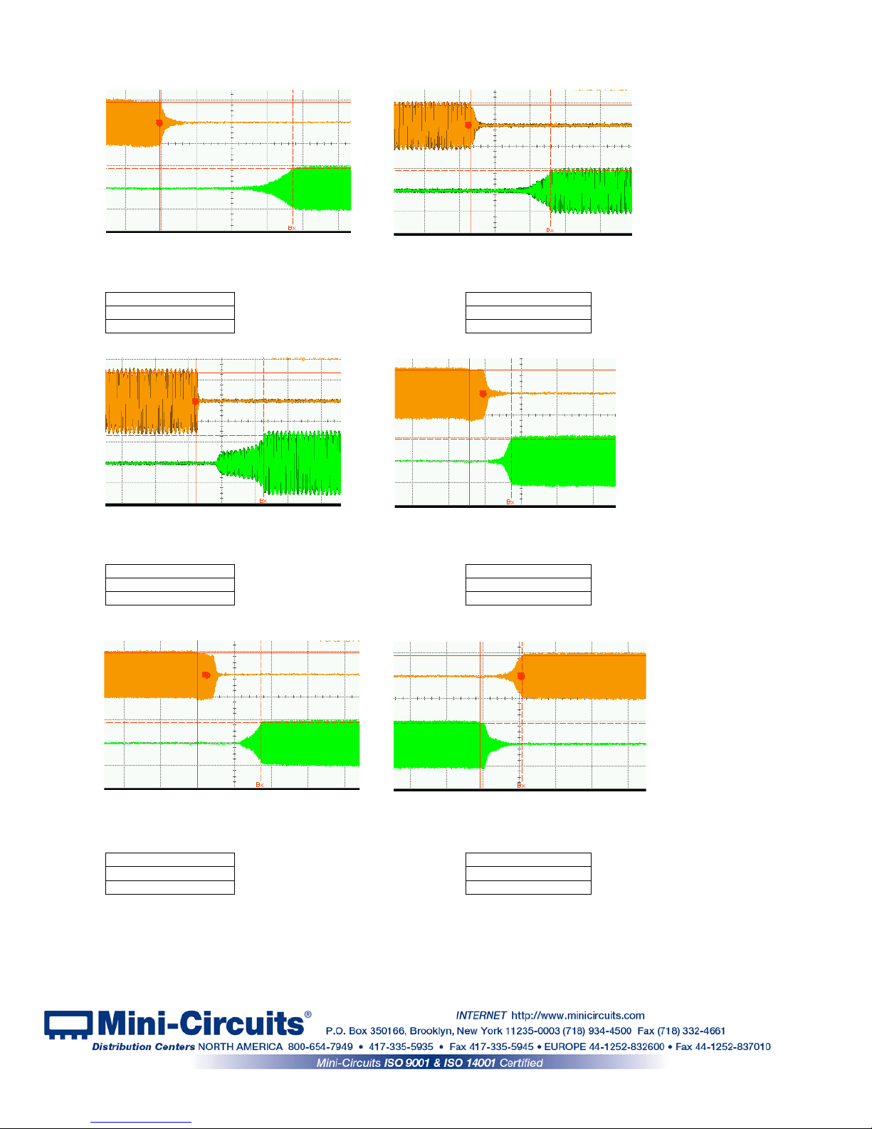
3.2.5 Typical transition speed plots:
Ax = 614.308 µs
Ax = 609.676 µs
Bx = 614.683 µs
Bx = 614.221 µs
Δx = 375 ns
Δx = 4.545 µs
Ax = 625.747 µs
Ax = 628.071 µs
Bx = 629.820 µs
Bx = 628.188 µs
Δx = 4.073 µs
Δx = 116 ns
Ax = 634.592 µs
Ax = 642.124 µs
Bx = 634.763 µs
Bx = 642.239 µs
Δx = 171 ns
Δx = 115 ns
Figure 3.2.5a: Typ. Switching time for
U2C-1SP2T-63VH with dwell time 5 µs
Figure 3.2.5b: Typ. Switching time for
USB-1SP16T-83H Port 1-Port 16 with
dwell time 15 µs
Figure 3.2.5c: Typ. Switching time for
USB-2SP4T-63H Port1-Port4 with
dwell time 15 µs
Figure 3.2.5d: Typ. Switching time for
U2C-1SP4T-63H Port1-Port4 with
dwell time 5 µs
Figure 3.2.5e: Typ. Switching time for
USB-1SP8T-63H Port1-Port8 with
dwell time 25 µs
Figure 3.2.5f: Typ. Switching time for
USB-1SP8T-63H Port1-Port2 with
dwell time 25 µs
Page 19 of 23
AN-49-012 Rev.: (January 10, 2019) M171660 (R94356) File: AN-49-012(B).doc
This document and its contents are the property of Mini-Circuits
Page 20
3.3 Firmware update & recovery
3.3.1 All units are shipped with the latest available firmware and an update is
usually not required. Mini-Circuits occasional l y makes firmware update files available as a
courtesy to add additional features or correct known issues. Please contact
testsolutions@minicircuits.com f or det ai l s.
3.3.2 Once the switch controller GUI is installed and started (see chapter 2) you
will note an (fw) indicator in the upper right corner of the main scr een.
Figure 3.3.2 Firmware indicator on main screen
3.3.3 In order to update your switch firmware, you must have a Windows
computer with Mini-Circuits’ Switch Controller software installed.
The firmware update process has the potential to render the device inoperable in the
event of communication failure. Updates should only be carried out with a stable PC and
USB connection, and in-line with Mini-Circuits guidelines.
A recovery option is available to restore units rendered inoperable by an incorrect
upgrade process. See section 3.3.8 for details
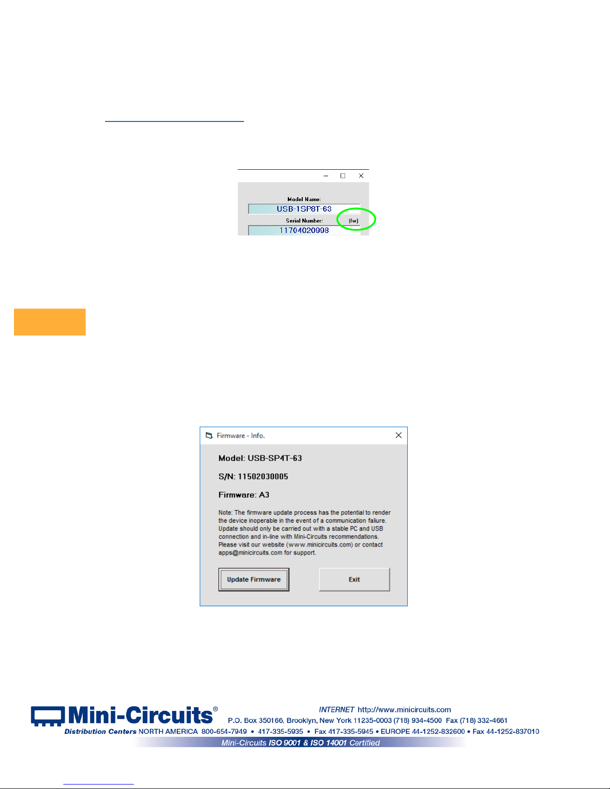
3.3.4 Click on the ‘(fw)’ indicator, this will cause the firmware - info window to open
(See Fig. 3.3.4). The ‘Firmware’ listed is the version of the firmware installed in your switch
matrix. Click on “Update Firmware” to select a new firmware version to install or click ‘Exit’ to
close the firmware – info window.
Figure 3.3.4: Firmware Information Window
CAUTION
Page 20 of 23
AN-49-012 Rev.: (January 10, 2019) M171660 (R94356) File: AN-49-012(B).doc
This document and its contents are the property of Mini-Circuits
Page 21
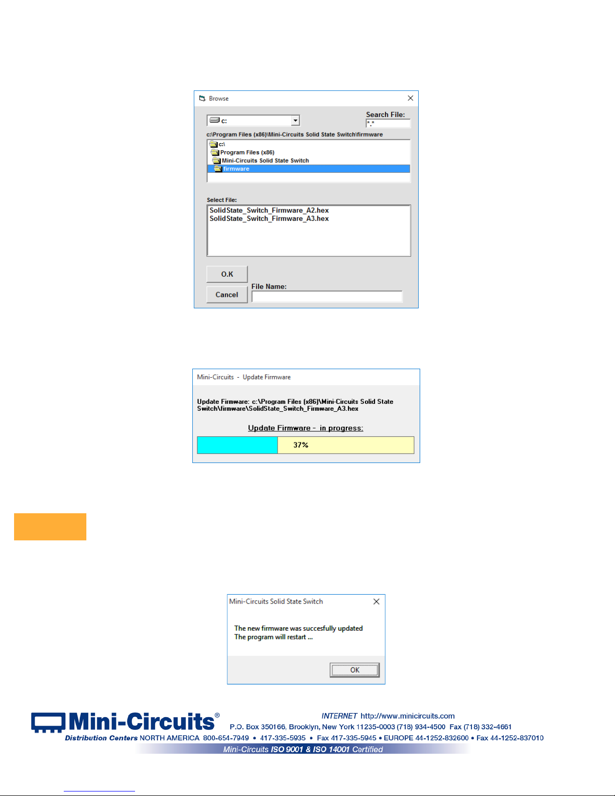
3.3.5 A browse window will open to the firmware directory under the path
you selected when installing the GUI program (See Fig. 3.3.5). Navigate to where you saved
your firmware file, Select the firmware version you wish to install an d cli ck ‘O.K’.
Figure 3.3.5: Firmware - Browse Window
3.3.6 The selected file will be installed in the switch the process will take up to a
minute.
Figure 3.3.6: Firmware - Progress Bar Window
Attempting to start a second GUI session while the firmware is being updated may cause
the firmware to be corrupted. It is therefore recommended not to attempt to start any
additional GUI sessions until after the firmware upgrade has been completed.
3.3.7 After the firmware has updated an alert will appear. Click ‘OK’ to shut down
the Switch Controller program and then restart it normally.
Figure 3.3.7: Firmware - Successful Update
CAUTION
Page 21 of 23
AN-49-012 Rev.: (January 10, 2019) M171660 (R94356) File: AN-49-012(B).doc
This document and its contents are the property of Mini-Circuits
Page 22
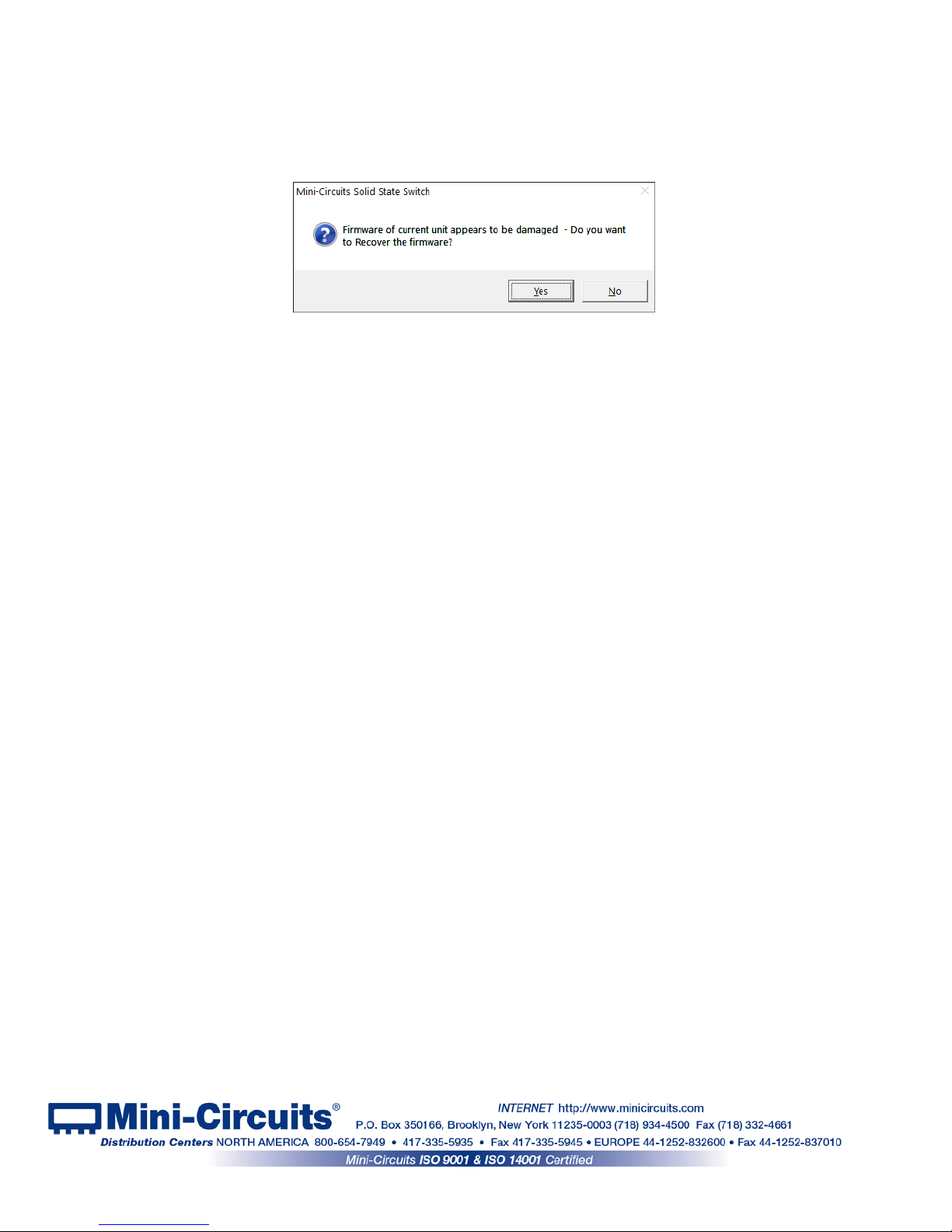
3.3.8 If the firmware upgrade was interrupted this can result in partial installation
rendering the device inoperable. When you attempt to connect a unit with damaged firmware
an alert (See Fig 3.3.8) will appear. Click ‘Yes’ to restart the firmware upgrade and repeat
the attempt to install the firmware, or ‘No’ to cancel.
Figure 3.3.8 Firmware recovery notice
Page 22 of 23
AN-49-012 Rev.: (January 10, 2019) M171660 (R94356) File: AN-49-012(B).doc
This document and its contents are the property of Mini-Circuits
Page 23

4 Chapter 4 – Revision history
August 31, 2017: Created user guide Rev OR.
June 05, 2018: Added USB-1SP16T-83H, U2C-1SP4T-63H, U2C-1SP2T-63VH. Added I
2
C, SPI &
TTL control methods.
January 10, 2019: Added USB-2SP4T-63H. Added description high speed swi tching mode and plots
of switching time for various models .
Page 23 of 23
AN-49-012 Rev.: (January 10, 2019) M171660 (R94356) File: AN-49-012(B).doc
This document and its contents are the property of Mini-Circuits
 Loading...