

Page 1
Mini-Circuits
USB / Ethernet
RoHS Compliant
See our web site for RoHS Compliance
methodologies and qualifications
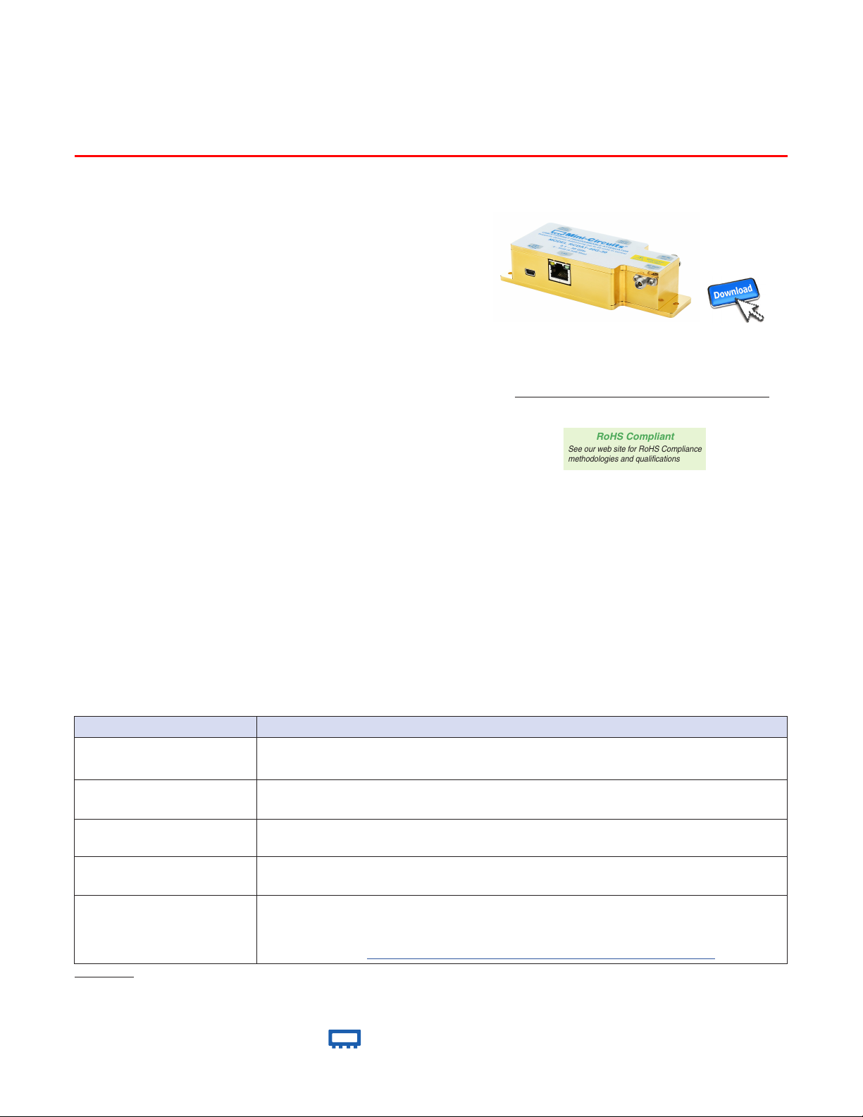
Programmable Attenuator
50Ω
0.1 to 40 GHz
RCDAT-40G-30
The Big Deal
• Precision attenuation up to 40 GHz
• Fine resolution, 0.5 dB
• Fast transitions, 100 ns
• USB and Ethernet control
• Control up to 25 attenuators via a single interface
via ‘Daisy Chain’ connection
Software Package
Case Style: MS2523
Applications
• Transmission loss simulation
• 5G network infrastructure
Model No. Description Qty.
MUSB-CBL-3+ 2.6 ft. USB cable 1
Included Accessories
• Microwave point to point links
• VHF / UHF / L / S / C / X / Ku / K band testing
Product Overview
Mini-Circuits’ RCDAT-40G-30 is a precision programmable attenuator covering an extremely wide bandwidth, from
0.1 to 40 GHz. Its unique design allows attenuation settings to be programmed from 0 to 30 dB, in 1.0 dB steps
(Mode 1) and 0 to 29 dB in 0.5 dB steps (Mode 2) with monotonic attenuation change per dB, even at the highest
frequencies and attenuation settings.
The attenuator can be controlled via USB or Ethernet, allowing control directly from a PC, or remotely over a
network. Full software support is provided, including our user-friendly GUI application for Windows and a full API
with programming instructions for Windows and Linux environments (both 32-bit and 64-bit systems).
This model also includes Mini-Circuits’ novel dynamic addressing daisy-chaining interface which allows multiple
RCDAT-40G-30 attenuators to be connected together into a Master / Slave chain, with independent control of each
attenuator channel through the single USB or Ethernet connection of the master unit.
Key Features
Extremely wide bandwidth
Daisy chain control
(dynamic addressing)
USB & Ethernet control
Programmable attenuation
sweep and Hop sequences
Full software support
Trademarks: Windows is a registered trademark of Microsoft Corporation in the United States and other countries. Linux is a registered trademark of Linus Torvalds. Mac is a registered trademark of Apple Corporation.
series attenuators are affiliated with or endorsed by the owners of the above referenced trademarks.
Mini-Circuits and the Mini-Circuits logo are registered trademarks of Scientific Components Corporation.
Feature Advantages
A single attenuator covers a diverse range of RF and microwave applications from 0.1 to 40 GHz
Simplify control software and interconnections by cascading up to twenty five modules
USB HID and Ethernet (HTTP / Telnet) interfaces provide easy compatibility with a wide range
of software setups and programming environments
The RCDAT-40G-30 can be programmed with a timed sequence of attenuation settings, to
run without any additional external control.
User friendly Windows GUI (graphical user interface) allows manual control straight out of
the box, while the comprehensive API (application programming interface) with examples
and instructions allows easy automation in most programming environments. For details and
download link see https://www.minicircuits.com/softwaredownload/patt.html
Pentium is a registered trademark of Intel Corporation.
®
www.minicircuits.com P.O. Box 350166, Brooklyn, NY 11235-0003 (718) 934-4500 sales@minicircuits.com
Neither Mini-Circuits nor the Mini-Circuits RCDAT-
Re v. B
ECO-005533
RCDAT-40G-30
RAV/MCL NY
201221
Page 1 of 13
Page 2

Mini-Circuits
USB / Ethernet Programmable Attenuator
RCDAT-40G-30
Electrical Specications1 at +25°C
Parameter Frequency range Conditions Min. Typ. Max. Units
Frequency range − − 0.1 − 40 GHz
8
Attenuation
range
Attenuation accuracy
Insertion Loss
Isolation In-Out 0.1 - 40 GHz Note 2 − 40 − dB
Input operating power
(RF In or RF Out ports)
IP3 Input
VSWR 0.1 - 40 GHz @ 0 - 30 dB − 1.50 − :1
Min Dwell Time
Attenuation Transition Time
Supply Voltage − via USB or serial control 4.75 5 5.25 V
DC current draw
1
Attenuator RF ports are interchangeable, and support simultaneous, bidirectional signal transmission, however the specifications are guaranteed for the RF In and
RF Out as noted on the label. There may be minor changes in performance when injecting signals to the RF Out port.
2
Isolation is defined as max attenuation plus insertion loss; this is the path loss through the attenuator when initially powered up. After a brief delay (~0.5 sec typically) the
attenuator will revert to a user defined “power-up” state (either max attenuation or a pre-set value).
3
Total operating input power on RF In or RF Out ports to bring the attenuator to about 0.1dB compression.
4
Tested with 1 MHz offset between signals.
5
Minimum Dwell Time is the time the RCDAT will take to respond to a command to change attenuation states without communication delays. In PC control mode
add communication delays (on the order of ms for USB) to get actual response time.
6
Attenuation Transition Time is specified as the time between starting to change the attenuation state and settling on the requested attenuation state.
7
DC current consumption shown for a single attenuator, without any slaves connected in series.
8
Attenuation range in Mode 1 operation is 30 dB with 1 dB step.
9
Attenuation range in Mode 2 operation is 29 dB with 0.5 dB step.
Mode 1
9
Mode 2
3
4
5
6
7
0.1 - 40 GHz
0.1 - 8 GHz
8 - 16 GHz
16 - 24 GHz
24 - 32 GHz
32 - 40 GHz
0.1 - 8 GHz
8 - 16 GHz − 9.0 11.0
16 - 24 GHz 12.0 15.0
24 - 32 GHz − 14.0 16.0
32 - 40 GHz − 14.0 16.0
0.1 - 40 GHz @ 0 - 30 dB − − 24 dBm
0.1 - 40 GHz
0.1 - 40 GHz High speed mode − 600 − µs
0.1 - 40 GHz − − 100 − ns
− Ethernet Enabled − 400 450
− Ethernet Disabled 250 300
1 dB step
0.5 dB step 29
@ 0.5 - 8 dB − ±0.5 −
@ 8.5 - 30 dB − ±1.0 −
@ 0.5 - 8 dB − ±0.5 −
@ 8.5 - 30 dB − ±1.0 −
@ 0.5 - 8 dB − ±1.0 −
@ 8.5 - 30 dB − ±1.5 −
@ 0.5 - 8 dB − ±1.0 −
@ 8.5 - 30 dB − ±2.0 −
@ 0.5 - 8 dB − ±1.0 −
@ 8.5 - 30 dB − ±1.5 −
@ 0 dB
@ 0 dB setting
(PIN=+5 dBm)
0 −
− 6.0 8.0
− +38 − dBm
30
dB
dB
dB
mA
Absolute Maximum Ratings
Operating Temperature 0°C to 50°C
Storage Temperature -20°C to 85°C
V
Max. 6V
USB
Total RF power for RF In & RF Out +35 dBm
DC voltage at RF port +25V
Permanent damage may occur if any of these limits are exceeded.
Operating in the range between operating power limits and absolute
maximum ratings for extended periods of time may result in reduced
life and reliability.
www.minicircuits.com P.O. Box 350166, Brooklyn, NY 11235-0003 (718) 934-4500 sales@minicircuits.com
Connections
RF In (2.92mm female)
RF Out (2.92mm female)
USB (USB type Mini-B female)
Network (Ethernet/LAN) (RJ45 socket)
Serial Control Out (10 Pin Digital Snap Fit female)
Serial Control In (10 Pin Digital Snap Fit female)
8
Mating connector is Hirose ST40X-10S-CV(30)
®
8
8
Page 2 of 13
Page 3
Mini-Circuits
USB / Ethernet Programmable Attenuator
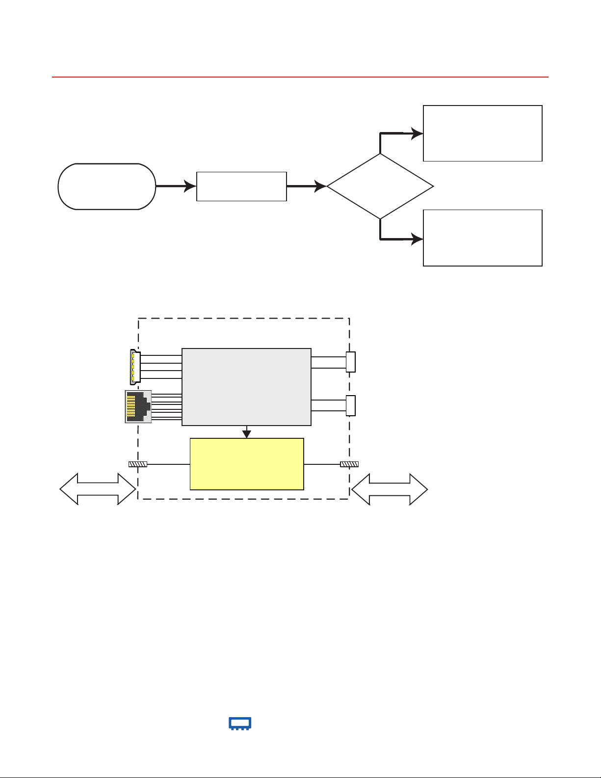
RCDAT response to communication interrupt
YES
RCDAT-40G-30
RCDAT will shut down.
Once power is reconnected
it will restart according to
the conditions previously
defined by user
Start RCDAT in
either USB or
Ethernet control
Communication is
interrupted*
* Can be due to a software glitch in the controlling PC or a physical
disconnect of the control lines
Block Diagram
USB
MICROCONTROLLER
RJ45
(Ethernet)
RF Out
50Ω
MICROCONTROLLER
Control
Control
Control
Digital Step
Attenuator
Is power supply
interrupted?
NO
Serial
Ctrl Out
Serial
Ctrl In
RF In
50Ω
RCDAT will maintain last
state set until
communication is
reestablished via either
control method
Simultaneous, bidirectional RF signal transmission with symmetrical performance
For ethernet control shielded ethernet cable is recommended
®
www.minicircuits.com P.O. Box 350166, Brooklyn, NY 11235-0003 (718) 934-4500 sales@minicircuits.com
Page 3 of 13
Page 4
Mini-Circuits
USB / Ethernet Programmable Attenuator
RCDAT-40G-30
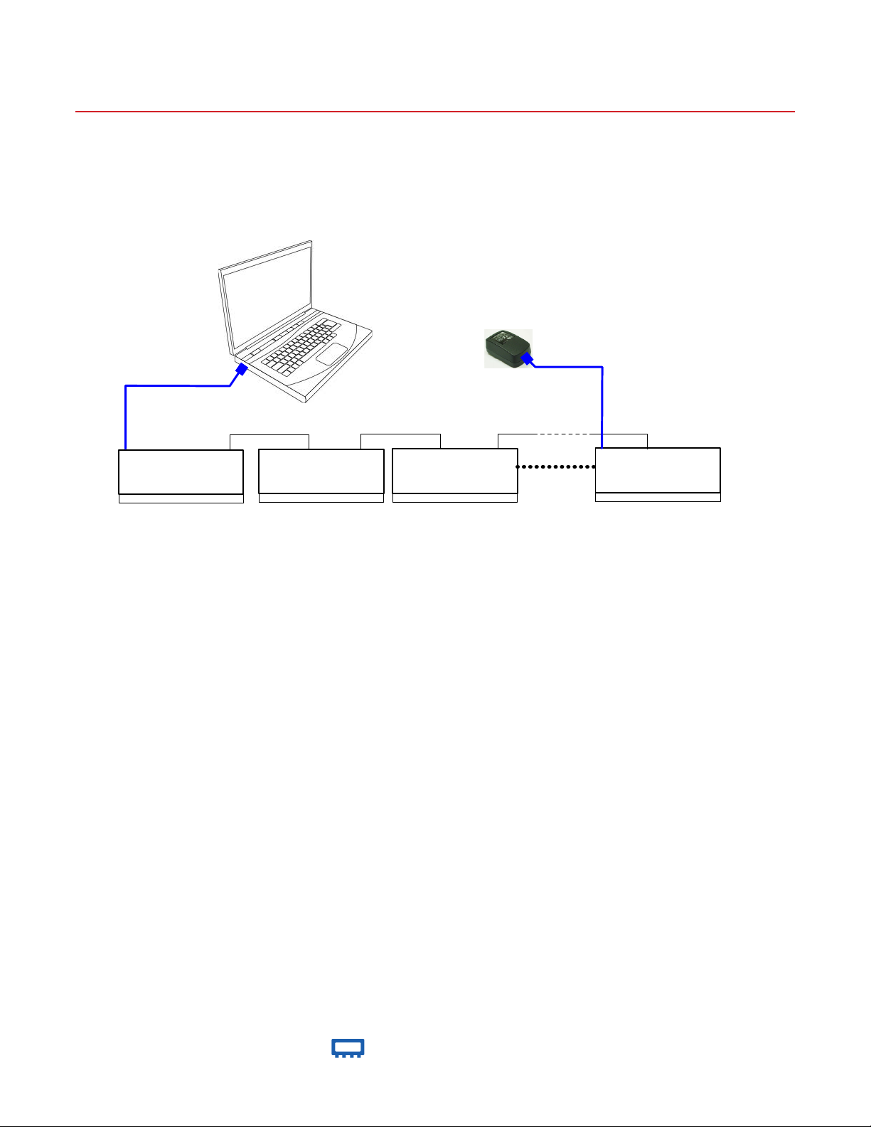
Connecting multiple modules (Daisy Chain)
The RCDAT-40G-30 is designed to connect up to 25 modules in series (Daisy chain) using dynamic addressing, meaning there is no
need to specifically set the address of the modules, the addresses will be set automatically as part of establishing the communications
with the PC. The module connected to the PC USB port or LAN connection will be assigned address 0 (Master), the first module
connected to it will get address 1(slave) and subsequent modules incrementing up to address 24 (slave).
USB control
(limited to 500mA max)
USB Serial Ctrl In Serial Ctrl Out
RCDAT-40G-30 (Module 0)
RF Connectors
Master
USB Serial Ctrl In Serial Ctrl Out
RCDAT-40G-30 (Module 1)
RF Connectors
Slave 1
power adaptor
USB Serial Ctrl In Serial Ctrl Out
RCDAT-40G-30 (Module 2)
RF Connectors
Slave 2
Additional power supplies need to
be connected every two modules if
Ethernet is enabled or every three
modules if Ethernet is disabled.
USB Serial Ctrl In Serial Ctrl Out
RCDAT-40G-30 (Module 24)
RF Connectors
Slave 24
Connections between modules will be made using the serial in/out ports with the module connected to the PC as a master and all
other as slave modules. All control will be through the master module (address zero) which is the only one communicating with the
PC (via USB or Ethernet). Serial control out port of each module should be connected to the serial control in port of the next module.
Power can be supplied from the PC via the master module or from additional power supplies connected to the USB ports of slave units.
Note that with Ethernet enabled each unit will draw up to 450 mA so to connect three units in series you will need to supply 1350mA,
thus it is recommended to turn off the Ethernet circuitry in the slave units to reduce the power requirements. Connecting an additional
power supply will automatically cut off power draw from the serial control in port for the module connected.
The Serial master/slave bus allows connecting modules of different types to the same daisy chain as long as all support Mini-Circuits
dynamic addressing setup. To add a new module to the set up simply connect the module to the setup and refresh the address listing,
no need to reset any of the existing modules or assign addresses manually.
Note: Different module types may have different current consumption which will change the number of units which can be connected
before additional power supply is needed.
®
www.minicircuits.com P.O. Box 350166, Brooklyn, NY 11235-0003 (718) 934-4500 sales@minicircuits.com
Page 4 of 13
Page 5
Mini-Circuits
USB / Ethernet Programmable Attenuator
RCDAT-40G-30
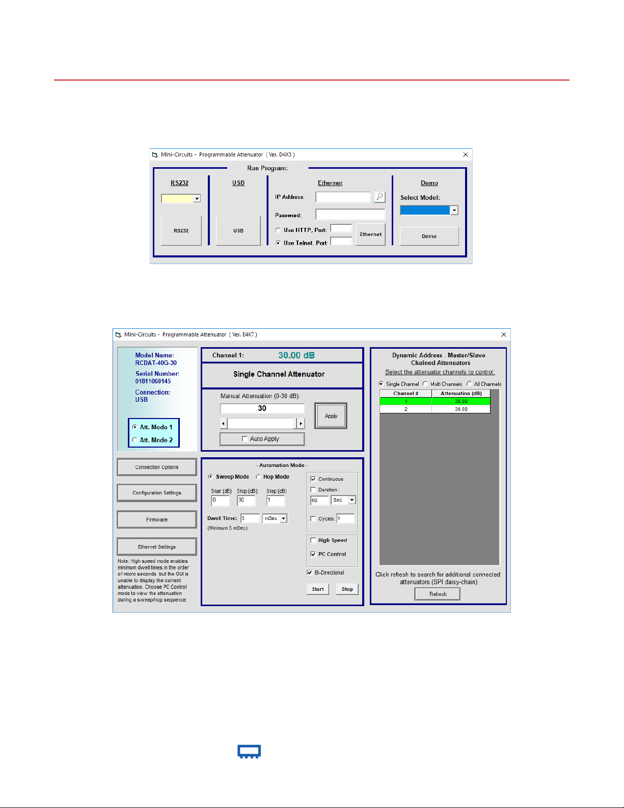
Controling multiple modules in GUI program
Connect the attenuator you wish to use as master to either USB or LAN and connect additional units to the master using the serial
control in/out ports and CBL-1.5FT-MMD+ or equivalent control cables, then start the GUI and select the control method you wish to
use (USB, HTTP or Telnet, RS232 is not available in this model)
RCDAT-40G-30
RCDAT GUI initial (control selection) screen
Once you’ve selected the control method the main attenuation control screen will appear, allowing you to set a fixed attenuation, an
arbitrary sequence of attenuation steps, or a sweep(ramp) of attenuation for each attenuator, or for a number of attenuators at once.
RCDAT GUI main screen (USB control) with 2 units connected in series
®
www.minicircuits.com P.O. Box 350166, Brooklyn, NY 11235-0003 (718) 934-4500 sales@minicircuits.com
Page 5 of 13
Page 6

Mini-Circuits
USB / Ethernet Programmable Attenuator
RCDAT-40G-30
RCDAT GUI main screen (USB control) with 2 units connected in series
®
www.minicircuits.com P.O. Box 350166, Brooklyn, NY 11235-0003 (718) 934-4500 sales@minicircuits.com
Page 6 of 13
Page 7

Mini-Circuits
USB / Ethernet Programmable Attenuator
RCDAT-40G-30
Outline Drawing (MS2523)
Connections
RF In (2.92mm female)
RF Out (2.92mm female)
USB (USB type Mini-B female)
Network (Ethernet/LAN) (RJ45 socket)
Serial Control Out (10 Pin Digital Snap Fit female)
8
Mating connector is Hirose ST40X-10S-CV(30)
8
inch
mm
ABCDEFGHJKLMNPQR ST Uwt
4.00 1.75 0.92 -- -- -- -- 0.30 0.72 4.75 0.52 1.20 4.40 0.18 0.28 0.38 0.87 0.67 0.12 grams
101.60 44.45 23.49 -- -- -- -- 7.54 18.19 120.65 13.11 30.45 111.76 4.45 6.99 9.53 22.20 17.06 3.00 520.0
®
www.minicircuits.com P.O. Box 350166, Brooklyn, NY 11235-0003 (718) 934-4500 sales@minicircuits.com
Page 7 of 13
Page 8

Mini-Circuits
USB / Ethernet Programmable Attenuator
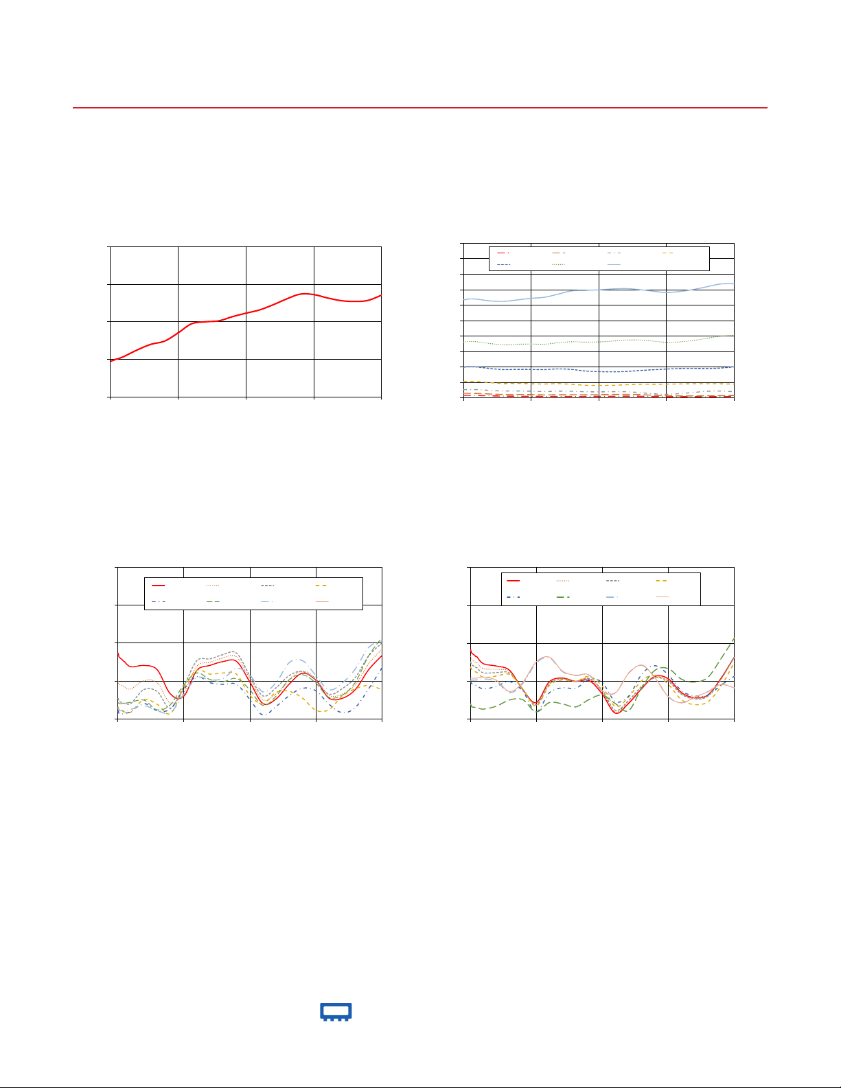
Typical Performance Curves @+25°C (Mode 1)
RCDAT-40G-30
RCDAT-40G-30
Insertion Loss
20
15
10
Insertion Loss (dB)
5
0
0 10000 20000 30000 40000
Frequency (MHz)
3.0
Input VSWR over Attenuation settings
2.5
RCDAT-40G-30
0 dB 1.0 dB 2.0 dB 4.0 dB
8.0 dB 16 dB 30 dB
Attenuation relative to Insertion Loss over
50
45
40
35
30
25
20
Attenuation (dB)
15
10
3.0
2.5
1.0 dB 2.0 dB 4.0 dB 8.0 dB 16 dB 30 dB
5
0
0 10000 20000 30000 40000
Output VSWR over Attenuation settings
0 dB 1.0 dB 2.0 dB 4.0 dB
8.0 dB 16 dB 30 dB
RCDAT-40G-30
Attenuation settings
Frequency (MHz)
RCDAT-40G-30
2.0
VSWR (:1)
1.5
1.0
0 10000 20000 30000 40000
Frequency (MHz)
www.minicircuits.com P.O. Box 350166, Brooklyn, NY 11235-0003 (718) 934-4500 sales@minicircuits.com
2.0
VSWR (:1)
1.5
1.0
0 10000 20000 30000 40000
Frequency (MHz)
®
Page 8 of 13
Page 9

Mini-Circuits
USB / Ethernet Programmable Attenuator
Typical Performance Data @ +25°C (Mode 1)
Frequency Insertion Attenuation relative to Insertion Loss
(GHz) Loss (dB)
(dB) @ Attenuation setting
0 dB 1 dB 2 dB 4 dB 8 dB 16 dB 30 dB
100 5.53 1.31 2.45 4.46 9.07 17.24 30.45
200 5.57 1.31 2.45 4.46 9.15 17.28 30.48
300 5.61 1.32 2.45 4.46 9.17 17.29 30.45
400 5.64 1.32 2.46 4.47 9.19 17.31 30.51
500 5.67 1.32 2.46 4.47 9.20 17.34 30.56
600 5.71 1.32 2.47 4.48 9.22 17.36 30.63
700 5.75 1.31 2.47 4.49 9.23 17.38 30.67
800 5.78 1.31 2.48 4.50 9.25 17.43 30.77
900 5.81 1.31 2.48 4.50 9.25 17.44 30.78
1000 5.82 1.32 2.48 4.50 9.24 17.40 30.70
2000 6.13 1.28 2.48 4.49 9.21 17.38 30.69
4000 6.88 1.11 2.28 4.24 8.82 16.90 30.27
6000 7.53 0.97 2.11 4.06 8.58 16.61 30.25
8000 7.91 0.94 2.12 4.11 8.68 16.81 30.72
10000 8.75 0.89 2.06 4.05 8.67 16.90 31.29
12000 9.89 0.81 1.99 4.03 8.68 16.88 31.65
14000 10.35 0.83 2.08 4.13 8.88 17.35 32.66
16000 10.56 0.83 2.08 3.92 8.72 17.68 33.68
18000 11.31 0.82 1.96 3.58 8.21 17.58 33.83
20000 12.00 0.82 1.92 3.51 7.98 17.61 33.97
22000 12.49 0.85 1.98 3.53 7.89 17.83 34.23
24000 13.17 0.88 1.99 3.66 7.96 18.14 34.33
26000 13.97 0.80 1.79 3.85 8.30 18.19 34.02
28000 14.70 0.61 1.43 3.94 8.62 17.91 33.67
30000 14.75 0.48 1.25 4.02 8.91 17.61 33.34
32000 14.26 0.43 1.45 4.13 9.12 17.74 33.78
34000 13.90 0.44 1.80 4.19 9.14 18.19 34.45
36000 13.68 0.47 2.14 4.20 9.10 18.87 35.36
38000 13.81 0.52 2.23 4.17 9.23 19.57 36.20
40000 14.52 0.55 2.03 4.00 9.59 19.78 36.20
RCDAT-40G-30
Frequency VSWR In VSWR Out
(GHz) (:1) (:1)
@ Attenuation setting @ Attenuation setting
0 dB 1 dB 2 dB 4 dB 8 dB 16 dB 30 dB 0 dB 1 dB 2 dB 4 dB 8 dB 16 dB 30 dB
100 1.51 1.13 1.11 1.11 1.21 1.13 1.65 1.84 1.69 1.64 1.49 1.20 1.51 1.53
200 1.47 1.08 1.06 1.07 1.20 1.11 1.64 1.81 1.66 1.61 1.47 1.17 1.51 1.54
300 1.46 1.06 1.05 1.06 1.20 1.11 1.64 1.80 1.65 1.61 1.46 1.16 1.51 1.54
400 1.46 1.05 1.04 1.06 1.20 1.11 1.63 1.79 1.65 1.60 1.46 1.16 1.51 1.54
500 1.46 1.05 1.04 1.06 1.20 1.11 1.63 1.79 1.64 1.60 1.46 1.15 1.51 1.54
600 1.45 1.05 1.04 1.06 1.20 1.11 1.63 1.78 1.64 1.59 1.45 1.15 1.51 1.54
700 1.44 1.05 1.05 1.06 1.20 1.11 1.63 1.78 1.64 1.59 1.45 1.15 1.51 1.54
800 1.44 1.05 1.05 1.06 1.20 1.11 1.63 1.78 1.63 1.59 1.45 1.15 1.51 1.54
900 1.43 1.04 1.05 1.07 1.21 1.11 1.63 1.77 1.63 1.58 1.45 1.15 1.51 1.54
1000 1.43 1.04 1.05 1.07 1.21 1.11 1.63 1.77 1.63 1.58 1.44 1.15 1.52 1.54
2000 1.39 1.09 1.10 1.09 1.22 1.12 1.64 1.71 1.56 1.52 1.39 1.13 1.53 1.55
4000 1.47 1.34 1.27 1.20 1.24 1.17 1.58 1.69 1.58 1.54 1.43 1.17 1.49 1.51
6000 1.46 1.30 1.19 1.10 1.12 1.11 1.40 1.68 1.60 1.58 1.50 1.25 1.35 1.36
8000 1.24 1.14 1.16 1.13 1.18 1.08 1.56 1.47 1.40 1.40 1.37 1.25 1.47 1.48
10000 1.31 1.50 1.51 1.38 1.44 1.31 1.83 1.20 1.18 1.17 1.09 1.09 1.74 1.75
12000 1.67 1.82 1.75 1.56 1.61 1.54 1.86 1.51 1.46 1.44 1.35 1.22 1.81 1.82
14000 1.72 1.83 1.69 1.48 1.52 1.52 1.67 1.60 1.53 1.52 1.42 1.20 1.62 1.63
16000 1.69 1.89 1.69 1.45 1.49 1.53 1.59 1.45 1.50 1.50 1.40 1.16 1.57 1.57
18000 1.70 1.91 1.67 1.45 1.53 1.66 1.52 1.40 1.55 1.58 1.52 1.25 1.58 1.58
20000 1.47 1.60 1.39 1.26 1.38 1.58 1.28 1.30 1.40 1.46 1.49 1.32 1.37 1.37
22000 1.20 1.34 1.24 1.05 1.18 1.36 1.22 1.08 1.12 1.18 1.23 1.21 1.34 1.34
24000 1.30 1.45 1.40 1.16 1.30 1.48 1.39 1.13 1.25 1.30 1.30 1.10 1.60 1.60
26000 1.48 1.61 1.45 1.30 1.52 1.74 1.44 1.30 1.44 1.52 1.59 1.42 1.72 1.71
28000 1.59 1.65 1.35 1.41 1.58 1.77 1.28 1.44 1.54 1.57 1.71 1.65 1.55 1.54
30000 1.51 1.52 1.17 1.37 1.47 1.57 1.07 1.37 1.49 1.45 1.59 1.67 1.30 1.29
32000 1.36 1.35 1.12 1.19 1.28 1.38 1.11 1.09 1.32 1.25 1.37 1.53 1.21 1.21
34000 1.50 1.43 1.30 1.08 1.31 1.47 1.24 1.18 1.26 1.19 1.31 1.49 1.29 1.29
36000 1.69 1.57 1.41 1.14 1.48 1.65 1.34 1.34 1.30 1.23 1.32 1.56 1.36 1.36
38000 2.06 1.88 1.51 1.40 1.84 1.96 1.45 1.54 1.52 1.44 1.45 1.80 1.45 1.45
40000 2.32 2.06 1.48 1.68 2.09 2.04 1.45 1.81 1.83 1.76 1.57 2.08 1.41 1.41
®
www.minicircuits.com P.O. Box 350166, Brooklyn, NY 11235-0003 (718) 934-4500 sales@minicircuits.com
Page 9 of 13
Page 10
Mini-Circuits
USB / Ethernet Programmable Attenuator
Typical Performance Curves @+25°C (Mode 2)
RCDAT-40G-30
RCDAT-40G-30
Insertion Loss
20
15
10
Insertion Loss (dB)
5
0
0 10000 20000 30000 40000
Frequency (MHz)
RCDAT-40G-30
3.0
2.5
Input VSWR over Attenuation settings
0 dB 0.5 dB 1.0 dB 2.0 dB
4.0 dB 8.0 dB 16 dB 29 dB
Attenuation relative to Insertion Loss over
50
45
40
35
30
25
20
Attenuation (dB)
15
10
5
0
0 10000 20000 30000 40000
3.0
2.5
0.5 dB 1.0 dB 2.0 dB 4.0 dB
8.0 dB 16 dB 29 dB
Output VSWR over Attenuation settings
0 dB 0.5 dB 1.0 dB 2.0 dB
4.0 dB 8.0 dB 16 dB 29 dB
RCDAT-40G-30
Attenuation settings
Frequency (MHz)
RCDAT-40G-30
2.0
VSWR (:1)
1.5
1.0
0 10000 20000 30000 40000
Frequency (MHz)
www.minicircuits.com P.O. Box 350166, Brooklyn, NY 11235-0003 (718) 934-4500 sales@minicircuits.com
2.0
VSWR (:1)
1.5
1.0
0 10000 20000 30000 40000
Frequency (MHz)
®
Page 10 of 13
Page 11

Mini-Circuits
USB / Ethernet Programmable Attenuator
Typical Performance Data @ +25°C (Mode 2)
Frequency Insertion Attenuation relative to Insertion Loss
(GHz) Loss (dB)
(dB) @ Attenuation setting
0 dB 0.5 dB 1 dB 2 dB 4 dB 8 dB 16 dB 29 dB
100 4.72 0.75 1.41 2.58 5.21 9.82 17.99 31.66
200 4.75 0.75 1.42 2.58 5.21 9.90 18.03 31.69
300 4.79 0.75 1.42 2.59 5.22 9.92 18.03 31.66
400 4.83 0.75 1.42 2.59 5.22 9.94 18.06 31.71
500 4.86 0.75 1.42 2.59 5.22 9.96 18.09 31.77
600 4.90 0.75 1.42 2.60 5.23 9.97 18.11 31.82
700 4.93 0.75 1.41 2.60 5.23 9.97 18.12 31.86
800 4.97 0.74 1.41 2.61 5.24 9.99 18.16 31.94
900 5.01 0.74 1.41 2.61 5.24 9.99 18.17 31.96
1000 5.00 0.75 1.42 2.61 5.25 10.00 18.14 31.91
2000 5.34 0.71 1.37 2.60 5.20 9.93 18.09 31.85
4000 6.23 0.59 1.18 2.35 4.83 9.41 17.49 31.29
6000 6.98 0.50 1.04 2.16 4.56 9.08 17.10 31.15
8000 7.39 0.48 1.03 2.16 4.59 9.16 17.28 31.61
10000 8.49 0.45 0.99 2.08 4.50 9.13 17.35 32.12
12000 9.71 0.41 0.91 2.00 4.44 9.10 17.28 32.46
14000 9.98 0.41 0.94 2.09 4.54 9.29 17.75 33.46
16000 10.10 0.42 0.96 2.07 4.33 9.14 18.08 34.52
18000 10.65 0.42 0.96 1.93 4.00 8.63 17.98 34.68
20000 11.12 0.44 0.97 1.87 3.95 8.43 18.03 34.86
22000 11.55 0.47 1.03 1.92 4.00 8.35 18.28 35.14
24000 12.24 0.50 1.08 1.92 4.16 8.46 18.63 35.27
26000 13.02 0.48 1.00 1.67 4.33 8.78 18.65 34.93
28000 13.66 0.40 0.79 1.27 4.34 9.03 18.29 34.45
30000 13.61 0.34 0.63 1.10 4.35 9.25 17.93 33.99
32000 13.17 0.32 0.56 1.32 4.45 9.44 18.03 34.33
34000 12.80 0.32 0.57 1.70 4.51 9.46 18.48 34.97
36000 12.69 0.32 0.61 2.05 4.52 9.42 19.17 35.85
38000 12.82 0.34 0.67 2.14 4.51 9.57 19.88 36.74
40000 13.52 0.37 0.72 1.92 4.37 9.96 20.12 36.85
RCDAT-40G-30
Frequency VSWR In VSWR Out
(GHz) (:1) (:1)
@ Attenuation setting @ Attenuation setting
0 dB 0.5 dB 1 dB 2 dB 4 dB 8 dB 16 dB 29 dB 0 dB 0.5 dB 1 dB 2 dB 4 dB 8 dB 16 dB 29 dB
100 1.87 1.49 1.27 1.15 1.11 1.21 1.13 1.79 1.92 1.83 1.75 1.69 1.49 1.20 1.51 1.54
200 1.82 1.46 1.23 1.12 1.07 1.20 1.11 1.78 1.88 1.79 1.72 1.66 1.47 1.17 1.51 1.54
300 1.81 1.45 1.23 1.11 1.06 1.20 1.11 1.77 1.87 1.78 1.71 1.65 1.46 1.16 1.51 1.54
400 1.80 1.45 1.22 1.11 1.06 1.20 1.11 1.76 1.86 1.77 1.71 1.64 1.46 1.16 1.51 1.54
500 1.79 1.44 1.22 1.11 1.06 1.20 1.11 1.76 1.85 1.77 1.70 1.64 1.46 1.16 1.51 1.54
600 1.79 1.44 1.22 1.10 1.06 1.20 1.11 1.76 1.85 1.76 1.70 1.63 1.45 1.16 1.51 1.54
700 1.78 1.44 1.21 1.10 1.06 1.20 1.11 1.76 1.84 1.76 1.69 1.63 1.45 1.15 1.51 1.54
800 1.77 1.43 1.21 1.10 1.06 1.20 1.11 1.76 1.83 1.75 1.68 1.62 1.45 1.15 1.51 1.54
900 1.76 1.43 1.21 1.09 1.07 1.20 1.11 1.76 1.82 1.74 1.68 1.62 1.44 1.15 1.51 1.54
1000 1.76 1.42 1.20 1.09 1.07 1.20 1.11 1.76 1.83 1.74 1.68 1.62 1.44 1.15 1.51 1.54
2000 1.68 1.39 1.20 1.08 1.09 1.22 1.12 1.76 1.73 1.66 1.61 1.55 1.40 1.13 1.53 1.55
4000 1.70 1.50 1.39 1.25 1.20 1.25 1.17 1.70 1.70 1.65 1.61 1.57 1.43 1.17 1.49 1.51
6000 1.65 1.48 1.36 1.19 1.11 1.12 1.11 1.50 1.64 1.63 1.60 1.59 1.49 1.25 1.35 1.36
8000 1.33 1.21 1.14 1.07 1.13 1.18 1.08 1.64 1.39 1.39 1.39 1.40 1.36 1.25 1.47 1.49
10000 1.29 1.34 1.42 1.40 1.38 1.44 1.31 1.93 1.22 1.20 1.18 1.17 1.09 1.09 1.74 1.75
12000 1.64 1.69 1.76 1.64 1.56 1.60 1.54 1.97 1.49 1.48 1.46 1.44 1.34 1.22 1.81 1.82
14000 1.70 1.74 1.79 1.59 1.47 1.52 1.51 1.76 1.54 1.54 1.52 1.51 1.41 1.20 1.62 1.63
16000 1.75 1.80 1.85 1.60 1.45 1.49 1.53 1.67 1.49 1.50 1.49 1.49 1.40 1.16 1.57 1.58
18000 1.76 1.82 1.87 1.59 1.45 1.53 1.67 1.60 1.51 1.52 1.54 1.56 1.52 1.26 1.58 1.58
20000 1.49 1.54 1.57 1.31 1.26 1.38 1.58 1.35 1.33 1.35 1.38 1.43 1.48 1.32 1.37 1.37
22000 1.20 1.25 1.30 1.20 1.05 1.18 1.35 1.26 1.08 1.09 1.11 1.16 1.23 1.20 1.34 1.34
24000 1.26 1.33 1.41 1.35 1.16 1.30 1.48 1.44 1.21 1.22 1.24 1.29 1.30 1.11 1.60 1.60
26000 1.46 1.52 1.57 1.36 1.30 1.51 1.74 1.50 1.40 1.41 1.43 1.51 1.59 1.41 1.71 1.71
28000 1.60 1.63 1.62 1.27 1.40 1.58 1.77 1.34 1.56 1.55 1.54 1.58 1.70 1.64 1.54 1.54
30000 1.51 1.53 1.51 1.11 1.37 1.47 1.57 1.12 1.53 1.51 1.50 1.46 1.58 1.67 1.29 1.30
32000 1.27 1.31 1.32 1.12 1.19 1.28 1.38 1.10 1.35 1.34 1.33 1.26 1.37 1.53 1.21 1.21
34000 1.27 1.32 1.40 1.30 1.08 1.31 1.47 1.25 1.28 1.27 1.26 1.19 1.30 1.49 1.29 1.29
36000 1.39 1.45 1.55 1.39 1.15 1.48 1.66 1.36 1.32 1.31 1.30 1.23 1.31 1.55 1.36 1.36
38000 1.65 1.72 1.83 1.44 1.39 1.83 1.94 1.48 1.54 1.53 1.52 1.43 1.45 1.80 1.45 1.46
40000 1.83 1.92 2.00 1.38 1.67 2.07 2.03 1.50 1.82 1.82 1.82 1.75 1.56 2.07 1.41 1.41
®
www.minicircuits.com P.O. Box 350166, Brooklyn, NY 11235-0003 (718) 934-4500 sales@minicircuits.com
Page 11 of 13
Page 12

Mini-Circuits
USB / Ethernet Programmable Attenuator
RCDAT-40G-30
Software & Documentation Download:
• Mini-Circuits’ full software and support package including user guide, Windows GUI, DLL files, programming manual and
examples can be downloaded free of charge from http://www.minicircuits.com/softwaredownload/patt.html
• Please contact testsolutions@minicircuits.com for support
Minimum System Requirements
Parameter Requirements
Interface USB HID or HTTP Get/Post or Telnet protocols
GUI: Windows 32 & 64 bit systems from Windows 98 up to Windows 10
System requirements
Hardware Pentium ® II or higher, RAM 256 MB
USB API (ActiveX & .Net) Windows 32 & 64 bit systems with ActiveX or .Net support from Windows 98 up to Windows 10
USB direct programming support Linux, Windows systems from Windows 98 up to Windows 10
HTTP or Telnet Any computer with a network port and Ethernet-TCP/IP (HTTP or Telnet protocols) support
Graphical User Interface (GUI) for Windows
Key Features:
• Manual attenuation setting
• Sweep and Hop attenuation sequences directed from the
PC, or entire sequence loaded into RCDAT.
• Attenuator address configuration and Firmware upgrade
• Attenuation at power up may be set to selected
attenuation level or last attenuation state recorded.
• Controlling up to 25 RCDAT units in ‘daisy chain’
configuration.
• USB, HTTP or Telnet control of RCDAT
• Setting Ethernet configuration
Application Programming Interface (API)
Programming manual: https://www.minicircuits.com/softwaredownload/Prog_Manual-6-Programmable_Attenuator.pdf
Windows Support:
• API DLL files exposing the full switch functionality
• ActiveX COM DLL file for creation of 32-bit programs
• .Net library DLL file for creation of 32 / 64-bit programs
• Supported by most common programming environments (refer to application note AN-49-001 for summary of tested
environments)
Linux Support:
• Full attenuator control in a Linux environment is achieved by way of USB interrupt commands.
®
www.minicircuits.com P.O. Box 350166, Brooklyn, NY 11235-0003 (718) 934-4500 sales@minicircuits.com
Page 12 of 13
Page 13

Mini-Circuits
USB / Ethernet Programmable Attenuator
Ordering Information
Model Description
RCDAT-40G-30 USB / Ethernet Programmable Attenuator
Included Accessories Part No. Description
RCDAT-40G-30
MUSB-CBL-3+
2.6 ft (0.8 m) USB Cable: USB type A(Male) to USB type MiniB(Male)
Optional Accessories Description
USB-AC/DC-5+ AC/DC 5VDC Power Adapter with US, EU, IL, UK, AUS, and China power plugs
MUSB-CBL-3+ (spare)
MUSB-CBL-AB-7+ 6.6 ft (2.0 m) USB Cable: USB type A(Male) to USB type Mini-B(Male)
CBL-RJ45-MM-5+ 5 ft (1.5 m) Ethernet cable: RJ45(Male) to RJ45(Male) Cat 5E cable
CBL-1.5FT-MMD+ 1.5 ft (0.5 m) Digital Snap Fit(male-male) cable assembly(daisy chain)
CBL-5FT-MMD+ 5 ft (1.5 m) Digital Snap Fit(male-male) cable assembly(daisy chain)
9
The USB-AC/DC-5 may be used to provide the 5VDC power input via USB port if operating the RCDAT with Ethernet control. Not
required if using USB control.
10
Power plugs for other countries are also available, Plugs for other countries are also available, if you need a power
plug for a country not listed please contact testsolutions@minicircuits.com
2.6 ft (0.8 m) USB Cable: USB type A(Male) to USB type Mini-B(Male)
9,10
Additional Notes
A. Performance and quality attributes and conditions not expressly stated in this specification document are intended to be excluded and do not form a part of this
specification document.
B. Electrical specifications and performance data contained in this specification document are based on Mini-Circuit’s applicable established test performance criteria and
measurement instructions.
C. The parts covered by this specification document are subject to Mini-Circuits standard limited warranty and terms and conditions (collectively, “Standard Terms”);
Purchasers of this part are entitled to the rights and benefits contained therein. For a full statement of the Standard Terms and the exclusive rights and remedies
thereunder, please visit Mini-Circuits’ website at www.minicircuits.com/MCLStore/terms.jsp
®
www.minicircuits.com P.O. Box 350166, Brooklyn, NY 11235-0003 (718) 934-4500 sales@minicircuits.com
Page 13 of 13
 Loading...