

Page 1
Mini-Circuits
RoHS Compliant
See our web site for RoHS Compliance
methodologies and qualifications
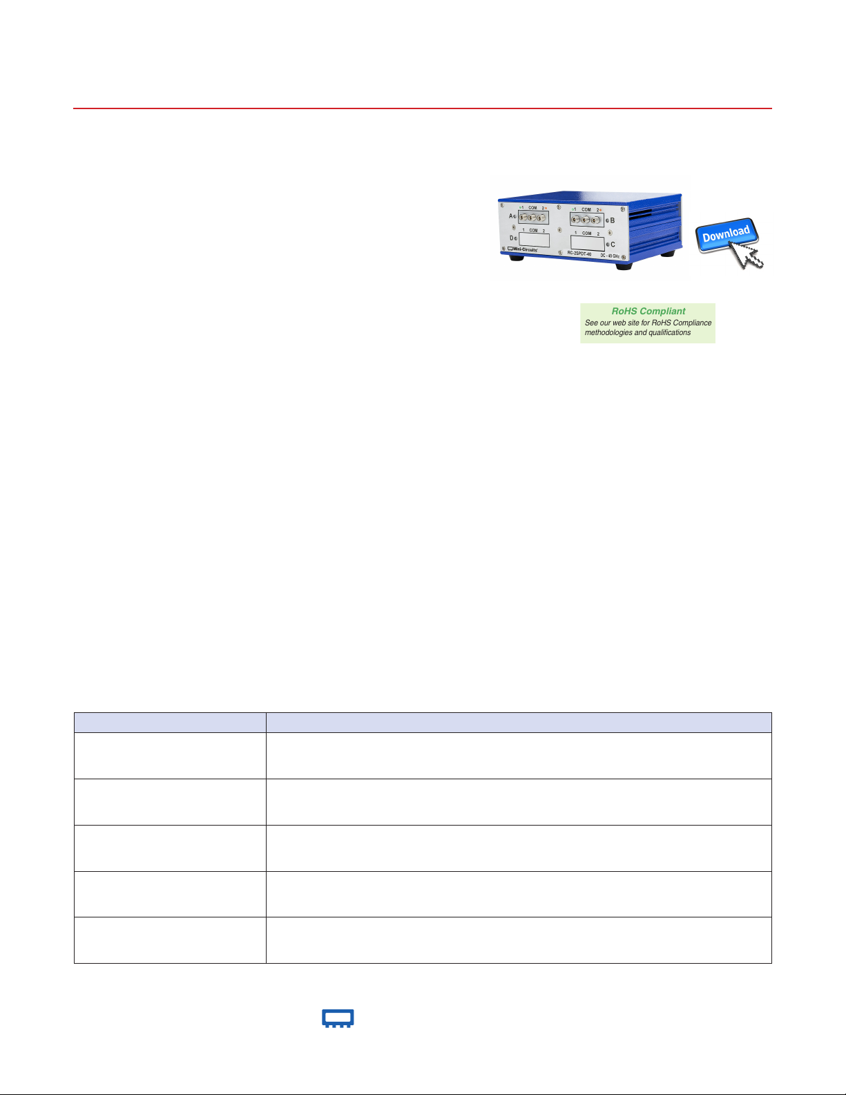
USB & Ethernet Controlled
RF SPDT Switch Matrix
RC-2SPDT-40
50Ω DC to 40 GHz
The Big Deal
• Dual independent mechanical SPDT switches
• Excellent performance to 40 GHz
• High reliability, 2 million switch cycles
• 5W power rating (cold switching)
Case Style: LM3149
Software Package
Typical Applications
• 5G node / device testing
• Automated test equipment
• Fail-safe / redundancy switching
Product Overview
Mini-Circuits’ RC-2SPDT-40 comprises of two independently controlled, electro-mechanical SPDT switches. Each switch
operates over an extremely wide bandwidth, from DC to 40 GHz with high isolation and low insertion loss. The reective switches
are of a failsafe and break-before-make-conguration, with a minimum lifetime of 2 million switching cycles per switch when
used within the noted specications.
The switch box is constructed in a compact, rugged metal case (4.5 x 6.0 x 2.25”) with all 2.92mm (f) RF connectors on the
front panel. The switches are controlled via USB or Ethernet, allowing control directly from a PC, or remotely over a network.
Full software support is provided, including our user-friendly GUI application for Windows and a full API with programming
instructions for Windows and Linux environments (both 32-bit and 64-bit systems).
Key Features
Feature Advantages
Two mechanical SPDT switches Mechanical reective switches provide highly reliable and repeatable performance.
Operation from DC to 40 GHz
Break-before-make conguration
USB & Ethernet control
Full software support
Supports a wide range of RF test and signal routing applications, including 2G, 3G, 4G and 5G, with
a single device
Prevents a momentary connection of the old and new signal paths, reducing the inconsistent transient
effects that could otherwise be observed during switching
USB HID and Ethernet (HTTP / Telnet) interfaces provide easy compatibility with a wide range of
software setups and programming environments
User friendly Windows GUI (graphical user interface) allows manual control straight out of the box,
while the comprehensive API (application programming interface) with examples and instructions
allows easy automation in most programming environments
®
www.minicircuits.com P.O. Box 350166, Brooklyn, NY 11235-0003 (718) 934-4500 sales@minicircuits.com
Rev. A
ECO-005746
RC-2SPDT-40
MCL NY
210305
Page 1 of 7
Page 2
Mini-Circuits
RF SPDT Switch Matrix
State 1
IN
State 2
RC-2SPDT-40
Electrical Specications at 25°C
Parameter Conditions (GHz) Min. Typ. Max. Units
Frequency Range DC 40 GHz
DC - 12 — 0.2 0.5
Insertion Loss
26 - 40 — 0.6 1.1
DC - 12 60 80 —
Isolation
26 - 40 50 65 —
DC - 12 — 1.25 —
VSWR
26 - 40 — 1.50 —
Switching Time — — 25 — ms
DC - 12 — — 20
RF Input Power (Cold Switching)
26 - 40 — — 5
Switch Lifetime (per switch)
Rated Voltage (24V DC Input)
Rated Current (USB) — 10 20 mA
1
Hot switching power above this level will degrade the switch lifetime.
100mW hot switching
1W hot switching — 1 —
All switches in state 2 — 440 —
All switches in state 1 — 90 —
1
2 — —
million cycles
dB12 - 26 — 0.3 0.7
dB12 - 26 55 75 —
:112 - 26 — 1.30 —
W12 - 26 — — 10
mA
Absolute Maximum Ratings
Operating Temperature 0°C to 40°C
Storage Temperature -15°C to 85°C
Supply Voltage 26V
Switching Conguration (Per Switch):
• Fail-safe
• Reective
J1
J2
J1
J2
Connections
Port Name Connector Type
RF Switch A (Com, 1 & 2) 2.92mm female
RF Switch B (Com, 1 & 2) 2.92mm female
USB USB type-B
Ethernet / LAN RJ45
24V DC Input 2.1mm center positive DC socket
®
www.minicircuits.com P.O. Box 350166, Brooklyn, NY 11235-0003 (718) 934-4500 sales@minicircuits.com
Page 2 of 7
Page 3
Mini-Circuits
RF SPDT Switch Matrix
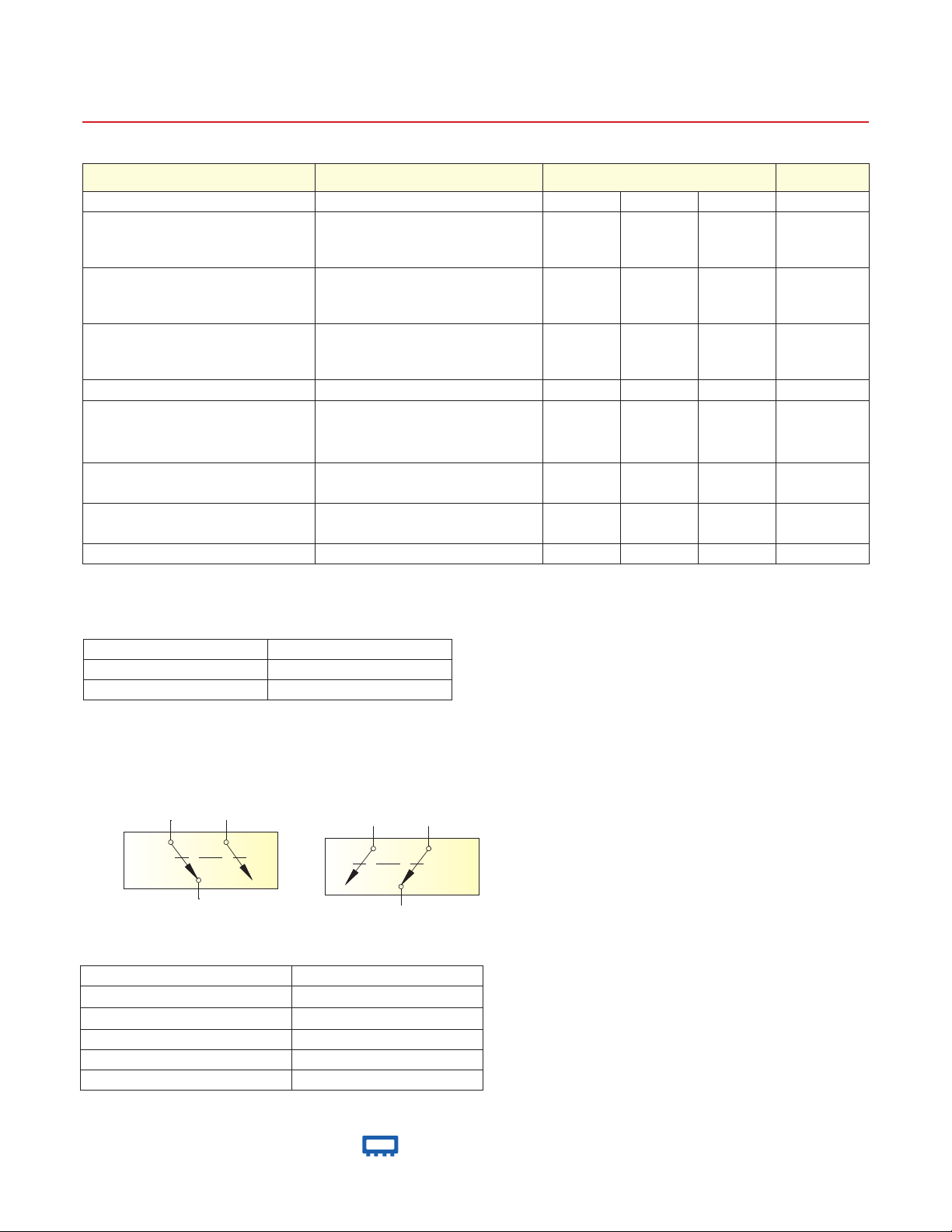
0
20
40
60
80
100
120
140
0 10000 20000 30000 40000
Isolation (dB)
Frequency (MHz)
Isolation
IN - J1 (when IN - J2)
IN - J2 (when IN - J1)
0.00
0.05
0.10
0.15
0.20
0.25
0.30
0.35
0.40
0.45
0.50
0 10000 20000 30000 40000
Insertinon Loss (dB)
Frequency (MHz)
Insertion Loss
IN - J1 IN - J2
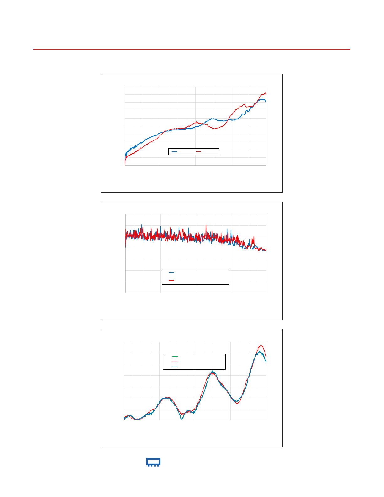
1.00
1.05
1.10
1.15
1.20
1.25
1.30
1.35
0 10000 20000 30000 40000
VSWR
Frequency (MHz)
VSWR
IN
J1 (when IN - J1)
J2 (when IN - J2)
Typical Performance Data
RC-2SPDT-40
www.minicircuits.com P.O. Box 350166, Brooklyn, NY 11235-0003 (718) 934-4500 sales@minicircuits.com
®
Page 3 of 7
Page 4

Mini-Circuits
RF SPDT Switch Matrix
A B C D E F G H J K L M N P R S wt
Outline Drawing (LM3149)
A
RC-2SPDT-40
S
R
B
TOP VIEW
E
F
FRONT VIEW
G
N
P
REAR VIEW
FROM THE BOTTOM OF
L
M
BOTTOM VIEW
Outline Dimensions ( )
6.00 4.50 2.25 .36 .99 1.52 .99 .52 .43 .28 .375 6.75 3.500 .26 .32 .44 grms
152.4 114.3 57.2 9.14 25.1 38.6 25.1 13.21 10.92 7.11 9.5 171.5 88.9 6.6 8.1 11.2 880
inch
mm
®
www.minicircuits.com P.O. Box 350166, Brooklyn, NY 11235-0003 (718) 934-4500 sales@minicircuits.com
WITH THE FASTENERS
BORE HOLES IN THE
Page 4 of 7
Page 5

Mini-Circuits
RF SPDT Switch Matrix
RC-2SPDT-40
Software Specications
Software & Documentation Download:
• Mini-Circuits’ full software and support package including user guide, Windows GUI, DLL les, programming manual and
examples can be downloaded free of charge from https://www.minicircuits.com/softwaredownload/rfswitchcontroller.html
• Please contact testsolutions@minicircuits.com for support
Minimum System Requirements:
Parameter Requirements
Interface USB HID & Ethernet (HTTP & Telnet)
GUI Windows 98 or later
System
Requirements
Hardware Pentium II or later with 256 MB RAM
USB API DLL Windows 98 or later and programming environment with ActiveX or .NET support
USB Direct Programming Linux, Windows 98 or later
Ethernet
Windows, Linux or Mac computer with a network port and Ethernet TCP/IP support
Application Programming Interface (API)
Ethernet Support:
• Simple ASCII / SCPI command set for attenuator control
• Communication via HTTP or Telnet
• Supported by most common programming environments
USB Support (Windows):
• ActiveX COM DLL le for creation of 32-bit programs
• .NET library DLL le for creation of 32 / 64-bit programs
• Supported by most common programming environments (refer to application note AN-49-001 for summary
of supported environments)
USB Support (Linux):
• Direct USB programming using a series of USB interrupt codes
Full programming instructions and examples available for a wide range of programming environments / languages.
®
www.minicircuits.com P.O. Box 350166, Brooklyn, NY 11235-0003 (718) 934-4500 sales@minicircuits.com
Page 5 of 7
Page 6

Mini-Circuits
RF SPDT Switch Matrix
Graphical User Interface (GUI) for Windows - Key Features
• Connect via USB or Ethernet
• Run GUI in “demo mode” to evaluate software without a hardware connection
• View and set switch states at the click of a button
• Congure and run timed switching sequences
• Set start-up switch state
• Congure Ethernet IP Settings
RC-2SPDT-40
®
www.minicircuits.com P.O. Box 350166, Brooklyn, NY 11235-0003 (718) 934-4500 sales@minicircuits.com
Page 6 of 7
Page 7

Mini-Circuits
RF SPDT Switch Matrix
Ordering Information
Refer to Mini-Circuits’ website for pricing and availability information:
https://www.minicircuits.com/WebStore/dashboard.html?model=RC-2SPDT-40
Model Description
RC-2SPDT-40
Included Accessories Part No. Description
USB
& Ethernet controlled 2 x SPDTswitch matrix
AC/DC-24-3W1
AC/DC 24VDC Grounded Power Adaptor.
Operating temperature: 0°C to +40°C, I
Max
RC-2SPDT-40
=2.5A
CBL-3W1-XX
USB-CBL-AB-3+
AC Power Cords
5.
If you need a Power cord for a country not listed please contact testsolutions@minicircuits.com
5
Part No. Description
CBL-3W1-US Power Cord for United States
CBL-3W1-EU Power Cord for Europe
CBL-3W1-UK Power Cord for United Kingdom
CBL-3W1-AU Power Cord for Australia and China
CBL-3W1-IL Power Cord for Israel
AC Power Cord (Select one power cord from below with
each Switch Matrix box)
2.7 ft (0.8 m) USB Cable: USB type A(Male) to USB
type B(Male)
Optional Accessories Description
USB-CBL-AB-3+ 2.7 ft (0.8 m) USB Cable: USB type A(Male) to USB type B(Male)
USB-CBL-AB-7+ 6.8 ft (2.1 m) USB Cable: USB type A(Male) to USB type B(Male)
USB-CBL-AB-11+ 11 ft (3.4 m) USB Cable: USB type A(Male) to USB type B(Male)
CBL-RJ45-MM-5+ 5 ft (1.5 m) Ethernet cable: RJ45(Male) to RJ45(Male) Cat 5E cable
BKT-272-08+
Bracket (One set of 2 each)
Additional Notes
A. Performance and quality attributes and conditions not expressly stated in this specication document are intended to be excluded and do not form a part of this
specication document.
B. Electrical specications and performance data contained in this specication document are based on Mini-Circuit’s applicable established test performance criteria and
measurement instructions.
C. The parts covered by this specication document are subject to Mini-Circuits standard limited warranty and terms and conditions (collectively, “Standard Terms”);
Purchasers of this part are entitled to the rights and benets contained therein. For a full statement of the Standard Terms and the exclusive rights and remedies
thereunder, please visit Mini-Circuits’ website at www.minicircuits.com/MCLStore/terms.jsp
®
www.minicircuits.com P.O. Box 350166, Brooklyn, NY 11235-0003 (718) 934-4500 sales@minicircuits.com
Page 7 of 7
 Loading...