

Mini-Circuit RC-3MTS-40 User manual
Mini-Circuits
USB & Ethernet Controlled
RoHS Compliant
See our web site for RoHS Compliance
methodologies and qualifications
RF Transfer Switch Matrix
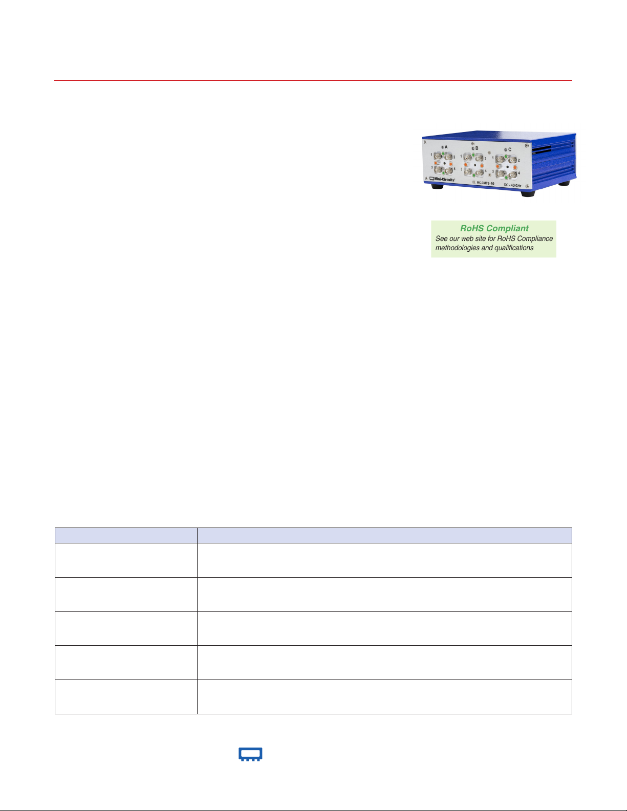
RC-3MTS-40
50Ω DC to 40 GHz
The Big Deal
• Three mechanical transfer switches
• Wideband performance up to 40 GHz
• High reliability, 2 million switch cycles
• High isolation
Case Style: SH3143
Typical Applications
• 5G node / device testing
• Automated test equipment
• Fail-safe / redundancy switching
• Switch matrices
Product Overview
Mini-Circuits’ RC-3MTS-40 comprises of three independently controlled, electro-mechanical transfer switches. Each switch
operates over a wide bandwidth, from DC to 40 GHz with high isolation (70 dB typical), low insertion loss (0.5 dB typical) and high
input power rating. The switches are of a fail safe and break-before-make-configuration using a patented design which ensures
long-term reliability, with a minimum life time of 2 million switching cycles when used within the noted specifications.
The switch box is constructed in a compact, rugged metal case (4.5 x 6.0 x 2.25”) with all 2.92mm(f) RF connectors on the
front panel.The switches are controlled via USB or Ethernet, allowing control directly from a PC, or remotely over a network.
Full software support is provided, including our user-friendly GUI application for Windows and a full API with programming
instructions for Windows and Linux environments (both 32-bit and 64-bit systems).
Key Features
Feature Advantages
Three transfer switches
Fail-safe design
Break-before-make configuration
USB & Ethernet control
Full software support
Transfer switches provide a simple DPDT switch application (2 input to 2 output switch matrix) and are
a useful building block in much larger switch matrices
The switches revert to a known default state when the DC supply is removed, allowing their use in
systems that must continue to operate safely in the event of power failure
Prevents a momentary connection of the old and new signal paths, reducing the inconsistent transient
effects that could otherwise be observed during switching
USB HID and Ethernet (HTTP / Telnet) interfaces provide easy compatibility with a wide range of
software setups and programming environments
User friendly Windows GUI (graphical user interface) allows manual control straight out of the box,
while the comprehensive API (application programming interface) with examples and instructions
allows easy automation in most programming environments
®
www.minicircuits.com P.O. Box 350166, Brooklyn, NY 11235-0003 (718) 934-4500 sales@minicircuits.com
REV. A
ECO-005910
RC-3MTS-40
MCL NY
210203
Page 1 of 7
Mini-Circuits
USB & Ethernet Controlled
RF Transfer Switch Matrix
Electrical Specications at 25°C
Parameter Conditions
Frequency Range DC 40 GHz
DC - 12 GHz — 0.15 0.40
Insertion Loss
26 - 40 GHz — 0.50 0.80
DC - 12 GHz 60 90 —
Isolation
26 - 40 GHz 50 70 —
DC - 12 GHz
VSWR
26 - 40 GHz
Switching Time — — 25 — ms
RF Input Power
(Cold Switching)
Switch Lifetime (per Switch)
Rated Voltage
Rated Current (24V DC Input)
Rated Current (USB) — 10 20 mA
1
Maximum power per path, with all portS terminated into 50Ω
2
Hot switching power above this level will degrade the switch lifetime.
1
DC - 12 GHz 20
12 - 26 GHz 10 W
26 - 40 GHz 5
<0.1W hot switching
0.1 - 1W hot switching — 1 —
24VDC input 23 24 25
USB port — 5 —
Both switches in state 2 — 530 840
Both switches in state 1 — 90 120
2
Min. Typ. Max. Units
— 1.05
— 1.50
2 — —
RC-3MTS-40
million cycles
dB12 - 26 GHz — 0.25 0.70
dB12 - 26 GHz 55 85 —
:112 - 26 GHz — 1.20
V
mA
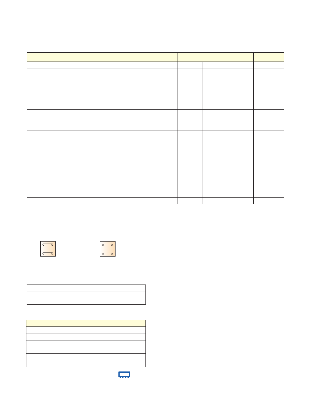
Switching States (per Switch)
J1
J3
State 1
J2
J4
J1
J3
State 2
J2
J4
Absolute Maximum Ratings
Operating Temperature 0°C to 40°C
Storage Temperature -15°C to 85°C
Supply Voltage 26V
Connections
Port Name Connector Type
RF Switch A (J1, J2, J3 & J4) 2.92mm female
RF Switch B (J1, J2, J3 & J4) 2.92mm female
RF Switch C (J1, J2, J3 & J4) 2.92mm female
USB USB type-B
Ethernet / LAN RJ45
24V DC Input 2.1mm center positive DC socket
www.minicircuits.com P.O. Box 350166, Brooklyn, NY 11235-0003 (718) 934-4500 sales@minicircuits.com
®
Page 2 of 7
Mini-Circuits
USB & Ethernet Controlled
RF Transfer Switch Matrix
RC-3MTS-40
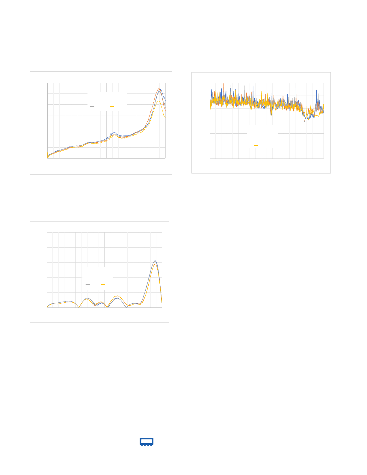
Insertion Loss
0.7
0.6
0.5
0.4
dB
0.3
0.2
0.1
0
0 10000 20000 30000 40000
J1 - J2 J1 - J3
J2 - J4 J3 - J4
Frequency (MHz)
VSWR
2
1.9
1.8
1.7
1.6
1.5
:1
1.4
1.3
1.2
1.1
1
0 10000 20000 30000 40000
J1 J2
J3 J4
Frequency (MHz)
120
Isolation
100
80
60
dB
40
20
0
0 10000 20000 30000 40000
J1 - J2
J1 - J3
J2 - J4
J3 - J4
Frequency (MHz)
®
www.minicircuits.com P.O. Box 350166, Brooklyn, NY 11235-0003 (718) 934-4500 sales@minicircuits.com
Page 3 of 7
 Loading...