

Page 1
http://mini-box.com, Cool Embedded PCs
7) Connect the LED wire to the LED output of your M1-ATX / M2-ATX (consult PSU
manual) for LED pins.
VoomPC™ Automotive PC Enclosure
Mini-ITX Car PC Enclosure
8) Connect the ON/OFF wire harness (provided in the PSU package) to the M1-ATX
ON/OFF controller and to the ON/OFF motherboard switch. (consult your PSU manual).
9) (Optional) Connect the Amp enable wire harness to your Amp. Please pay special
attention to the polarity of the wires. NOTE: Your Amplifier remote control unit actually
needs only one wire (RMT), GND is optional.
10) Hook up Monitor, Keyboard, etc and test your system by turning ignition ON.
11) Secure the VoomPC using the 4 front/back mounting screws. If you don’t want to drill
holes into your car chassis, stick large Velcro pads to the bottom plate of the VoomPC
(the hook side) and attach to your car’s carpet – a strong adhesion will be formed.
Installation Guide
Version 1.1
P/N VOOM-01
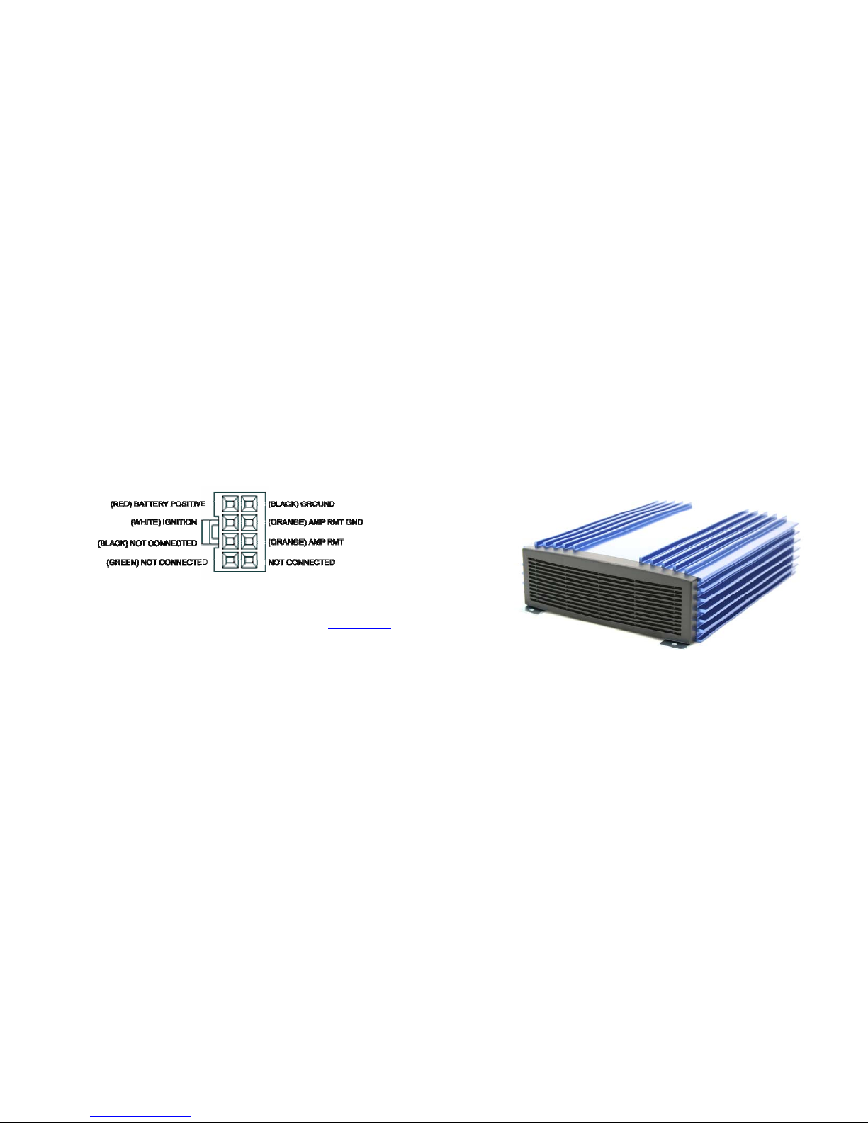
4.0 Power Connector Wiring Diagram
(NOTE: Versions sold after 01/01/2006 will have the AMP RMT GND wire black)
Figure 1.3, power connector diagram
Connector type is Molex “mini-fit JR” series, 2 x 4 configuration. Consult
www.molex.com
for additional information on housings and mating pins (male/female). All “mini-fit JR”
parts can be purchased on-line from www.digi-key.com.
NOTE: The Black and Green wire harness labeled “not connected” is intended to special
projects use. For example , should you need additional 5V or 12V output, you could take
advantage of this pre-installed wires.
Before you start…
6.0 Mechanical
-Dimensions:
210(W)x254(L)x56(H)mm
Please take a moment and read this manual before you install the VoomPC™ in your
vehicle. Often times, rushing into unit installation can result in serious damage
to your motherboard, power supply and probably your car’s electrical system.
The VoomPC has a wire harness that need to be connected to the car’s electrical
system. During installation, always double check the polarity of your wires with a
voltmeter.
-Weight, including packaging: 2.85Kg
5.0 Support and warranty
Standard Hardware Warranty 1Year / US, 2 Year EU
Installation support: 30days via email, support@mini-box.com.
Additional accessories can be purchased on-line from www.mini-box.com.
VoomPC Installation Guide Page 4
Page 2

http://mini-box.com, Cool Embedded PCs
VoomPC Installation Guide Page 3
http://mini-box.com, Cool Embedded PCs
1.0 Introduction
3.0 VoomPC installation steps
Thank you for purchasing the VoomPC mini-ITX vehicle enclosure.
1) Install the motherboard on the base plate using four screws. (See figure 1.0)
The VoomPC was designed to work with a wide variety of main boards such as the VIA
mini-ITX boards as well as low power Pentium-M OR Celeron-M. Please note that
powering full power P4 or AMD systems is not recommended due to excessive heat
dissipation. If using processors with TPD of 40 watts or more, please use two 40mm fans
for increased air circulation.
2) Install the 2.5” hard drive (see area B). Place the 4 silicone rubber shock absorbent
pads over the hard drive mounting holes. Fasten the hard drive using 4 undercut M3
screws attached from the bottom. (See figure 1.1)
2.0 Required tools
In order to install the VoomPC in your vehicle you will need the following tools / materials:
-Phillips screwdriver and Wire cutter / stripper
-Few feet of wire (AWG 12-16), preferably color coded, used for power.
-Voltmeter (optional).
3) Attach a 44-40 pin IDE cable to the hard drive and motherboard.
4) Attach the M1-ATX or M2 ATX power supply over the hard drive, using the remaining
standoffs. (See figure 1.0)
5) Connect the ATX cable harness provided with your power supply to the motherboard.
Use small tie-wraps to manage the ATX cable harness in order to improve the air flow.
NOTE: If you are using the EPIA MII 10000 or EPIA MII 12000, please look for the ATX
power extender bus, a custom PCB that eliminates the ATX cable harness, available
http://www.mini-box.com
6) Connect the Red / Black / White (terminated in fastons connectors) to the power
supply. Red is un-switched battery, white is switched battery (ignition) and Black is GND.
TIP: Usually the switched battery (ignition) is present on your cigarette lighter or most of
your 12V power wires. Un-switched battery, harder to find, is present on your alarm
system or other ‘always on’ electronics. Use a volt-meter to detect switched vs unswitched wires. If hard to find, connect directly to the battery. Make sure you have firm
and sturdy contacts to the car’s power system.
NOTE: If you purchased the M1-ATX separately, you will not need the extra Faston wire
assemblies provided with the unit.
Figure 1.0, bottom mounting plate
VoomPC Installation Guide Page 2
 Loading...