

Page 1
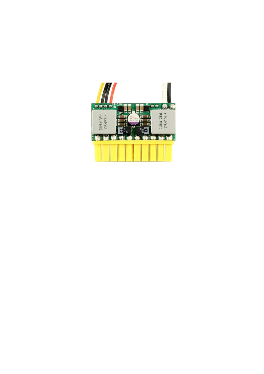
picoPSU-80
12V, 80Watt ATX Power Supply
Quick Installation Guide
Version 1.0d
Introduction
Based on an improved electrical design of the picoPSU-90, the
picoPSU-80 is a small yet powerful and fully compliant ATX power
supply designed to power a wide variety of low power motherboard
from a single 12V regulated power source. picoPSU-80 has been
optimized for the latest generation of power efficient Atom
processors resulting in the highest efficiency at light loads while
capable of peak power requirements to an impressive array of
peripherals.
The PICOPSU-80 is the only snap power supply solution for
general purpose motherboards. Compatible with an entire range of
mini-ITX motherboards the picoPSU-80 provides cool, silent power
for system. The PICOPSU-80 has many advantages over a regular
power supply:
P/N picoPSU-80
Page 2
Mini-Box.com ATX DC-DC Converter Series
-Smallest ATX PSU to date
-100% silent operation
-Low heat dissipation with efficiency over 96%
-Plugs directly into the motherboard’s power connector, no cable
mess
Quick installation Instructions
The PICOPSU-80 has been specifically designed for the Mini-ITX
form factor, thus eliminating the need for ATX power cables. It is
also 1U compliant – height will not exceed 1U form factor.
1) After the picoPSU module was ‘snapped in’, hook the hard drive
power or floppy power to your floppy/hard drives. If more hard
drives or floppy connectors are needed, use a HDD/floppy “Y”
splitter cable.
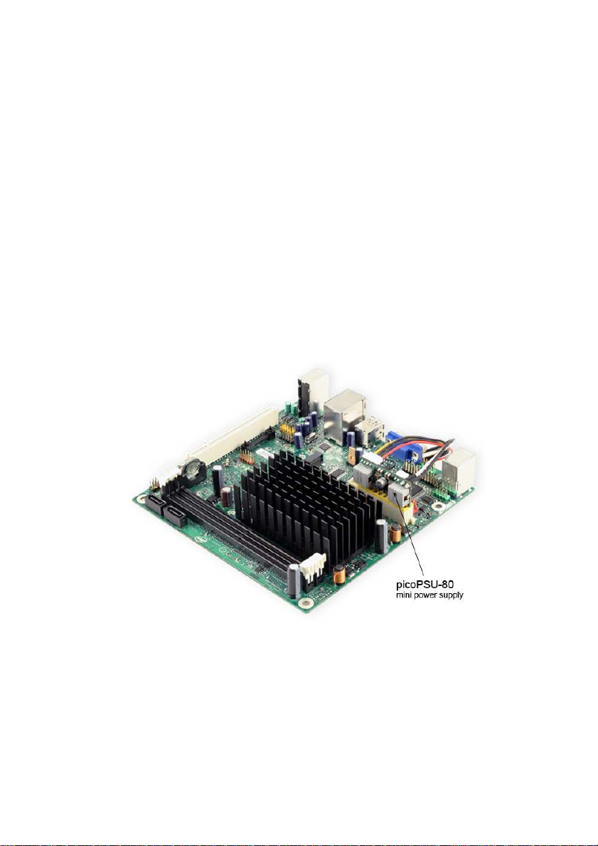
PicoPSU-80 shown with the D510MO Intel Motherboard.
2) Connect a 12 VDC power adapter (or any 12V source) to the
DC-to-DC connector, center pin / white wire is positive (+).
picoPSU-80 Quick Installation Guide Page 2
Page 3

Mini-Box.com ATX DC-DC Converter Series
3) Turn on the PC using the motherboard ON/OFF motherboard
switch
Typical configuration
The picoPSU-80 has been tested with all mini-ITX board (VIA C3,
VIA C7, low power AMD and Intel Atom) under virtually any disk /
floppy / CDROM configurations. Additionally, the PICOPSU-80 can
power low boards equipped with an 12VATX 4 pin connector
(additional cable required). NOTE: The hard drive cable harness
can be disconnected in case the user does not need any
peripheral. Additionally, the cable harness can be made to any
length or output connector type provided that the max load does not
exceed 3A for GND return. Please look under specifications for the
mating connector type.
Removing the picoPSU-80
In order to remove the picoPSU you must release the power
connector latch and then remove the unit. Gently lift the picoPSU
out from the ATX connector, by grabbing from the picoPSU PCB,
not from components or the wire harness.
Specifications, picoPSU-80, 80Watts DC-DC ATX Power Supply
Power Ratings
Volts (V) Max Load (A) Peak Load (A) Regulation %
5V 6A* 7A +/- 1.5%
5VSB 1.5A 2A +/- 1.5%
3.3V 5A* 7A +/- 1.5%
-12V 0.05A 0.1A +/- 5%
12V 4A 7A Switched input
*At max load, forced air ventilation is required. For fanless or improper ventilation operation derate the output of the 3.3 and 5V rails until PSU temperature falls below 65C. Peak load should
not exceed 60 seconds. Combined max power output should not exceed more than 95watts.
Efficiency Ratings, 3.3 and 5V rail
CH1=5V Efficiency (%) CH2=3.3V Efficiency (%)
1A 94% 1A 93%
2A 96% 2A 96%
5A 94% 5A 92%
7A 86% 7A 86%
Input Requirements: 12V regulated, min=1A, max=10A (load
dependent). Over-voltage shutdown will occur at ~13-13.5V.
picoPSU-80 Quick Installation Guide Page 3
Page 4

Mini-Box.com ATX DC-DC Converter Series
Size: 44.5mm(L) * 20mm(W) * 30mm (H) (1U compliant)
Weight: 45gramms, including cable harness, 20 grams without
cable harness.
DC-Jack: Female, panel mount, 2.5*5.5*10 mm.
Connectors
Molex 39-01-2200 compatible, two 3.5” drive power connectors
(PATA and SATA) and one optional P4-12V 4 connector (mini-fit JR
4p). Header and mating connector for the removable cable
harness can be found at:
http://www.jst-mfg.com/product/pdf/eEH.pdf
Overload protection
Over load protection will be effected when either of the loads (+5V
& +3.3V) exceeds > 150% Max Load.
Turn-on Delay
After turning on, at least 20 ms will be needed for the rise of +5VSB
output voltage (measured from 10% to 95%) to reach its peak.
Remote ON/OFF control (PS_ON)
Logic level is LOW - Output voltage is enabled (PS_ON pin)
Logic level is HIGH - Output voltage is disabled (PS_ON pin)
PWR_GD
Logic level is low: PWR_GD=OK
Logic level is high: PWR_GD=not OK (10.5V<V(in)>13.5V or other
fault conditions)
Operating environment: Temperature: -20 to 65 degree
centigrade.
NOTE: Thermal shutdown occurs at 105-115C.
Relative Humidity: 10 to 90 percent, non-condensing.
Efficiency, MTBF: MTBF >60K hours at PSU(temp) < 65 Celsius
Shipping and storage: Temperature -40 to +65 degree
centigrade. Relative humidity 5 to 95 percent, non-condensing
Warranty
1 Year Limited Warranty statement. Warranty is void if
maintenance or calibration is performed by end-user or by use in
conjunction with power modules not provided by mini-box.com.
Support: Email:
Web Site: http://www.mini-box.com
support@mini-box.com
picoPSU-80 Quick Installation Guide Page 4
 Loading...