

Page 1

OPENUPS
6-30V Intelligent Uninterruptible Power Supply
Installation Guide
Version 1.0f
P/N OPENUPS-06
Before you start…
Please take a moment and read this manual before you install the OPENUPS.
Often times, rushing into installing the unit can result in serious damage to your OPENUPS
board, computer. Always double check the polarity of your wires with a voltmeter.
Introduction
Thank you for purchasing the OPENUPS Uninterruptible power supply.
The OPENUPS was designed to provide user specified regulated power output from a wide
input voltage, battery backup, multi-chemistry charging and cell balancing in a single PCBA.
OpenUPS features include:
-USB interface, works with Windows devices (Linux API planned)
-SMBUS slave and I2C master
-Input between 6-30V
-Programmable voltage thresholds,
-Generate any output voltage between 6-24V,
-Supports multiple battery chemistry
-Balances up to 6 series batteries.
-Charge voltage between 6-30V, charge current up to 3A, battery balancing up to 6 cells,
-Coulomb counting (fuel gauge)
-Motherboard ON/OFF pulse control*
Page 2
-Windows detects device as “Battery”, no special drivers required **
*MotherBoard ON/OFF control: The device is able to send ON/OFF 'pulse signals' to
motherboard based on coulomb counter and/or battery voltage level, or based on input voltage
level or when starting.
**Windows “no driver support”: Installs itself as a battery in Windows, using the Windows hid
driver without any driver installation, visible as an icon in tray bar.
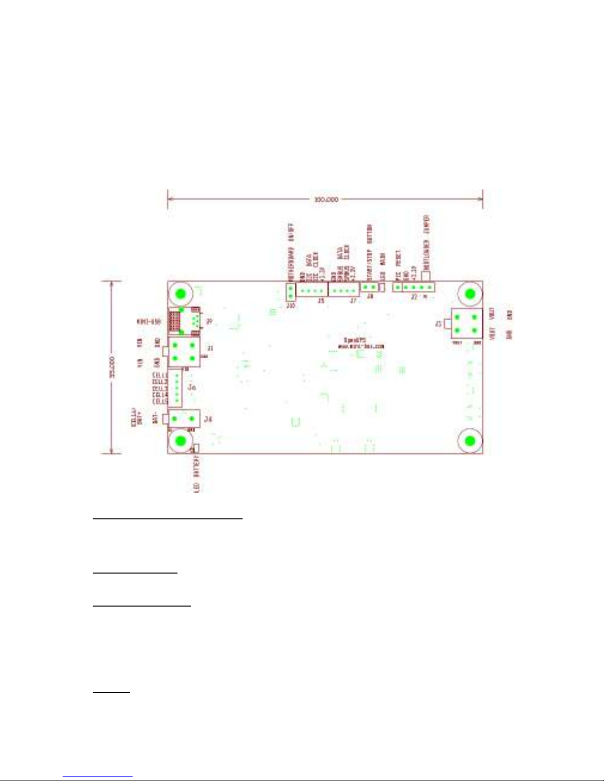
OPENUPS Connection diagram
Power Input/Output Connectors:
J1: Input voltage, (4pin mini-FIT JR)
J4: Battery positive (+) and Battery negative (-) (2 pin mini-FIT JR)
J3: Output voltage (4 pin mini-FIT JR)
Balancing header:
j6: cells 1 to 5, cell6 already connected to Battery (+) (JST PH connector, 5pin)
Interface connectors:
J9: Mini-USB connector (mini-USB)
J10: Motherboard ON/OFF control (0.1” header)
J5: I2C master
(JST PH connector, 4pin)
J7: SMBUS slave (JST PH connector, 4pin)
J8: START/STOP button (0.1” header)
J2: Programming header, bootloader jumper, MCU reset (0.1” pitch)
Display:
Main LED (see status Main LED below)
Battery LED (see Battery LED status below)
Page 3

Bootloader Mode
The device can start in bootloader mode so firmware updates are possible without using the
programming header. Place a jumper between J2.4 and J2.5, than connect the unit to USB to
enter bootloader mode.
Start the HIDBootLoader.exe software provided to flash the new firmware.
Reseting the MCU
Placing shortly a jumper between J2.1 and J2.2 will reset the internal MCU reloading your
reconfigured parameters and restarting the UPS. Care should be taken when using this feature.
Getting Started…
Before you start you would need to connect the unit to USB and configure:
- battery type and capacity (default is PbSO4 and 7000mAh)
- number of cells connected to the balancing headers (default is CELLS=1)
- charge voltages and currents, (default is 14.1V and 1700mA when fast charging)
- output voltage (default is 12V)
- input start/stop voltage thresholds ( default start at 11V, stop at 6V)
- other advanced parameters if needed
NOTE: The device needs to be restarted so the new configuration becomes active.
Simply remove the power and disconnect USB cable to shut down, settings will be
permanently saved.
Warning: Improper configuration (ex: wrong under-voltage, over-voltage, reverse
polarity) can lead to battery damage or your system damage (ex: wrong output value)
Battery Configurations:
This device is a multi chemistry device. Multiple batteries (up to 6 cells, 4.2V max) can
be connected in series (1S, 2S, 3S, 4S, 5S, 6S configuration). Parallel configurations
are also supported but not recommended due to possible decrease in lifespan.
It is possible to connect a battery with more than 4.2V/cell but in this case only 1 cell
should be configured (CELLS=1). Balancing is disabled in this case. This is a typical
example of a 12V SLA battery.
Connect your main battery terminals to the J4 connector. Always double check the
polarity of the connections.
Connect the internal cells to the balancing header J6, if needed. If more than 1 cell and
less than 6 cells are used connect the negative terminal of the battery to the next free
pin on the J6 header.
NOTE: If no balancing wires are connected through the J6 header the CELLS
parameter should be set to 1.
Example: connecting 4 cells( cells 6, 5, 4 and 3)
- The “highest” cell, cell_6, is always connected to the power terminal BAT+ (no need
Page 4

to connect anywhere)
- connect cell_5 to position 5 on J6 header
- connect cell_4 to position 4 on J6 header
- connect cell_3 to position 3 on J6 header
- connect the battery's negative terminal(or GND) to position 2 on J6 header
Starting and Stopping with battery power….
If everything correctly configured pressing shortly the J8 button will turn on the output
and your UPS will be started, energy will be flowing from battery to the output.
Long pressing (5 sec) J8 button will initiate shut down of the UPS. A pulse is sent to
the motherboard than the UPS waits a predetermined UPS_HARDOFF_TOUT (60s by
default) before the output voltage is turned off.
The motherboard's state is sensed by measuring the output power via. If the
motherboard was shut down by the OS no pulse will be sent. The output power
thresholds can be set by setting the POU_LO and POUT_HI parameters. If the
motherboard consumes more than the POUT_HI threshold (meaning motherboard is
not shut down by OS) the pulse will be sent in case shutdown conditions are fulfilled.
Connecting DC input power….
Connect a proper input voltage source to the J1 connector.
If input voltage is present (configurable by thresholds), openUPS will enable the proper
power path and energy will be flowing from input to output and, if necessary, battery
charging is started. Each cell is carefully monitored so that in case of an under-
voltage
or over-voltage event proper actions are taken.
Operating modes:
-Auto restart when Input Power is Present=YES
Output and charging is started once the input power is present.
-Auto restart when Input Power is Present=NO
Only charging is started once the input power is present. The output will be started
once the Start button is pressed.
Main LED blink modes:
1) 5 x (30ms ON,30ms OFF) quick blinks during 750ms period repeatedly: initial
delay
2) 500ms ON , 500ms OFF: UPS is in standby (waiting for proper starting
conditions).
The unit will stay in this state if one of the following conditions does not fulfill:
-Improper battery configuration
-Cell under-voltage and input voltage is not present
3) Steady ON: UPS is running from Input
4) 500msec ON, 2.5 sec OFF: UPS is running on Battery
5) 1 sec ON, 1 sec OFF: OFFDELAY (time between a shutdown condition fulfilled
and the off pulse is sent to the motherboard) set by the
UPS_VBAT_UVP_OFF_TOUT parameter.
Page 5

6) 3x(500ms ON,500ms OFF) + 3 sec OFF repeatedly: Hardware OFF delay (time
between the off pulse is sent and cut off of the output voltage) set by the
UPS_HARDOFF_TOUT, entering deep sleep
Status of Battery LED:
-Fast blinking: incorrect configuration of the cell numbers, or wrong connections on
the balancing header.
-Toggle every 1 sec: Battery is being charged
-Steady ON: Battery is fully charged (100%)
-Steady OFF: (together with main LED's 500msec ON, 2.5 sec OFF:) System is
running on battery
All LEDS OFF:
Unit is in Deep sleep mode consuming very little power. MCU is not powered. Can be
waked up by shorting J8 or if input voltage is present.
Setting Power plans under Windows Operating Systems:
Ex:Vista,Win7
-Right click on the battery icon from the traybar then choose power options from the
context menu. Alternatively you can choose Power Options also from Control Panel
Items.
-Select/create a power plan or modify existing ones.
-In the “Change Advanced power settings” section the critical and low battery levels
and actions can be also modified
Page 6

OPENUPS Characteristics
Minimum Input Operating. voltage 6V
Maximum input Operating voltage 30V
Deep-Discharge shutdown threshold configurable
Input current limit (fuse protected) Mini-blade 10A
Deep Sleep Current Consumption. < 50uA
Storage and operating temperature -40 to +85 degrees Celsius (storage), -40 – 65C (operating)
MTBF 50K Hrs @ 85C, >200K Hrs at 65 (projected)
Efficiency (Input 10-16V) >80-95% (95% max), depending on load V(in) and V(out)
Input connectors Mini-Fit JR
Output Connector Mini-Fit JR
Output/Input Rail Output Current (buck/boost converter):
Maximum input current: 6A*
Peak Input current: 10A (<30 seconds)
Maximum output current: 6A*
Peak output Current: 10A (<30 seconds)
*NOTE: When operating at high voltage (input or output) or/or operating at elevated
temperatures de-rating up to 30% might be necessary, forced ventilation required. For long life
operation, please ensure that hottest component on-board is kept below 65C.
Support and warranty: Standard Hardware Warranty 1Year / US, 2 Year EU.
Page 7

Parameter List:
NAME DESCRIPTION
OPENUPSMODE OPENUPS mode
0- Auto restart when Input Power is
Present=YES
1- Auto restart when Input Power is
Present=NO
UPS_CONFIG Configuration register. Used for enabling
disabling modules. LSB bit is b0.
b6- Stop impulse
b5- Start impulse
b4- Coulomb counter
b3- A/D Low pass Filter module
b2- Balance module
b1- Charge module
b0- Output module
Default is all enabled
UPS_INIT_DELAY_TOUT[s] Initial delay before starting the UPS.
Default is 1 sec.
UPS_VIN_MAX_SHUTDOWN[V] Max allowed input voltage. In case input
voltage exceeds predefined value
shutdown will be initiated.
Default is 35V.
UPS_VIN_MIN_START [V] If input voltage is above this threshold the
UPS will start and take power from the
input.
Default is 11V.
UPS_VIN_MIN_STOP [V] If input voltage is below this threshold the
UPS will try to run on battery.
Default is 6V.
UPS_VCELL_MIN_START [V] If Vin is not present and all the battery
cells are above this threshold the UPS
can start and runs on battery
Default is 11.7V
UPS_VCELL_MIN_STOP [V] If VIN is not present and one of the
battery cells is less than this threshold
during the time period specified by
UPS_VBAT_UVP_OFF_TOUT parameter
the UPS will initiate shut down procedure.
Default is 11.4V
UPS_VBAT_UVP_OFF_TOUT [s] During this period battery cells are
checked against
UPS_VCELL_MIN_STOP. If cell voltage
exceeds UPS_VCELL_MIN_STOP the
timer is rearmed so it can filter unwanted
noise in the system.
Page 8

Default is 5 sec.
UPS_HARDOFF_TOUT[s] After UPS_VBAT_UVP_OFF_TOUT
passed motherboard is signaled to shut
down. The UPS will wait this period so
that the Motherboard can shut down
gracefully, than cut power and enter deep
sleep. This period should not be too long
to prevent battery drain.
Default is 60 sec.
UPS_SWITCHOVER_VBAT_TOUT[ms] After UPS switches to battery, can switch
back to Vin only after this time elapses.
Default is 1000ms.
UPS_SWITCHOVER_VIN_TOUT[ms] After UPS switches to input, can switch
back to battery only after this time
elapses.
Default is 1ms.
DCHG_IMAX[mA] Max allowed discharge current. In case
discharge current exceeds this threshold
shutdown will be initiated.
Default is 10000 mA.
CAPACITY[mAh] Battery Capacity.
Default 7000mAh.
CHG_BAT_TYPE The battery chemistry to be charged.
0- PbSO4 (float charge is applied)
1- LiFePO4 (float charge is not applied)
2-LiPO(float charge is not applied)
Other (float charge is not applied)
Default is 0.
CHG_VCOND[V] Conditioning/Pre-charge voltage. Charge
current is limited to CHG_ICOND until cell
voltage exceeds this value and for at least
CHG_TCOND time .
Default is 11.2V.
CHG_ICOND[mA] Conditioning/Precharge current. Charge
current is limited to this value until cell
voltage exceeds CHG_VCOND value and
for at least CHG_TCOND time .
Default is 100mA.
CHG_TCOND [s]
Conditioning/Precharge time. Charge
current is limited to CHG_ICOND value
until cell voltage exceeds CHG_VCOND
value and it is applied during this time.
Default is 30 sec.
CHG_IBULK[mA] Fast charge current limit (constant current
mode)
Default is 1750mA.
CHG_BULK_STOP_VOLTAGE[V/cell] Maximum allowed bulk charge
Page 9

voltage/cell during constant
current/constant voltage charging
Default is 14.1V
CHG_HYSTERESIS[V/cell] An over-voltage value
(CHG_BULK_STOP_VOLTAGE
+CHG_HYSTERESIS ) that it is allowed
when charging.
If one of the cells exceeds this value
charging is immediately stopped.
Default is 100mV/cell.
CHG_START_VOLTAGE [V/cell] If cell voltage is below this value charging
can be started. For PbSO4 battery this
also sets the floating charge voltage.
Default is 13.5V/cell
CHG_IMIN [mA] If charge current in CV mode is less than
this value
PbSO4: enter maintenance mode and
apply the float charge
voltage(CHG_START_VOLTAGE)
LiFePO4,LiPO: cut off the charge voltage
Default is 290mA
CHG_IFLOAT Charge current limit in float charge mode
for PbSO4 batteries.
Default is 100mA.
CHG_GLOBAL_TOUT Global charge timeout.
Default is 1260 minute.
CHG_TOPPING_TIMER For Lithium based batteries after an
overvoltage condition is detected for a cell
a resting period is set by this timer before
applying a small topping charge in case
other cells are still not charged.
Default is 1800s.
CHG_TEMP_PCB[°C] Charge current is limited by
CHG_ILIMIT_TEMP_PCB amount every
30s,if board temperature exceeds this
value. Can limit the charge current till
CHG_IBULK/4 value.
Defaults is 60°C.
CHG_ILIMIT_TEMP_PCB [A] Limit charge current with this amount if
board temperature exceeds
CHG_TEMP_PCB.
Default is 50mA.
CHG_FREQUENCY[kHz] The working frequency of the charger
buck-boost converter
Default is 333kHz.
CELLS[pcs] Number of configured cells to
charge/balance
Page 10

Default is 1pcs.
BAL_VCELL_MIN[V] Balancing is allowed if cell voltages are
above this value.
Default is 3V
BAL_VCELL_DIFF_START [V] If the voltage difference between cells
exceeds this value start balancing the
cells.
Default is 70mV.
BAL_VCELL_DIFF_STOP[V] If the voltage difference between cells is
less than this value stop balancing the
cells.
Default is 40mV.
OUT_VOLTAGE[V] The output voltage.
Default is 12V.
OUT_FREQUENCY[kHz] The working frequency of the output
buck-boost converter.
Default 300kHz
OUT_MAX_REGULATOR_STEP[nr] Maximum allowed regulation step number
for output module (0-255)
Default 100.
MOB_ONOFF_TOUT[ms] The power switch on the motherboard(if
connected) will be shorted this period to
turn the Motherboard ON or OFF
Default is 500ms
POUT_LO[W] Output power low threshold for
motherboard alive sensing. If output
power is lower than this threshold shut
down impulse will NOT be sent to the
motherboard when shut down conditions
are fullfilled.
Default is 2W.
POUT_HI[W] Output power high threshold for
motherboard alive sensing. If output
power is higher than this threshold shut
down impulse can be sent to the
motherboard when shut down conditions
are fullfilled.
Default is 6W.
OCV_SOC0 Open Circuit Voltage State Of Charge
detection for initial 0% fuel gauge
estimation.
Default is 11.8V
OCV_SOC10 Open Circuit Voltage State Of Charge
detection for initial 10% fuel gauge
estimation.
Default is 11.9V
Page 11

OCV_SOC25 Open Circuit Voltage State Of Charge
detection for initial 25% fuel gauge
estimation.
Default is 12V
OCV_SOC50 Open Circuit Voltage State Of Charge
detection for initial 50% fuel gauge
estimation.
Default is 12.3V
OCV_SOC75 Open Circuit Voltage State Of Charge
detection for initial 75% fuel gauge
estimation.
Default is 12.6V
OCV_SOC100 Open Circuit Voltage State Of Charge
detection for initial 100% fuel gauge
estimation.
Default is 12.8V
WRITE_COUNT[cycle] Number of times the flash memory has
been written. Parameter is Read only.
 Loading...