

mini-box M2-ATX-HV Installation Manual

GND
+
Switch Logic
6-32V DC-
DC
ATX PSU
PC
ATX power
MotherBoard
ON/OFF switch
M2
-
Battery
Ignition
-
SW
+
J8
LED
J5
J6
8bit MCU
Amplifier
Enable
J9
Reverse and
forward protection
Optional On/OFF switch
M2-ATX-HV
6-32V Intelligent Automotive ATX Power Supply
Installation Guide
Version 1.4 (firmware v1.5, 10/15/2009)
P/N M2-ATX-HV-02
Before you start…
Please take a moment and read this manual before you install the M2-ATX-HVHV in your
vehicle. Often times, rushing into installing the unit can result in serious damage
to your M2-ATX-HV-HV board, computer and probably your car’s electrical
system.
The M2-ATX-HV-HV board has several wires that need to be installed in
various places.
When installing, always double check the polarity of your wires with a
voltmeter.
Avoid using the cigarette plug as a power source, often times the contacts are
not capable of delivering high current to your PC.
1.0 Introduction
Thank you for purchasing the M2-ATX-HV-HV power sequencer / vehicle ATX
power supply.
The M2-ATX-HV-HV was designed to work with a wide variety of main boards
such as the VIA C3/C7/nano motherboards as well as AMD, Pentium-M
Celeron or Core2Duo processors.
1.1 M2-ATX-HV-HV Logic Diagram
http://mini-box.com, Cool Embedded PCs
M2-ATX-HV-HV User Guide Page 2
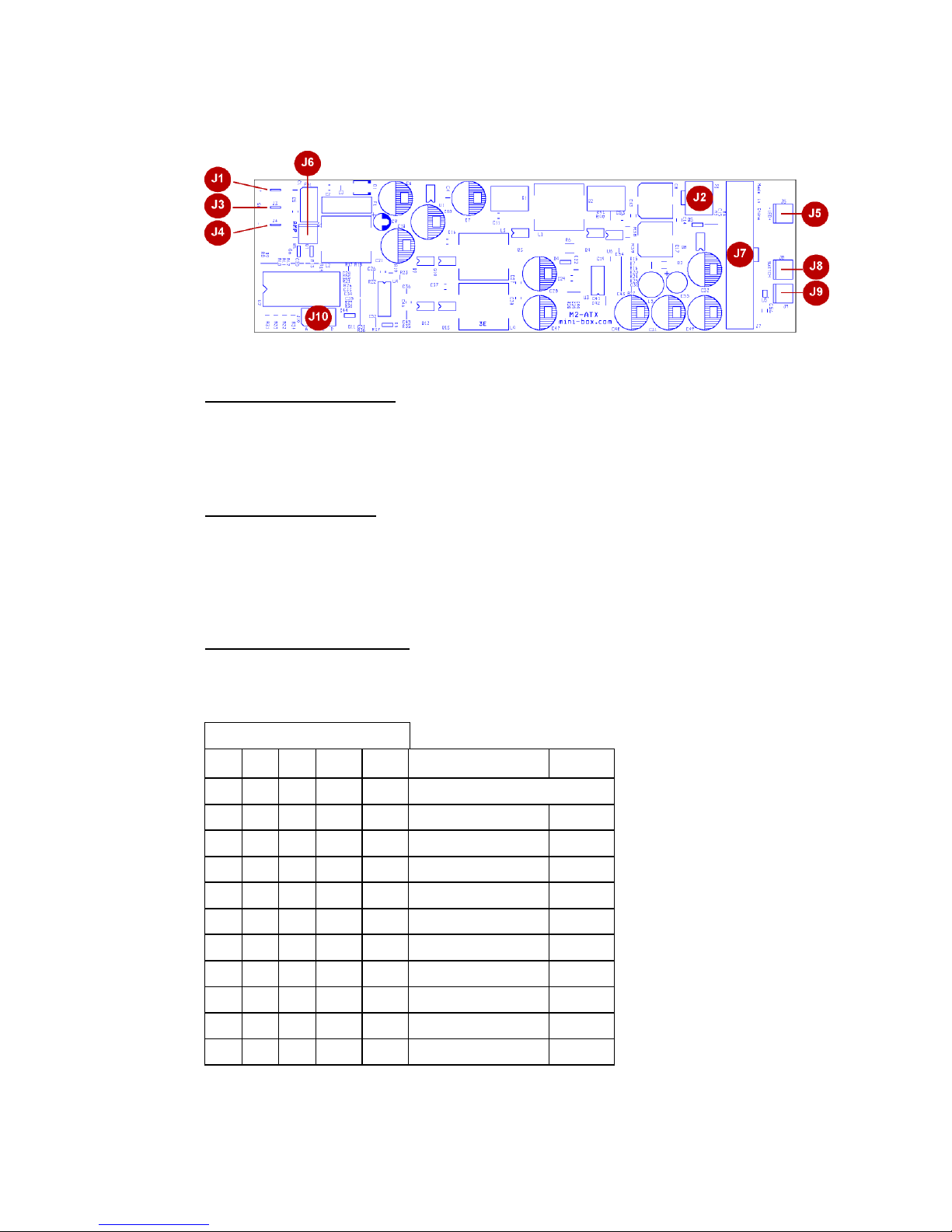
1.2 M2-ATX-HV-HV Connection diagram
M2-ATX-HV-HV, top view
Power Input Connectors
J1 Battery + (un-switched battery, positive)
J3 Ignition (To start connect to Battery +). Do not use in the standard
PSU mode (mode P0).
J4 Battery - (negative)
Controls and Settings
J6 Controls amplifier via remote ON/OFF. Left pin is RMT, Right pin is
GND
J8 To motherboard ON/OFF switch
J10 User jumper settings (A,B,C,D)
J9 To external ON/OFF switch (optional, J8 is in parallel with J9)
Power Output Connectors
J2 Optional P4-12V power
J7 ATX power connector (to motherboard)
J5 To LED (optional)
IMPORTANT:
Always use the
“Hibernate” feature,
never use “Standby”
as it can severely
discharge your
battery over
extended periods of
time.
NEVER use “Hard-
off = NEVER”
settings unless you
understand the risks
of battery depletion.
“Hard-off=NEVER
always keeps 5VSB
rail ON!
*AutoLatch is active during the fist 60s of PC operation (and only during the
first 60 seconds). For example, If Ignition is turned ON and then OFF right
Jumper attached=ON
A B C D
P
Off-delay
(All rails ON)
Hard-off
(5VSB)
OFF OFF OFF OFF
P0
Standard PSU mode
ON OFF OFF OFF
P1
5s + 1min AutoLatch* 1 min
OFF ON OFF OFF
P2
5s+ 1min AutoLatch* 2 hour
ON ON OFF OFF
P3
5s+ 1min AutoLatch* NEVER
OFF OFF ON OFF
P4
30s + 1min AutoLatch* 2 hour
ON OFF ON OFF
P5
30s + 1min AutoLatch* NEVER
OFF ON ON OFF
P6
30min NEVER
ON ON ON OFF
P7
3 hour NEVER
OFF OFF OFF ON
P8
10 min 1 hour
ON OFF OFF ON
P9
15 min 2 hours
OFF ON OFF ON
P10
1 hour 75min
 Loading...