

Page 1

DCDC-USB-200
6-34V high power, I
ntelligent DC-DC converter with USB interface
Quick Installation Guide
Version 1.0c
P/
N DCDC-USB-200
Introduction
The DCDC-USB-200 is a powerful DC-DC power supply designed to power a
wide variety of devices. This DC-DC has a range of intelligent functions not found
in any tradition USB converters. Features include USB interface, programmable
output voltage and scripting as well as automotive modes.
The DCDC-USB-200 device is able to send ON/OFF ‘pulse signals’ to
motherboards based on voltage levels or Ignition sensing, making it an ideal
device for automotive or battery powered installations.
This unit has a wide input range (6-34V) and it can provide a tightly regulated
output ranging from 6 to 24V (default set to 12V). Emissions are reduced using 2
out of sync, spread spectrum buck-boost converters.
Page 2
mini-itx.com ATX DC-DC Converter Series
DCDC-USB-200 Quick Installation Guide Page 2
CONFIG
Timing SchemesOutput voltage
Main mode
Quick installation Instructions
J10
J7
J1J9
J8 J6
D1
VOUT
VIN
DCD-USB-200
Fig 1.0, DCDC-USB-200 layout
J7: Configuration jumpers for Voltage, Mode and Timings.
Left mini-FIT connector: Power input, V(in) – (Red), GND, Ignition *(Yellow)
Right mini-FIT connector: Power output V(out), GND.
J8 : Soft ON/OFF control for motherboard. Connect this to motherboard ON/OFF
pins if you want the motherboard to be controlled by the unit.
J9: mini-USB type B jack. Connect this to a PC to access advanced settings.
J1: USB header for internal connection.
D1 STATE: State LED
J10 : Provides unregulated switched input, to be used in automotive modes to
power various peripherals.
Basic Operation
For basic operation, you would need to connect a power source to V(IN). V(IN) is
on the left side of the board, near the input fuse. Polarity is marked on the PCB
(GND, VIN and Ignition). On the cable harness, GND is black, V(in) is red and
Ignition is white. NOTE: Ignition is not needed for basic operation.
Without any further settings, V(out) will generate 12V regulated. V(out) is located
on the right side of the PCB, near the USB connector. On the cable harness,
Yellow is positive and GND is negative.
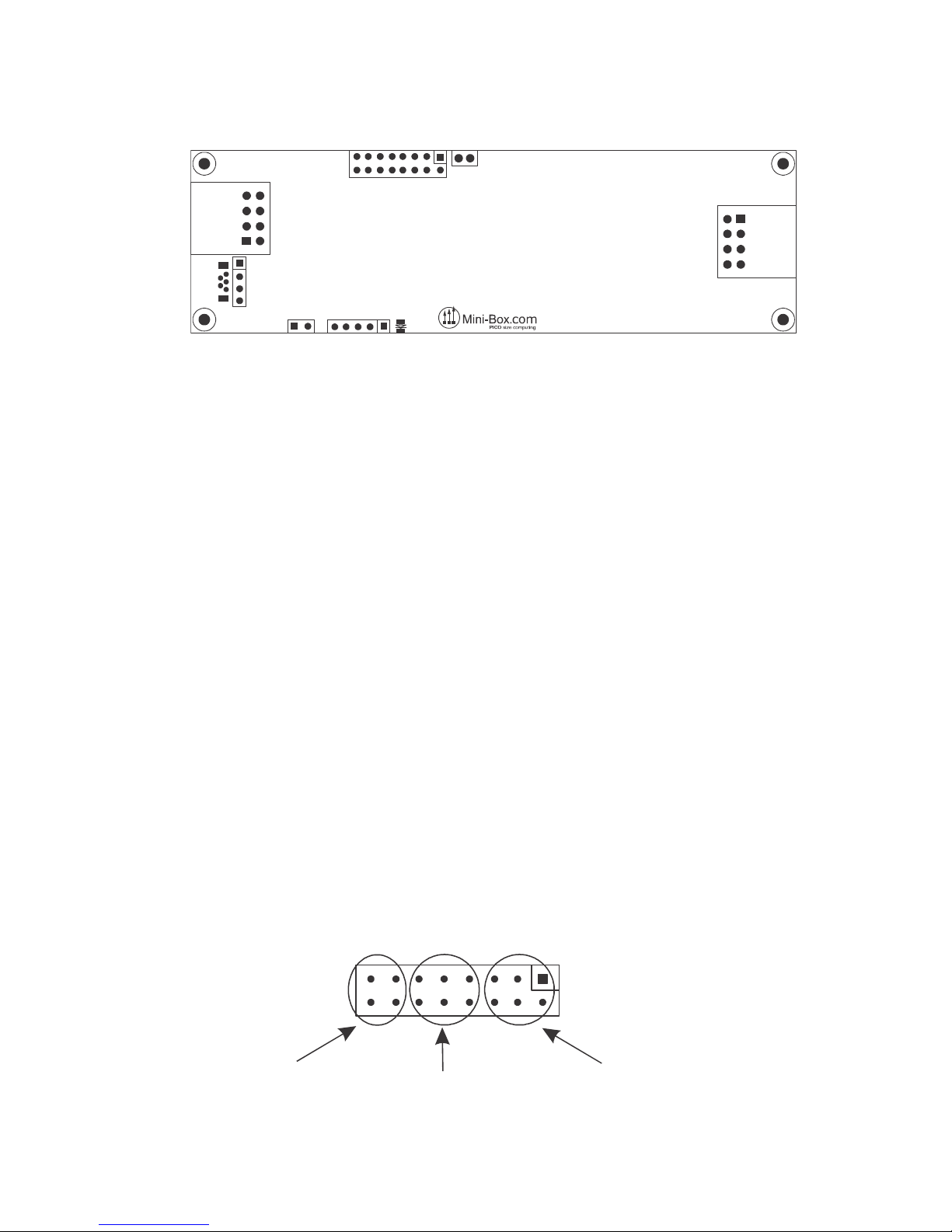
Configuration jumpers
The configuration header J7 (marked CONFIG) is the most important header in
this board. It is divided in 3 sections:
Page 3

mini-itx.com ATX DC-DC Converter Series
DCDC-USB-200 Quick Installation Guide Page 3
12V
5V
6V
9V
16V
13.5V
19V
24V
0 1 2 3 4 5 6 7
Output voltage
Main mode. This header section sets one of the 3 main mode of operation:
DUMB mode, Automotive mode and the SCRIPT mode.
Output voltage. This header section sets the output voltage of the unit.
Timing Schemes. This header section sets the OFFDELAY and HARDOFF
timers, only available in the Automotive mode.
Configuration, voltage settings
By default, the DCDC-USB-200 module provides regulated 12V output. Should
you need other voltage levels, you can change output voltages by setting
jumpers 2, 3 and 4, see table 1.
After making a jumper change, the DCDC-USB-200 unit needs to be power
cycled in order for the new setting to take effect. NOTE: Finer voltage
adjustments are available via USB settings, see Advanced USB Configuration
manual.
Configuration, Mode of Operation
DCDC-USB-200 has 4 modes of operation. This modes can be changed via
jumpers.
1) DUMB mode. The units acts as a regular DC-DC converter. Only V(In) and
V(out) and GND terminal are required. Unit will convert any input from 6-34V to a
fixed voltage. Default voltage is set to 12V.
2) AUTOMOTIVE MODE. In this mode, the unit acts as as Intelligent DC-DC
converter that is aware of Ignition state. In this mode the unit reads the Ignition
terminal and based on Ignition statuts the unit sends ON/OFF pulses to a
motherboard in order to start or stop. In this mode, two variables can be set:
OFFDELAY and HARDOFF. See Default Timing Schemes for more information.
Page 4

mini-itx.com ATX DC-DC Converter Series
DCDC-USB-200 Quick Installation Guide Page 4
0 1 2 3 4 5 6 7
DUMB
AUTOMOTIVE
SCRIPT
UPS
Main mode
0 1 2 3 4 5 6 7
HardOFF
OffDelay
00
60s
5s
Never
5s
1min1min
1min15 min
Never15 min
1 min
30 min
Never2 hour
Default timing schemes
3) SCRIPT MODE. This is an advanced mode where unit can be scripted to
perform various tasks based on user scripts. Please refer to Advanced USB
programming manual for more details.
4) UPS MODE. Module is a DC UPS (Uninterruptible Power Source) module.
Default Timing Schemes
When unit is set to operate in the Automotive Mode, 8 timing settings are
available. These are combinations of OFFDELAY and HARDOFF timers. NOTE:
These settings work only when the Ignition wire is used.
OFFDEALAY is the amount of time the unit waits until it sends an ON/OFF pulse
the motherboard’s ON/OFF pins after Ignition has been turned off.
HARDOFF is the amount of time the unit will still provide power after the ON/OFF
pulse has been sent to the motherboard. If you have a battery sensitive
application, set the HARDOFF to 1 minute to avoid battery drain. While in
HARDOFF, the unit carefully monitors the battery and if battery voltage goes
under 11.2V, power will be cut off in order to prevent battery drainage.
Page 5

mini-itx.com ATX DC-DC Converter Series
DCDC-USB-200 Quick Installation Guide Page 5
Electrical and Environmental Specifications
Minimum Input Operating voltage 6V
Maximum input Operating voltage Electronic shut down at 34V (clamping will occur
34-36V)
Deep-Discharge shutdown threshold 11.2V
Input current limit 15A (20 A mini-blade fuse)
Max Output Power (peak) 160 watts or 15A input current
Regulation accuracy 2.5%
Operating temperature -40 to +85 degrees Celsius
Storage temperature -55 to +85 degrees Celsius
MTBF >100,000 hrs @ 65C body temp.
Efficiency (Input 9-16V) >94% (output = 12V 2A)
PCB size 160mx45mm
Input, output connectors Right angle, Mini-FIT JR 4 pin
*NOTE: At output power greater than 60watts or if unit temperature exceeds
65C, forced air ventilation will be required in order to prevent unit from excessive
thermal stress for long period of times.
12V output max current charts
Input (V) 12V rail current Input (V) 12V rail current
6V 6A 11V 12A
7V 7A 12V 12A (15A peak)
8V 8A 14V 12A (15A peak)
9V 9A 14-18V 12A (15A peak)
10V 10A 20-32V 10A
NOTE: Peak consumption should not exceed 60 sec, forced ventilation required.
Operating environment: Temperature: -20 to 65 degree centigrade.
Relative Humidity: 10 to 90 percent, non-condensing.
Efficiency, MTBF: MTBF >100K hours at PSU(temp) < 65 Celsius.
NOTE: All solid polymer capacitor design, rated >50K hours at 85C or 500K
hours at 65C.
Shipping and storage: Temperature -40 to +85 degree centigrade. Relative
humidity 5 to 95 percent, non-condensing.
 Loading...