

Page 1
S
GENERAL INFORMATION \ INSTALLATION
TH-0023 Fancoil Thermostat
The TH-0023 digital thermostat provides precise
control for variety of 2 and 4 pipes fan coil system,
unit ventilators, dampers and other apparatus used in
commercial or residential applications.
This series features large LCD display, showing
temperature reading/setpoint, and variety of
configuration to meet application demands.
Features
■Digital temperature display.
■Non-programmable,simple to wire,
easy temperature set-up.
■selectable continuous and cycling
fan switch.
■3-minute shortest cycle rate protection
for protecting compressor from too frquent
turned on-/Off, to avoid energy waste.
■Easy one touch button to set Comfort
& Economy setpoint
■ High output contact rating with circuitry surge
absorber.
■Stand-by function included for simple shut-off
Coo\Heat system when temperature regulation
is not required.
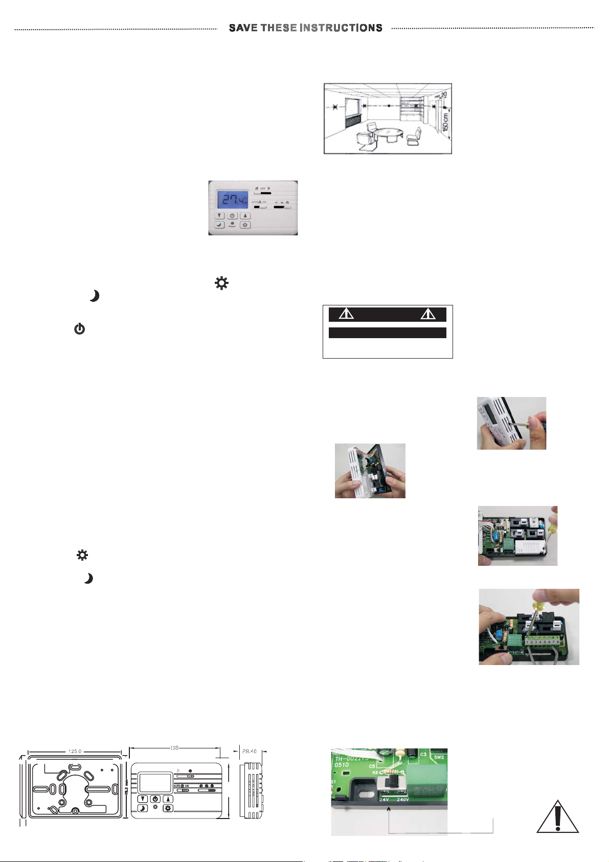
Choose correct location for thermostat
The thermostat should situated in the room where the
heating/cooling is to be controlled.
The place of installation should be chosen so that the
sensors can capture the room temperature as
accurately as possible, without being affected
by direct solar radiation or other heating or cooling
source.
The mounting height should be approximate 1.5
meters above the floor. The unit can be fitted
directly on the wall.
DANGER
Electric Shock Or Fire Hazard
Read allwire sizing, voltagerequirement
and safetyData avoid propertydamage and
personal injury
Disconnect the main
before installation
Technical Data
1.Power supply : Switching power 24 Vac / 240 Vac
2.Display : LCD digital display
3.Output rating : 6A(3A)/250Vac, 60/50Hz.
4.Circuitryconsumption:7VA
5.System switch : Heat-Off-Cool
6.Fan Auto/On selector switch
Auto: Fan turned on or off subject to setpoint.
On : Fan continuous on.
7.Fan speed selector : 3-speed High/Med./Low.
8..Shortestcyclerateprotection:3minutes.
9.Temperature indication :
Celsius /Fahrenheit selectable to users
10.Temperaturecontrolrage:5~35°C(40~113°F)
11.Temperature display range : -10 ~ 50°C (14 ~ 122 F).
12.Temperature adjustment scale : 0.5°C (1.0°F).
13.Comfort setpoint adjustment range:
5 ~ 35°C (40 ~ 113°F), Default 24 C-Cool / 21 C-Heat
°°
14.Economy setpoint adjustment range:
5 ~ 35°C (40 ~ 113°F),Default 27°C-Cool /16°C-Heat
15.Switching differential (Hysteresis) :
Selectable to users (Default 0.4°C/0.8°F)
0.2/0.4/.06/.08/1.0 C ~~~ 0.4/0.8/1.2/1.6/2.0 F
°°
16. Antifreeze protection: 5.0 C° constant
effects only when thermostat is OFF
by Stand-by. Also it effects in Heating only.
17.EEPROM for preserving internal setting in outage.
18.Temperature sensor : NTC 10K Ohm at 25 C.
°
19.Remote temperature sensor : Available.
20.Material : Non flammable plastics.
21.Colour : Standard white or RAL 9010
22.Storage temperature : -10 ~ 60 C.
°
23.Dimension : ( m/m)
OFF
72.3
8
BACK-PLATE
THERMOSTAT
Wiring backplate is provided for installation.
°
To open thermostat for installation
Remove front cover using a
screw to press the cover
latch at top of front cover
Remove cover by holding
base and front cover.
Use screwdriver to remove
terminal protection cover
Mount base with wires
through the holes of the base
than mount the base with
screws(supplied) on the wall.
Install the wires into terminal
blocks, and mount back
terminal block.
Before wiring, you must check your system wiring
diagram. If your system differs from standard
wiring, please check with your local dealer
or consult with professional electrician.
Be certain the voltage
system you plan to
connect this thermostat to,
is consistent with the
switching power
you have chosen.
Page 2
A
V
PROPOSED APPLICATION \ INTERNAL SETTING
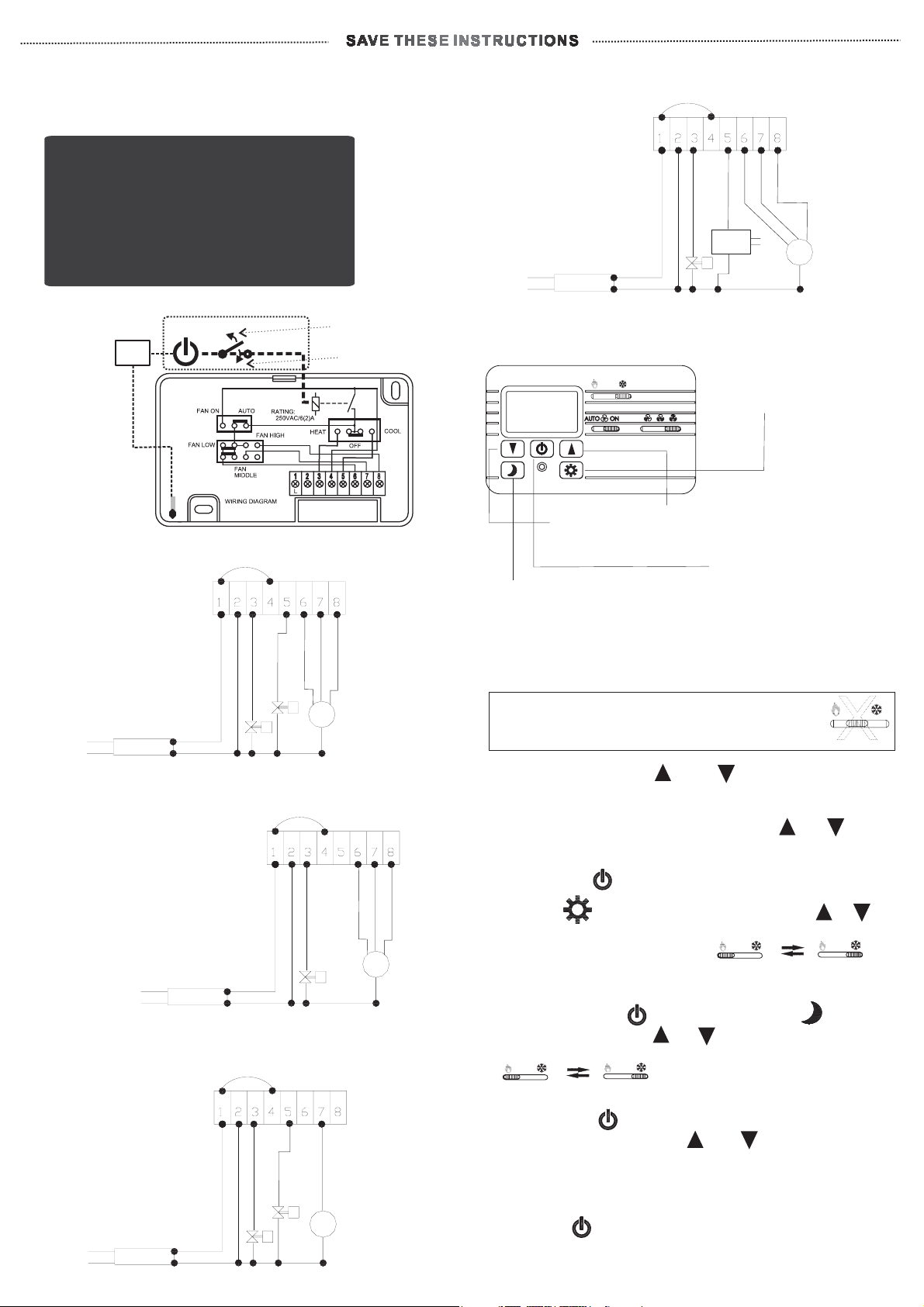
Proposed applications
Stand-By is able to controls ON/OFF at
Stand-By is able to controls ON/OFF at
Terminals
Terminals
3,5,6,7,8
3,5,6,7,8
When Fan-switch is in “AUTO”.
When
3&5only
3
When Fan-switch is in “ON”
When
Fan-switch is in “AUTO”.
& 5 only
Fan-switch is in “ON”
For Heating System
by water, Cooling
by DX System
+ 3-speed fan
control
TRANSFORMER
24 or 240 Vac
Jumpered
Heating Valve
NEUTRAL
LINE
Low
Compressor
Contact
DX
System
Hi
Medium
FAN
Room sensor
commissioning
Heating/Cooling
ON/OFF
to desired setpoints
MCU
For 4 pipes system +
3-speed fan control
TRANSFORMER
24 or 240 Vac
For 2 pipes system +
3-speed fan control
(for Cooling, wire valve
to terminal 5)
TRANSFORMER
24 or 240 Vac
For 2 pipes system +
single-speed
fan control
TRANSFORMER
Standby
TH-0023
Jumpered
Heating Valve
NEUTRAL
LINE
Jumpered
NEUTRAL
LINE
Heating Valve
N
Volt Free Contact
Low
Cooling Valve
Jumpered
Heating Valve
NEUTRAL
LINE
Cooling Valve
Relay Off
Relay Active
Relay
COM
C
H
Medium
Hi
FAN
Medium
FAN
FM.FL.
Low
FAN
FH.
Medium
Hi
Descriptions to buttons on front panel
OFF
Reset
Forward/Backward
or
Incerase/Decrease
Economy
setpoint
Comfort
setpoint
Stand-By
By circuitry design,
to Shut off Heat/Cool
Relay and Fan-Relay
if Fan-modeis in AUTO.
Fan maintains “spinning
if it’s in “ON” mode
Guide to internal settings adjustment
The system selector switch Heat-OFF-Cool
MUST NOT be positioned at the “OFF” while
changing the internal settings.
1. Press and hold both and for 5 seconds to
enter internal setting mode.
2.°C/°F selection shall appear. Press or
to choose.
3.After, press for next internal setting selection.
4.Comfort Setpoint shall appear. Press or
to choose desired setpoint. (Sliding system switch
between Heat-Cool modes
OFF
to set both Heat & Cool Comfort setpoints
before next internal setting.)
5.Press again the to enter Economy Setpoint
selection and using or to choose.
(
Sliding system switch between Heat-Cool modes
OFF
OFF
to set both Heat & Cool Comfort
setpoints before next internal setting.)
6.After, press for choosing Switching-Differential
(Hysteresis). Pressing or to select desired
one among 5 selections.
0.2/0.4/.06/.08/1.0 ° C ~ 0.4/.08/1.2/1.6/2.0°F.
7.All internal setting adjustment is now done.
Pressing , thermostat shall start to operate.
OFF
OFF
24 or 240 Vac
 Loading...