

Page 1
INSTALLATION GUIDE – FREE-STANDING CONVECTORS
1. UNIT DESCRIPTION
A free-standing heater which uses the natural or forced
(with fan) convection heating principle. Since the heater
fully uses physical laws of thermodynamics it represents
one of the most efficient methods of interior heating.
Benefits of free-standing convectors::
High output
Silent operation when the fan is running (models
with fan)
Low hot water consumption
› Short response time
Design
Minimum requirements for operation and mainte-
nance
2. CONTENTS OF THE BOX
3. TECHNICAL PARAMETERS
Use: dry environment according to the specification.
Maximum operating pressure: 1 MPa.
Maximum operating temperature: 110 °C.
Operating medium: water. The use of other media
is prohibited. Water may not be mixed with other
substances, such as antifreeze fluids!
Environment: interiors with temperatures ranging
between +5 °C and +40 °C.
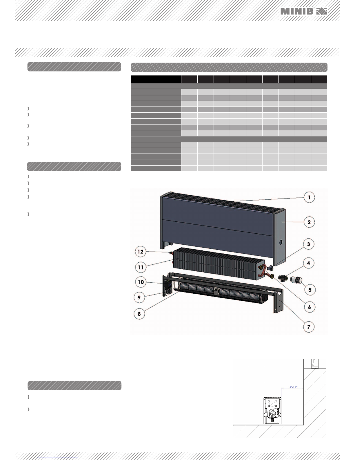
1. CONVECTOR GRILLE – a design piece on the convector. It must not be covered!
2. OUTER BODY OF THE CONVECTOR – aluminum
convector body with plastic covers.
3. SCREW FITTING – a valve that controls/adjusts heating water flow.
4. AXIAL RADIATOR VALVE – a valve used for flow
regulation.
5.
THERMOSTATIC HEAD – used for manual regulation.
6. CONNECTING SCREW FITTING – for connecting
valves; gasket (O-ring) is to be installed in it.
7. SUPPORTING FRAME OF THE CONVECTOR – supporting element for heat exchanger and fan (models with fan)
8. FAN – used for forced convection (model with fan).
9. CABLE GROMMET – intended for power supply cable for the control unit (models with fan).
10. EB CONTROL UNIT – fan motor control unit (models with fan).
11. HEAT EXCHANGER – copper pipes with pressed-
-on aluminum fins through which the heating water
flows. The exchanger design depends on the convector model.
12. AIR VENT VALVE – for venting (bleeding) the convector heat exchanger.
Contents of the box SK1 SK2 SU1 SU2 SP 1/4 SP 2/4 SW 250 SW 420 SPO
Convector
Plastic cover 2 2 2 2 2 2 2 2 2
Grille 1 1 1 1 1 1 1 1 1
Convector body 1 1 1 1 1 1 1 1 1
Bearing element 1 1 1 1 1 1 1 1 1
Heat exchanger 1 1 1 1 1 1 1 1 1
Fan 1-2 1-2 - - - - - - -
EB control unit 1 1 - - - - - - -
Cable grommet 1 1 - - - - - - -
Accessories
Axial radiator valve 1 1 1 1 1 1 1 1 1
Thermostatic head 1 1 1 1 1 1 1 1 1
Control screw fitting 1 1 1 1 1 1 1 1 1
O-RING 18X2 NBR70 2 2 2 2 2 2 2 2 1
Valve connection template 1 1 1 1 1 1 1 1 1
4. BEFORE INSTALLATION
Select the correct convector type (with fan / wi-
thout fan) from the catalogue – see paragraph 4.1.
Select the correct convector position and location
– see paragraph 4.2.
4.1 Suitable Convector Type
Decide whether the convector will act as the main
source of heat, or an additional heating element or, if
applicable, a heat barrier.
As the main source of heat in your apartment / room,
the convector should sufficiently cover the entire thermal loss of the room. Therefore always choose a heating unit with a capacity that is higher than the thermal
loss of your apartment, room, or other areas.
All convectors are designed for dry environment, i.e., an
environment where the average annual relative humidity
does not exceed 75 %. A wet environment is an environment where such average annual value is equal to or
greater than 75 % or where the convector is exposed to
direct contact with water. In terms of convector selection,
a dry environment is in general any environment where
no precipitation of vapor occurs in the convector unit.
4.2 Convector Position
The free-standing convector made by MINIB is to be
floor-mounted. Place the convector so that it does not
disturb the overall aesthetic experience of the room.
We recommend leaving a 50-150 mm space between
the convector and the wall – Figure 2. Never cover
the top grille – this would result in flow reduction and
a considerable decrease in the convector output.
FIG. 1: COMPONENTS OF THE FREE-STANDING CONVECTOR:
FIG. 2: Convector position (model with fan / without fan).
Page 2
HEAD OFFICE
MINIB,a.s.
Střešovická 465/49, 162 00 Prague 6
Czech Republic
Tel.: +420 220 180 780
Fax: +420 220 180 779
E-Mail: office@minib.cz
www.minib.cz
PRODUCTION
Manufacturing plant of MINIB,a. s.
Býkev u Mělníka 84, 276 01 Býkev
Czech Republic
WWW.MINIB.CZ
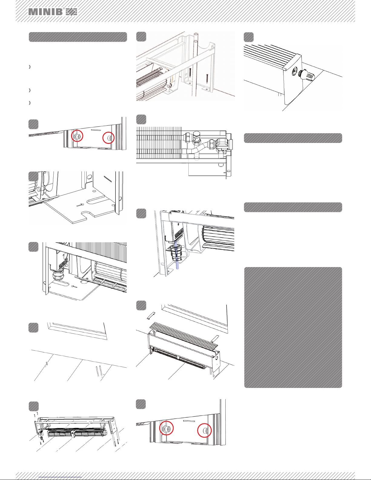
5. INSTALLATION
Free-standing convectors are designed for installation on the floor. Please read the following instructions
before you start.
For floor installation use the template to plan the
exact position of the inlet/outlet heating water
pipe, mounting points (in models with fan) of the
power supply (cable).
Fix the free-standing convector using the mounting
accessories supplied by MINIB a.s..
A correctly installed convector is in horizontal po-
sition and fixed in the full width of the leg.
7. VENTING THE UNIT
Vent (bleed) the unit using the air vent valve during
the first use as necessary. In free-standing convectors, the air vent valve is located on the opposite side
of the water inlet/outlet side on the heat exchanger.
For additional options see the catalogue or visit:
http://www.minib.com/
6. CONNECTION OF THE FITTINGS
Connect the fittings using the supplied standard accessories.
The axial radiator valve is connected to the water inlet point into the convector. The control screw fitting
is installed on the outlet pipe. Insert the O-rings between the axial radiator valve / control screw fitting
and the heat exchanger. Use gaskets for all the other
connections.
FIG. 6: Drill the holes, install the heating water inlet and return
pipes, and the power supply cable in models with fan.
TEMPLATE
TEMPLATE
FIG. 3: For all models. Loosen the screws (do not remove the
screws completely!) on both legs of the convector body and
remove the top cover, the plastic covers, and the grille.
FIG. 8: For all models. Fix the convector frame using screws.
FIG. 13: For all models. Connect the thermostatic head.
FIG. 12: For all models. Tighten the screws on the convector
legs.
FIG. 4: Use the template for the relevant model to mark the
inlet pipe, return pipe, and fixing screw positions.
FIG. 5: On the opposite side, use the template to mark the
convector fixing holes and the power supply cable location in
models with fan.
1.
2.
3.
4.
FIG. 9: For all models. Install the heat exchanger and connect
the fittings – see paragraph 6. Check tightness of the connections. The inlet is to be equipped with the axial valve. The
control screw fitting is to be used on the outlet pipe.
FIG. 10: For models with fan. Connect the cable through the
grommet to the control unit according to the instruction and
the control type selected. Check function of the fan.
5.
10.
11.
6.
7.
8.
FIG. 11: For all models. Replace the cover, grille and side
profile covers on the convector frame.
9.
FIG. 7: For all models. Insert screw anchors and place convec-
tor supporting frame.
 Loading...