

Page 1
INSTALLATION GUIDE - SK CONVECTORS
1. UNIT DESCRIPTION
A skirting-type heating unit which uses the convection principle. Since the heater fully uses physical laws
of thermodynamics it represents one of the most efficient methods of interior heating.
Benefits of skirting convectors with fan:
High output
› Possibility of using forced convection for heating
(with fan)
› Silent operation
› Low hot water consumption
› Very short response time
› Design
› A great advantage of these convectors is the
possibility of installation in a skirting (under kitchen
cabinets, stairs, wardrobes, etc.). This advantage
is particularly practical in applications where we
do not want to disturb the aesthetic experience
of the interior with wall-mounted or free-standing
convectors or other heating units, and where suffi-
cient heating output is required at the same time.
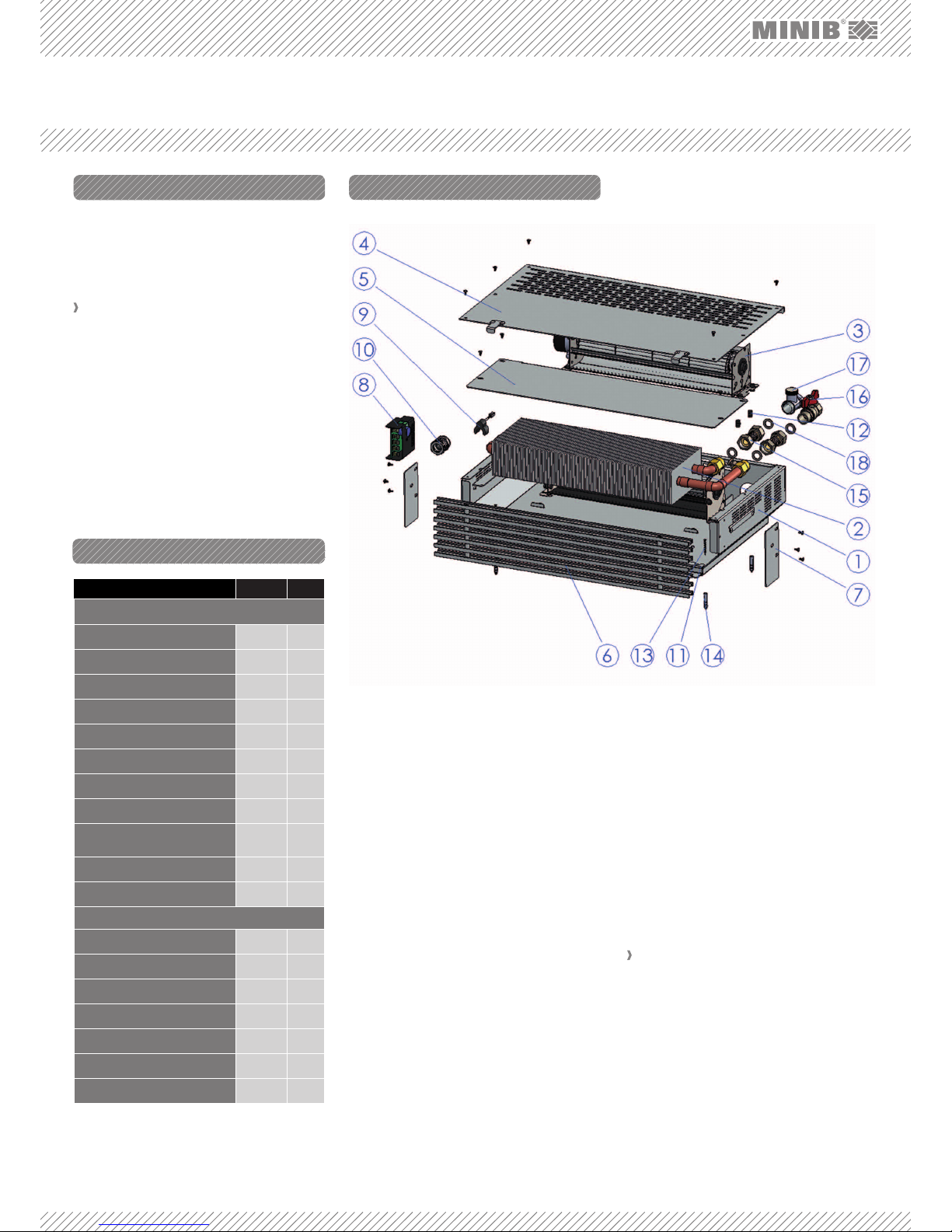
FIG. 1: COMPONENTS OF THE SKIRTING CONVECTOR:
2. CONTENTS OF THE BOX
3. TECHNICAL PARAMETERS
1. TROUGH – an all-aluminum structure which holds
all components (AIMg3).
2. HEAT EXCHANGER – copper pipes with pressed-
-on aluminum fins through which the heating water
flows.
3. FAN – used for forced convection.
4. METAL COVER – used as a lid of the trough (position 1) and protects all components located in it
from damage.
5. DIRECTIONAL METAL PLATE – improves the convector output thanks to ideal air flow around the
heat exchanger.
6. FRONT GRILLE – the only visible part after installation.
7. GRILLE SIDE PLATE – limits the space (horizontally)
for placement of the grille.
8. EB CONTROL UNIT – fan motor control unit.
9. TEMPERATURE SENSOR – heat exchanger temperature sensor
10. CABLE GROMMET – intended for 12VAC power
supply cable.
11. GUIDE BAR – used for exact positioning of the convector.
12. RUBBER ANTI-VIBRATION RING – used for attenuation of vibrations and for mounting of the metal
covers and fan modules.
13. SCREW – for fixing the guide bars (position 11) to
the floor, step.
Contents of the box Position SK
Convector
Trough 1 1
Heat exchanger 2 1
Fan 3
1
Metal cover 4
1
Directional metal plate 5
1
Front grille 6
1
Grille side plate 7
2
EB control unit 8
1
Temperature sensor of the
exchanger
9
1
Cable grommet 10
1
Guide bar 11
2
Accessories
Anti-vibration pad 12 4
Wood screw 3 x 30 13 4
Screw anchor 3
14 4
Hose G ½´´ - 41 mm
15 2
Ball valve – straight
16 1
Control screw fitting – straight
17 1
Gasket KLINGERSIL C4400
18 4
Each position in the table corresponds to Figure No.
1 – see next page.
14. SCREW ANCHOR – for fixing the screw in concrete floor.
15. HOSE – the bellows hose is a stainless hose intended for fitting connection to the convector exchanger.
16. STRAIGHT BALL VALVE – a valve used to shut off
the heating water supply to the convector.
17. CONTROL SCREW FITTING - a valve that controls/
adjusts heating water flow.
18. GASKET – seals joints between valves, hoses,
and exchangers (KLINGERSIL C4400). MINIB, a.s.
recommends this sealing as the optimal sealing
solution because other materials (rubber, NBR,
silicon) do not provide the required sealing characteristics.
Use: dry environment, according to the specification.
› Maximum operating pressure: 1 MPa.
› Maximum operating temperature: 90 °C.
› Operating medium: water. The use of other media
is prohibited. Water may not be mixed with other
substances, such as antifreeze fluids!
› Environment: interiors with temperatures ranging
between +5 °C and +40 °C.
› Power supply: 12 V AC from a suitable transfor-
mer for the given environment and convector fan
types.
Page 2
4. INSTALLATION
5. CONNECTION OF THE FITTINGS
Consult the convector position with an expert or
your designer.
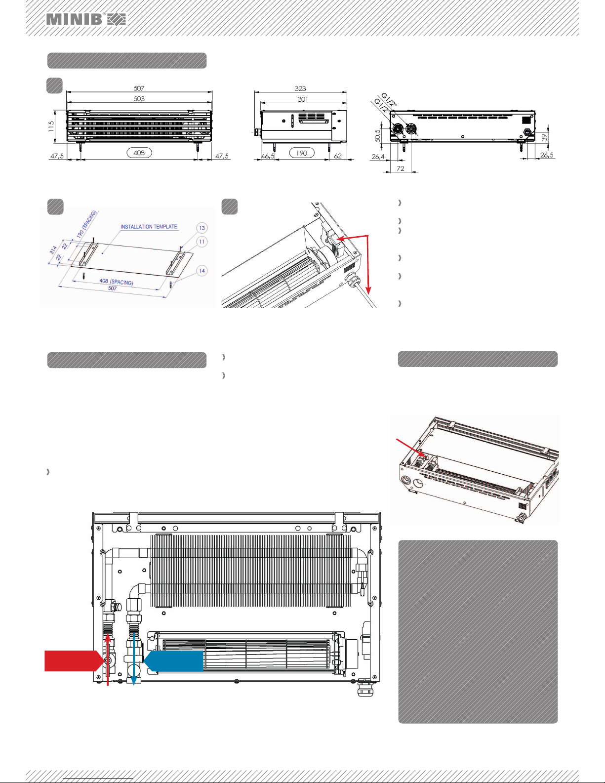
For main dimensions of the convector see Figure 2.
The heat exchanger and the distribution pipes
must be connected using the supplied stainless
steel hoses.
A correctly installed convector is in horizontal po-
sition.
Install the guide bars (position 11) using the instal-
lation template (see Figure 3) before you place the
convector.
Install the power supply cable in the installed con-
vector; for the fan motor connection see Figure 4.
For safety reasons check whether the power supply cable is not live.
Connect the fittings using the supplied standard ac-
cessories (direct connection – in the rear part of the
convector).
Connect individual inlet and outlet valves. The water
inlet to the convector is provided with a ball valve
(standard supply) enabling the shutting off of the heating water supply in the event of a failure. The control
screw fitting is installed on the outlet pipe. Gaskets
must be used in all connections.
Use the supplied flexible stainless hoses (bellows
hose) to connect the heat exchanger.
Vent (bleed) the unit using the air vent valve during the
first use as necessary. In skirting convectors, the air
vent valve is located on the water inlet side on the heat
exchanger fitting.
FIG. 2: Minimum installation dimensions: height 117 mm; width 510 mm; depth – heating water supply must be taken into account.
FIG. 3: The installation template is symmetrical; the longer
edge (507 mm) copies the front surface of the convector
(front grille).
FIG. 6: Air vent valve
1.
2.
FIG. 4
3.
HEAD OFFICE
MINIB,a.s.
MINIB,a.s.
Střešovická 465/49, 162 00 Prague 6
Czech Republic
Tel.: +420 220 180 780, fax: +420 220 180 779
E-Mail: office@minib.cz, www.minib.cz
PRODUCTION
Manufacturing plant of MINIB,a. s.
Býkev u Mělníka 84, 276 01 Býkev
Czech Republic
WWW.MINIB.CZ
Inlet - ball valve
Outlet - control
screw fitting
FIG. 5: Direct heating water connection – standard design (standard accessories).
Stainless hoses are designed to withstand a maxi-
mum pressure of 1.0 MPa.
Hoses must not be stretched, subjected to tensile
stress, or otherwise deformed.
Water inlet: The water inlet pipe is always equipped
with a ball valve (included in the standard supply).
Outlet (return pipe): The screw fitting is always connected to the return pipe.
Note: The skirting-type convector must be connected to
the distribution pipes using hoses with sufficient length
which will allow the convector to be pulled out to allow
maintenance work, if necessary, on any part of the convector. These hoses are not included in the supply.
6. VENTING THE UNIT
 Loading...