

Page 1
INSTALLATION GUIDE – WALL-MOUNTED CONVECTOR NK1
1. UNIT DESCRIPTION
A wall-mounted NK1 heating unit equipped with fans.
Since the heater fully uses physical laws of thermodynamics it represents one of the most efficient methods
of interior heating.
Benefits of heating convectors:
High output
Silent operation or low noise for units with fan
Lightweight compared to heating units with similar
output which use radiation principle
Low hot water consumption
Short response time
Design
Minimum requirements for operation and mainte-
nance
A great advantage of these convectors is the small
required installation space. This is beneficial par-
ticularly in a situation where the heating units are
used in interior renovation and replacement of old
heaters with new ones and in situations where
sufficient heating output is required.
Contents of the box Position NK1
Convector
Plastic cover
7 2
Grille
6 1
Convector body
5 1
Support part
13 1
Heat exchanger
3 1
Grille support
8 1
Cable grommet
2 1
Fan
15 1-2
EB control unit
1 1
Accessories
Axial radiator valve 10 1
Thermostatic head 11 1
Control Screw fitting - angular ½´´
12 1
Flexible stainless steel hose - 1
3. TECHNICAL PARAMETERS
Use: dry environment, depending on the specifica-
tion.
Maximum operating pressure: 1 MPa.
Maximum operating temperature: 110 °C.
Operating medium: water. Water may not be mixed
with other substances, such as antifree¬ze fluids!
Environment: interiors with temperatures ranging
between +5 °C and +40 °C
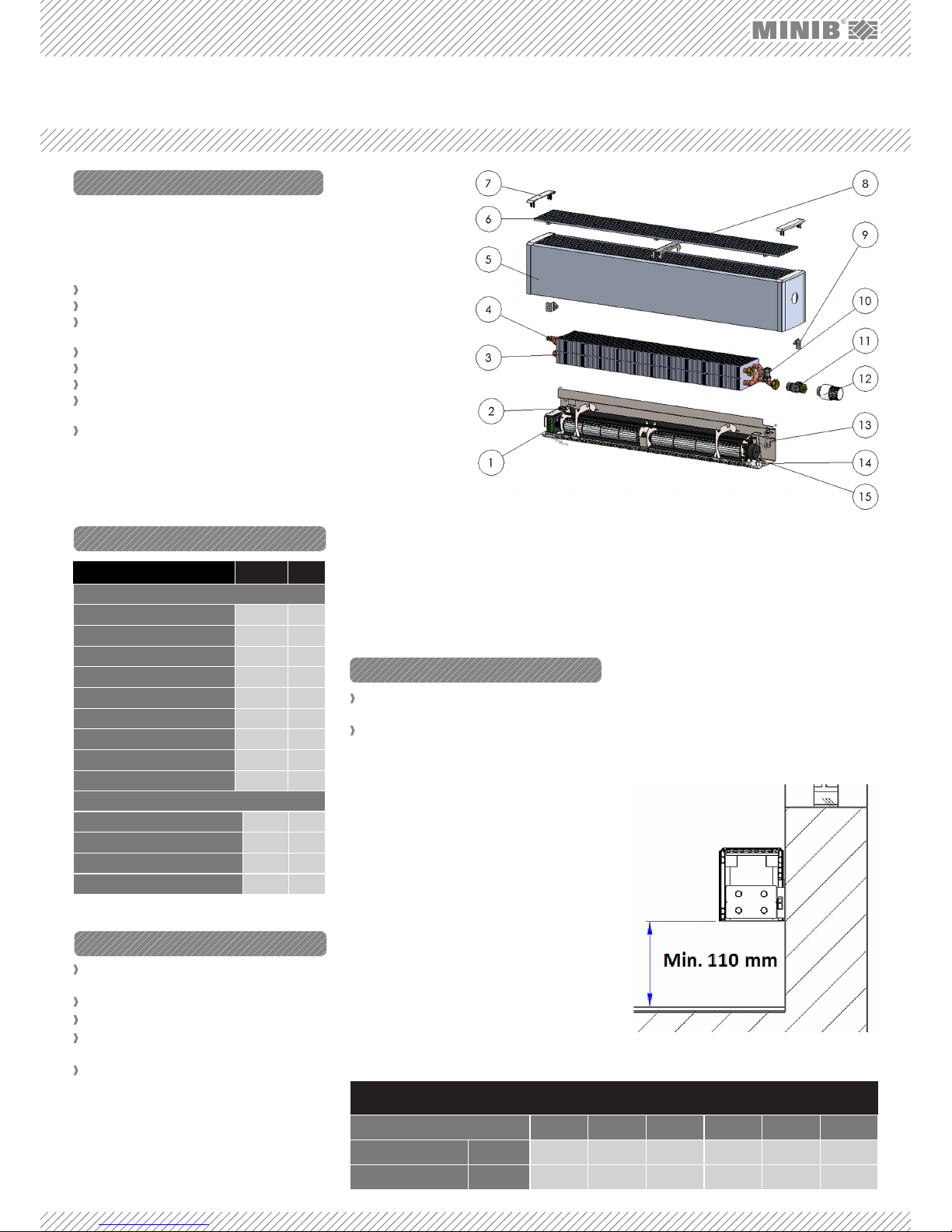
1. EB CONTROL UNIT – fan motor control unit.
2. CABLE GROMMET – intended for cable installation
to the control unit.
3.
HEAT EXCHANGER – copper pipes with pressed-on
aluminum fins through which the heating water flows.
Each position in the table corresponds to Figure No. 1.
Select the correct convector type (with or without
fan) from the catalogue – see paragraph 4.1.
Select the correct convector position and location
– see paragraph 4.2.
4.1 Suitable Convector Type
Decide whether the convector will act as the main
source of heat, or an additional heating element or, as
the case may be, as a heat barrier.
As the main source of heat in your apartment / room,
the convector should sufficiently cover the entire
thermal loss of the room. There¬fore, always choose
a heating unit with a capacity that is higher than the
thermal loss of your apartment, room, or other areas.
All wall-mounted convectors are designed for dry
environment. A dry environment is an environment
where the average an¬nual relative humidity does
not exceed 75%. A wet environment is an environment where such average annual value is equal to or
greater than 75% or where the convector is exposed
to direct contact with water. In terms of convector
selection, a dry environment is in ge-neral any environment where no precipitation of vapor occurs in the
convector unit.
FIG. 1: COMPONENTS OF THE NK1 CONVECTOR
Design of the heat
exchanger differs
depending on the
convector model.
4. AIR VENT VALVE
– used for venting
(bleeding) the convector.
5. CONVECTOR BODY
– aluminum convector body.
6.
CONVECTOR GRILLE
– a design piece
within the convector. It must not be
covered!!!
7. PLASTIC COVER –
used for attaching
the grille to the convector body.
8. GRILLE SUPPORT –
for supporting the
convector grille.
13. CONVECTOR SUPPORT PART – a fixing part of the
wall-mounted convec¬tor, supporting part for the
convector body and heat exchanger.
14. RUBBER ANTI-VIBRATION PAD – for flexible
mounting of the fan module.
15. FAN – used for forced convection.
9. ADJUSTING SCREW – used for vertical positioning of convector on the wall.
10. CONTROL SCREW FITTING – a valve that controls
/ adjusts the heating water flow.
11. AXIAL RADIATOR VALVE – a valve used for flow
regulation.
12.
THERMOSTATIC HEAD – used for manual regulation.
4.2 Convector Position
Wall-mounted convectors MINIB are intended for installation on the wall below window frames or sills.
Make sure to follow the principle that the distance
from the floor should never be less than 110mm (Figure
2). Never cover the upper grille of the convector – this
would result in flow reduction and a considerable decrease in the convector output.
2. CONTENTS OF THE BOX
4. BEFORE INSTALLATION
FIG. 2: For all models – convector position.
Dimensions for marking of mounting holes
Convector length 900 1,000 1,250 1,500 1,750 2,000
NK1
A 730 840 1,067 1,297 1,597 1,824
B 684 784 1,011 1,241 1,541 1,768
Page 2
1.
2.
3.
4.
5.
6.
7.
8.
9.
9.
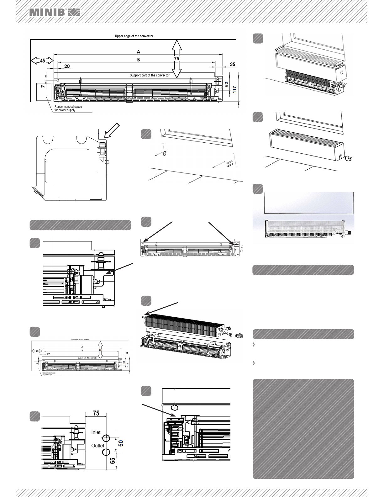
Connect the lines using the supplied standard accessories. Connect the outlet line of the heating water and
the fitting using the supplied flexible hose. An axial radiator valve is connected to the water inlet of the heat
exchanger. Control fitting is installed on the outlet line.
Insert O-rings between the axial radiator valve / control fitting and the heat exchanger. Use gaskets for all
the other connections.
6. CONNECTION OF THE FITTINGS
HEAD OFFICE
MINIB,a.s.
Střešovická 465/49, 162 00 Prague 6
Czech Republic
Tel.: +420 220 180 809, fax: +420 220 180 779
E-Mail: export@minib.cz, www.minib.cz
PRODUCTION
Manufacturing plant of MINIB,a. s.
Býkev u Mělníka 84, 276 01 Býkev
Czech Republic
WWW.MINIB.CZ
7. VENTING THE UNIT
FIG. 4: Screw the levelling screw of the support part to a central
position.
FIG. 5: Follow the instructions and installation dimensions
specified in paragraph 4.2. in Fig. 3. Mark holes for screw
anchors and for the connection of the power supply cable, if
applicable (for models with a fan).
FIG. 6: Mark the position of the pipes.
FIG. 7: Drill holes for fixing, for the pipes and the power supply
cable, if applicable (for models with a fan), install screw
anchors.
FIG. 8: Using the screws, attach the support part in the
prepared screw anchors on the levelling screw and on the
opposite end. Do not tighten. Adjust the support part into
horizontal position, using the adjusting levelling screw and
tighten the screws.
FIG. 9: Position the heat exchanger on the supports, install the
pipes and connect valves as specified in paragraph 6.
FIG. 10: Connect the cable through the grommet into the
control unit according to instructions and the type of control
selected. Check the function of the fan.
FIG. 11: Place the body, the grille and the covers on the convector
support part.
FIG. 12: Connect the thermostatic head.
FIG. 13: Set the axle alignment of the unit cover with the wall
using the adjusting screws which are located in the lower
part of the convector body.
FIG. 3a: Upper edge of the NK1 support part - side view.
5. INSTALLATION
Vent (bleed) the unit using the air vent valve dur-
ing the first use as necessary. The air vent valve is
located on the heat exchanger – see Fig. 9.
For additional options see the catalog or visit:
http://www.minib.com/
FIG. 3: NK1 (for upper edge see Fig. 3a).
Air vent valve
 Loading...