

Page 1

CONTROL, ACCESSORIES,
INSTALLATION MANUALS
Page 2

ABOUT US
ABOUT THE COMPANY
MINIB,a.s. is a Czech business through and through, and it ranks
among the leading manufacturers of convectors in the Czech Republic. It currently exports to thirty countries in Europe, Asia, Australia,
and America.
Since 1999, MINIB has been systematically innovating its production technology and its products and has invested considerable sums
in proprietary development and design, with the goal of offering our
customers solutions that are mature both from the technical and esthetic points of view.
MINIB's business is economically soand and the company consistently turns a profi t. This allows us to invest in R&D, technology, and
above all, human capital, so as to ensure our long-term prosperity.
ABOUT THE MANUFACTURING PROCESS
The manufacturing facility is located in Býkev near Mělník and has
excellent transport connections. It is furnished with state-of-the-art
production technology. Most manufacturing operations are carried
out on CNC machines, which allows us to accommodate even the
most sophisticated wishes of our exacting customers.
In response to individual calls for customization, we are able to create a wide variety of non-standard, one-of-a-kind products that satisfy
specifi c needs.
All products are made from high-grade material with a useful life of
many years, which is why we offer a 10-year warranty on heat exchangers and our stainless-steel convector vats.
MINIB holds an ISO 9001:2008 certifi cate in addition to numerous utility models and patents.
The entire range of products is submitted to testing in the independent, accredited test chamber of HEATEST, s.r.o. pursuant to the European Standard EN 442-2, which is why we are able to guarantee the
advertised heating and cooling output.
ABOUT THE PRODUCTS
MINIB's production portfolio consists of over 70 convector types.
Customers can thus choose the right convector for any interior.
The main advantage of convectors is that they are effi cient, modern,
economical, and esthetic heaters suitable for both dry and humid
environments. Signifi cant power savings are achieved thanks to
low water requirements for the immediate heating or cooling of a given area. This leads to low consumption of electricity required for
its heating. In addition to water and energy savings, a great heating
and cooling dynamics is also important. The space saving design is
another important feature of these products. Our convectors do not
disturb interior esthetics, have a modern design, and - last but not
least - are safe thanks to their 12V power supply.
The product range comprises various types of convectors:
FLOOR convectors without fans that work on the natural con-
vection principle. Convectors with fans utilize the principle of
forced convection.
FREE STANDING AND WALL MOUNTED convectors with and
without fans are also available. Heating benches with granite and wooden top panels are available for humid environments (swimming pools, bathrooms).
DESIGN convectors are a unique patent series that use both
the convection and heat radiation principle for heating.
These convectors have aluminum composite front panels
available in a number of modern designs from smooth glass
with various colors or from glass with sand blasted decorations. The company also offers granite front panels.
MINIB can satisfy any individual, non-standard requirements of
its customers such as angular or arc-shaped convectors with
various connections and tailor them to their demands. MINIB
emphasizes high user comfort. All products place low demands
on installation and maintenance.
Numerous accessories are available for individual convector types.
MINIB products have won a number of national and foreign awards.
Page 3
26
1. UNIT DESCRIPTION
This is a fl oor heating unit that works on the convection principle. The unit fully uses the laws of physics in the area of thermodynamics, representing one of the most effi cient means of interior heating.
BENEFITS OF FLOOR CONVECTORS WITH FAN:
high output,
possibility of heating using natural or forced (with fan) convection ,
low fan noise or no noise at all in natural convection mode, light weight compared to other heating units with similar output,
low hot water consumption,
very short response time,
design,
minimal operation and maintenance requirements,
a great advantage of the fl oor convectors is the possibility of embedding them in interior fl oors. This advantage is benefi cial in places where
we do not want to disturb the aesthetic appearance of the interior by wall mounted or free-standing convectors or other heating units, but
where suffi cient heating output is required.
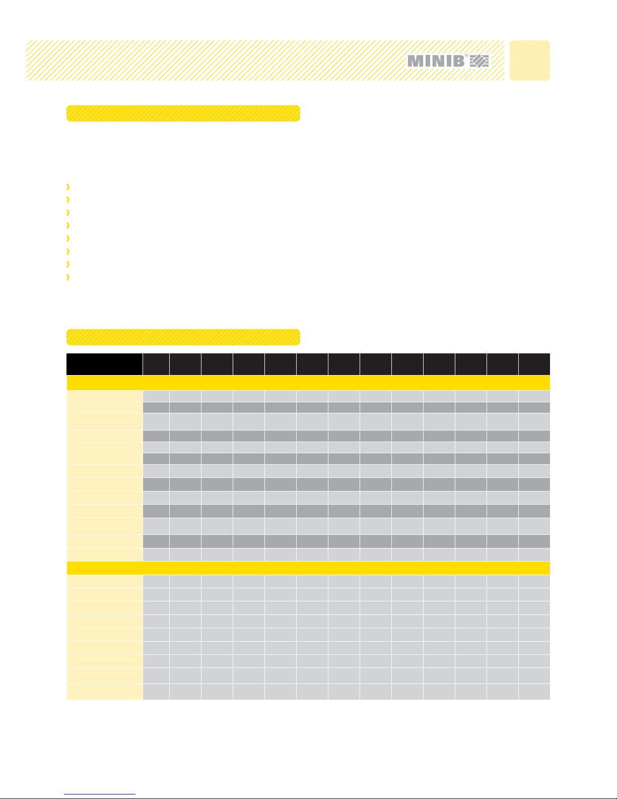
2. PACKAGE CONTENT
* Forms part of the vat
1)
Braces: 1 brace for lengths up to 1500 inclusive, 2 braces for lengths between 1750 and 2000 and 3 braces for lengths between 2500 and 3000
2)
decorative frame consists of 4 pieces - 2 short segments and 2 long segments
3)
There are +2 pieces for lengths over 2000
4)
Number of fan motors depends on convector length (1 to 4 fan modules).
PACKAGE CONTENT Position
KT
KT110
KO
KT0
KT1
KT2
KO2
KT 3
KT3 105
T50, T60,
T80
TO 85
MT
MO
HC HCM HC4p HCM4p
Convector
Vat 1111111111111
Exchanger holder 2 2-4 * 2-4 2-4 * * * * 2-4 * * *
Side holder of the
exchanger
32-4-2-42-4----2-4---
Exchanger 4
111111111111
Anti-vibration mounting 5
888888888888
Cover panel 6
1+1 1+1 1+1 1+1 1+1 1+1 1+1 1+1 1+1 1+1 1+1 1+1
Brace
1)
7 1-3 1-3 1-3 1-3 1-3 1-3 1-3 1-3 1-3 1-3 1-3 1-3
Decorative frame
2)
8111111111111
Fan
4)
17 1-3 1-3 1-3 1-3 1-3 1-4 1-3 1-3 1-3 1-3 1-3 1-3
EB control unit 18 1 11111111111
Exchanger temperature
sensor
19111111111111
Cable grommet 20 1 11111111111
Fan fi lter 21 1 1 - 1 - - - 1 - 1 1 1
Accessories
Anti-vibration mounting 5 4 44444444444
Anchoring footing
3)
9 4-6 4-6 4-6 4-6 4-6 4-6 4-6 4-6 4-6 4-6 4-6 4-6
Screw M8x50 3) 10 4-6 4-6 4-6 4-6 4-6 4-6 4-6 4-6 4-6 4-6 4-6 4-6
Wood screw 3x30 3) 11 4-6 4-6 4-6 4-6 4-6 4-6 4-6 4-6 4-6 4-6 4-6 4-6
Dowel 3
3)
12 4-6 4-6 4-6 4-6 4-6 4-6 4-6 4-6 4-6 4-6 4-6 4-6
Hose G1/2“ – 65 mm 13 2 22222222222
Straight valve 14 1 11111111111
Screw fi tting - straight 15 1 11111111111
Sealing KLIGERSIL C4400 16 4 44444444444
Individual positions in the table correspond to Figure No. 1 - see previous page.
installation manuals - fl oor convectors with fan
Page 4
27
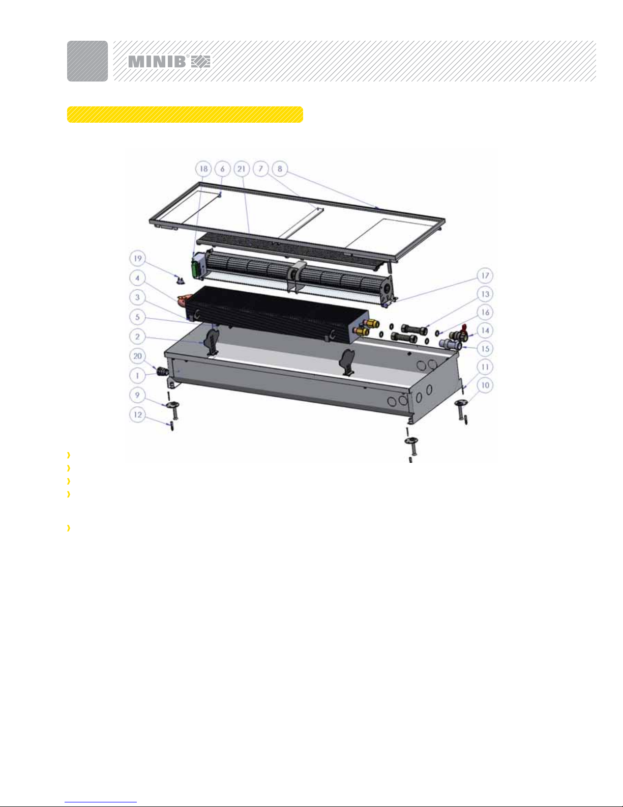
3. TECHNICAL PARAMETERS
Figure 1: COMPONENTS OF FLOOR CONVECTOR WITH FAN:
usage: dry or wet premises according to specifi cations,
maximum operating pressure: 1.0 MPa,
maximum operating temperature: 95 °C,
operating medium: water. The use of other media is prohibited.
Water may not be mixed with other substances, such as non-freeze liquids!
environment: interiors with temperatures between +5°C and
+40°C.
1. VAT - stainless metallic vat according to type designed for dry or
wet environment. Dry environment: stainless steel AISI 304, wet
environment: AISI 316.
2. EXCHANGER HOLDER - Supports the exchanger and keeps it in correct vertical position.
3. EXCHANGER SIDE HOLDER - limits the space between the convector vat and the exchanger.
4. EXCHANGER - copper pipes with pressed-on aluminum fi ns through
which the heating water fl ows.
5. RUBBER ANTI-VIBRATION MOUNTING - intended for vibration attenuation and for cover panel mounting.
6. COVER PANEL - cover panel covers the blind space. The second
cover panel covers the water connection.
7. BRACE - metallic brace maintains convector vat shape during installation.
8. CONVECTOR FRAME - the frame is a design element and should
be perfectly aligned with fi nal fl oor. Maximum height difference
should be (0-1 mm).
9. ANCHORING FOOTING - intended for convector mounting and
accurate positioning in rough fl oor.
10. POSITIONING SCREW - intended for fi ne positioning of the convector before concreting.
11. WOOD SCREW - fi xing footing attachment to the fl oor.
12. DOWEL - screw fi xing in concrete fl oor.
13. HOSE – the bellows hose is a stainless hose intended for fi tting
connection to the convector exchanger.
14. STRAIGHT VALVE - can be either thermostatic or ball straight valve. This valve shuts off the water supply to the convector.
15. SCREW FITTING - a valve that controls / adjusts heating water fl ow.
16. SEALING - seals joints between valves, hoses, and exchangers
(KLEGERSIL C4400). MINIB, s.r.o. recommends this sealing as an
optimum sealing solution, as other materials (rubber, NBR, silicon)
do not have suffi cient tightness upon suffi cient tightening and because they are deformed by tightening forces.
17. FAN - intended for forced convection.
18. EB CONTROL UNIT - fan motor control unit.
19. TEMPERATURE SENSOR - exchanger temperature sensor.
20. GROMMET - intended for 12VAC power supply cable.
21. FILTER - the purpose of the fi lter is to protect the fan modules against larger particles. It also protects the fan against dust. Convector with fi lters can be provided with a walk-on grille with greater
bar spacing.
floor convectors with fan - installation manuals
Page 5

28
4. BEFORE INSTALLATION
Use the catalogue to choose a suitable convector for wet or dry
environment - see paragraph 4.1.
Select correct convector position - see paragraph 4.2.
Leave enough space for placement and installation - see paragra-
ph 4.3. Consider using thermal insulation, anti-vibration foil, or bra-
ces into
hollow fl oors - see paragraph 4.4.
Do not forget drainage pipes or other condensate removal sys-
tems - see paragraph 4.5.
4.1 Suitable Convector Type
Decide whether the convector will act as the main source of heat, an
additional heating element or a thermal barrier.
As the main source of heat in your apartment / room, the convector
should suffi ciently cover the entire thermal loss of the room. Therefore,
choose a heating unit with a capacity that is higher than the thermal
loss of your apartment, room, or other premises.
Make sure that you have enough space for convector installation - both
from the wall (window) and in the fl oor (see paragraph 4.3).
Determine whether the convector will be used in a dry or wet environment. A dry environment is an environment where the average
annual relative humidity does not exceed 85%. A wet environment is
an environment where such average annual value is equal or greater
than 85%. In terms of convector selection, a dry environment is in general any environment where no precipitation of vapor occurs in the
convector unit. Convectors intended for a wet environment have more
resistant stainless material and a feature for condensate drainage.
4.2 Convector Position
Consult the convector position with an expert or your designer.
MINIB fl oor convectors are intended for embedding in fl oors in order
to avoid disturbance to the overall aesthetic appearance of the room.
If the convector is intended to be the main source of heat, it must be
placed with a heat exchanger in the room (Figure 2). If the convector
serves as an additional source of heat or as a thermal barrier, it is
placed with a heat exchanger towards the window (Figure 3). If the
convector is equipped with a heat exchanger over its entire width, it
is recommended that the convector be positioned with the fan facing
into the room.
4.3 Installation Space
MINIB, s.r.o. recommends leaving suffi cient space for convector
installation. For installation in older fl oors, during reconstruction, or
whenever suffi cient space is not available, the dimensions of the installation hole should be equal to the convector height + at least 20
mm. The width and/or length (if only 1 convector is concerned) of the
installation hole should correspond to the convector width (length) +
at least 60 mm - see Figure 4. Clearance around the convector should
provide enough space for the connection of water, cabling, and convector embedding in concrete. For new fl oors, MINIB recommends at
least +100 mm of free space around the convector; the height remains
identical to the previous case (H + at least 20 mm).
The position and location of the convector fully depend on the client's
requirements, particularly, what and how they need to heat or cool.
MINIB, s.r.o. recommends installing convectors acting as the main
source of heat under windows with a heat exchanger into the room.
The recommended distance from the wall is 200 – 350mm. If the
customer wishes to use the convector as an additional source of heat
only (i.e., the convector does not serve as the main source of heat),
the heat exchanger can be turned towards the window. The exchanger location on the window side is recommended in cases where the
convector is used as an additional source of heat or when it acts as a
thermal barrier in front of the window.
4.4 Principles of Convector Installation in Floors
MINIB fl oor convectors are intended for installation in solid or hollow
fl oors where certain principles apply. Before you start, please read
the following instructions.
At your own discretion (parquet, fl oating, or wooden fl oors), install
thermal insulation on the outside of the convector vat on the heat
exchanger side. (Figure 6).
If the convector is installed at a frequented spot where people of-
ten step on the cover grille or walk past the convector, it is recommended that anti-vibration foil be used to reduce structure-borne
noise, particularly, in multi-story buildings (Figure 7).
installation manuals - fl oor convectors with fan
Figure 4: B - maximum width of convector; L - convector length; H - convector
height (without adjustment legs)
Recommended MINIMUM clearance for installation: B + 60 mm; L + 60 mm;
H + 20 mm
Figure 2: Convector with exchanger
in the room as the main source of
heat.
Figure 3: Convector with exchan-
ger towards the window as an
additional source of heat.
window
exchanger
window
exchanger
Figure 3-1
Page 6

29
4.4.1 Hollow Floors – Principles of Installation of Floor Convectors
with Fan:
When installing a convector in a hollow fl oor, it is necessary to use
hollow fl oor braces outside the convector unit in order to ensure
its stability (Figure 5).
Anti-vibration foil must be used for convectors with a fan installed
in hollow fl oors
Decide on the use of thermal insulation at your own discretion.
Use thermal insulation depending on the type and characteristics
of the fl oor. If the heat exchanger is situated along one side of the
convector, it is suffi cient to apply the insulation on that side. If the
exchanger is positioned symmetrically in the convector body, it is
recommended that insulation be used on both sides. The insulation is intended to protect the fi nal fl oor against direct heat from the
convector. Failure to use insulation can result in the uneven drying
of the fi nal fl oor (parquet, for example) and thus the formation of
gaps between individual parquet strips. This applies in particular
to hollow fl oors where heat is transmitted even through the metallic convector body in the fl oor.
Thermal insulation is applied on the outside of the metallic body of
the convector.
Decide on the use of anti-vibration foil at your own discretion. The
foil acts not only as protection against vibration in hollow fl oors;
it also reduces structure-borne noise in the room under the fl oor,
especially when people often walk past the grille.
4.4.2 Solid Floors – Principles of Installation of Floor Convectors
with Fan:
Decide on the use of thermal insulation or anti-vibration foil at
your own discretion.
4.5 Condensate Drainage:
Some convectors which are intended for a wet environment are
equipped with a Ø18x23mm drainage pipe. You will probably have to
connect a hose leading to the sewer system, sump, or another location.
floor convectors with fan - installation manuals
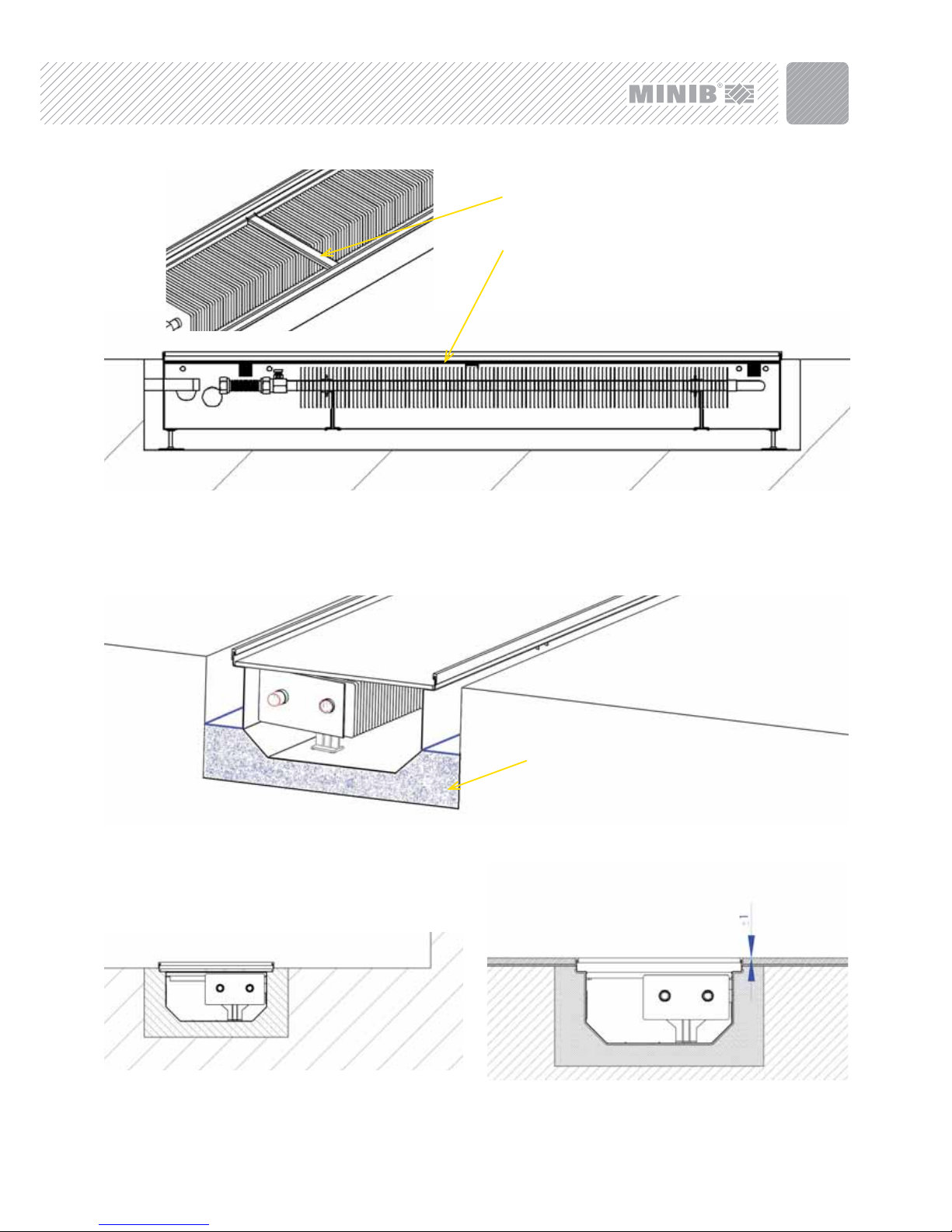
Figure 5: Hollow fl oor - brace for fl oor convector with fan .
Figure 6: Hollow fl oor - thermal insulation for fl oor convector with fan to
protect the fl oor on the exchanger side .
Figure 7: Hollow fl oor - anti-vibration foil for fl oor convector with fan. Its pur-
pose is to attenuate structure-borne noise and fan vibration. It is usually applied along the entire outer surface of the convector.
Figure 8: Solid fl oor - thermal insulation for fl oor convector with fan to protect
the fl oor on the exchanger side.
Figure 9: Solid fl oor - anti-vibration foil for fl oor convector with fan. Its
purpose is to attenuate structure-borne noise and fan vibration. It is usually
applied along the entire outer surface of the convector.
Figure 10: The drainage pipe can be located on a side of the convector other
than the side shown in the fi gure (depending on convector type).
Page 7

30
5. INSTALLATION
The heat exchanger must be connected to the distribution pipes
with the supplied stainless steel hoses.
A correctly installed convector is in a horizontal position and the
top edges of the casing are not damaged or bent in order to ensure
correct the functionality of the walk-on grille and the possibility of
heat exchanger deaeration.
A correctly installed convector has a decorative frame aligned
with the fi nal fl oor with a tolerance of ± 1mm.
It is recommended that the top convector cover (fi berboard) be
left in place during concreting to prevent the soiling of the convector interior. We would like to point out that walking on this convector cover is not permitted!
The convector must be fi xed in the fl oor with screw fi ttings or
another suitable material during concreting to prevent the vertical
movement of the convector after concrete pouring. A vertical load
may be applied to the convector during concreting.
Install necessary braces, thermal insulation, and/or vibration foil see paragraph 4.4.
installation manuals - fl oor convectors with fan
Figure 11: Insert 4 adjustment screws (6 screws for lengths over 2.5 m).
Figure 12: Place the convector in the installation hole and mark feet mounting
holes
Figure 13: Drill the holes (Ø6mm, depth 30-35 mm). Insert dowels in holes.
Figure 14: Clear perforated plugs of holes for heating water connection.
Figure 15: Level the convector in the installation hole and install heating water
pipes.
Page 8

31
floor convectors with fan - installation manuals
Figure 16: Attach the convector's fi xing feet into the dowels. Fix the feet with
quick-setting concrete.
Figure 18: Align the convector (with frame attached) using adjustment bolts. Set the fi nal height so that the convector frame is aligned with the fi nal fl oor
(± 1mm). Fix the feet with quick-setting concrete.
Figure 19: Connect the inlet and outlet pipes. See paragraph 6. Figure 20: MAX. PERMITTED exchanger tilt is approximately 60 degrees. See
paragraph 7. The exchanger can be moved in the heat exchanger so that the
ribs are not covered.
Figure 17: Install the power supply cable for the motors in the fi xed con-
vector. For safety reasons, check whether the power supply cable is not
energized.
Figure 21: Connect convector control unit. Use the connection
and control manual and observe the connection diagrams.
Page 9
32
installation manuals - fl oor convectors with fan
Figure 24: The entire space around the convector must be subsequently fi lled
with classical concrete up to the fi nal rough fl oor height. The convector is now
set in the rough fl oor, ready for fi nal fl oor installation (tiles, parquets, etc.).
Figure 25: A correctly installed convector has a decorative frame aligned with
the fi nal fl oor with a tolerance of ± 1mm.
Slurry – up to min. 1/3 of vat height
Figure 23: Pour concrete slurry or anhydride mixture to at least 1/3 of the convector height in order to minimize the noise. A convector with fan can vibrate if the
bottom is not properly concreted!
Figure 22: Make sure that all openings inside the vat are sealed so that the convector interior is not soiled during concreting! Install braces of the convec-
tor vat and wooden braces together with fi berboard cover.
Convector casing brace
Wooden braces + cover board
Page 10

33
6. CONNECTION OF FITTINGS
Connect the fi ttings with the supplied standard accessories (direct
connection from the convector face). Whenever you require connection from the window or room side, specify the connection method in your order. Accessories for a window or room side connection
are non-standard and comprise other fi ttings.
Connect individual inlet and outlet valves. The water inlet to the convector is provided with a ball valve (standard supply) enabling the
shut off of the heating water supply if necessary, or a thermostatic
valve (optional accessories) for fl ow control. The screw fi tting is installed on the outlet pipe. Sealing must be used in all joints.
Use the supplied fl exible stainless hoses for the exchanger connection (bellows hose), which will enable vertical exchanger tilting for
later cleaning. MAX. PERMITTED exchanger tilt is approximately 60
degrees. Connect the fi ttings according to Figure 22, 23, or 24.
Stainless hoses are designed to withstand a maximum pressure of
1.0 MPa. Hoses must not be stretched, compressed, or otherwise
deformed.
Media inlet: The media inlet pipe is always equipped with a ball valve
(standard supply) or a thermostatic valve (optional accessory). The
angle screw fi tting or angle thermostatic valve is connected to the
inlet in the case of connections from the window or room side.
Outlet (return pipe): The screw fi tting is always connected to the
return pipe. When thermostatic valves are used, observe the fl ow
direction of the valve and leave suffi cient space for the valve with
the given throughput. In some cases, it may be necessary to switch
the hot water inlet and outlet depending on the space required for
thermostatic head installation; however, fi ttings are always installed
as described above.
7. UNIT DEAERATION
Deaerate the unit by opening the deaerating valve during the fi rst use.
The deaerating valve is located near the water inlet on the heat exchanger fi tting.
8. OPTIONALES ACCESSORIES
Thermostatic valve - straight, ½”
Thermostatic valve - angular, ½”
Screw fi tting - straight, ½”
Screw fi tting - angular, ½”
Ball valve - straight, ½”
Ivar thermostatic head
Heimeier thermostatic head
Bellows hose ½” - ½” 65 mm
Bellows hose ½ - ½ 41 mm
Electro-thermal head 12V-NO
Accessories / angular connection comprise:
1x hose G1/2“ – 65 mm
1x bellows hose 41 mm
4x sealing KLIGERSIL C4400
2x angular screw fi tting
floor convectors with fan - installation manuals
Figure 27: Side heating water connection - from the window (non-standard
accessory - angular connection)
Figure 39: Deaerating valve.
Figure 26: Direct heating water connection (standard accessories).
Inlet - ball valve
Outlet - screw fi tting
Figure 28: Side heating water connection - in the room (non-standard ac-
cessory - angular connection).
Outlet screw fi tting angular
Inlet screw fi tting -
angular
Outlet screw fi tting angular
Inlet screw fi tting -
angular
Page 11

REGISTERED OFFICE OF THE COMPANY
MINIB,a.s.
Střešovická 465/49, 162 00 Prague 6
Czech Republic
Tel.: +420 220 180 780
Fax: +420 220 180 779
Email: export@minib.cz, www.minib.cz
MANUFACTURING
Manufacturing premises MINIB,a.s.
Býkev u Mělníka 84, 276 01 Býkev
Czech Republic
 Loading...