

Page 1

INSTALLATION GUIDE – WALL-MOUNTED DESIGN CONVECTOR GS
1. UNIT DESCRIPTION
Design wall-mounted GS convector with a face cover
panel. The glass panel can be removed from the convector body. The stainless steel body of the convector
is equipped with adjusting screws in the lower part of
the back side which are used to compensate for the
deflection from the wall.
3. TECHNICAL PARAMETERS
4. INSTALLATION AND FIXING OF THE UNIT
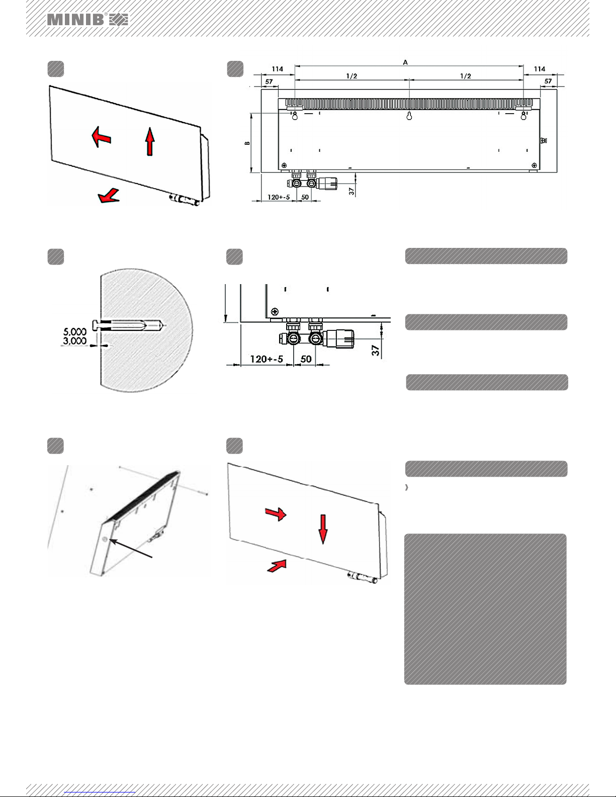
Table 1: Dimensions for drilling.
1 000 1 250
A B A B
GS 280 772 198 1 022 198
GS 360 772 288 1 022 288
GS 480 772 385 1 022 385
FIG. 1: GS CONVECTOR – REAR VIEW
1. CONVECTOR BODY – supporting member of the
convector parts (heat exchanger, valves and front
panel).
2. COVER PANEL – a design piece within the convector – GS glass.
3. AIR VENT VALVE – used for venting (bleeding) the
convector.
4. ANGLE VALVE DUO – a valve used for flow regulation.
5. THERMOSTATIC VALVE – used for manual regulation.
6. FIXING HOLES – for attaching the convector to the
wall.
GS design convectors are to be mounted on the wall or a partition wall with adequate load-bearing capacity with vertical positioning using the adjusting screws located in the
lower part of the back side of the convector body. The accessories include fixing screws for attachment. Standard dimensions of the GS convector: Height 280 mm, 360 mm
and 480 mm; length 1 000 mm and 1 250 mm.
Read the installation instructions before the installation. Attach the unit to the wall using the screws and
screw anchors from the accessories supplied. Hang
the unit using the holes cut out in the back side of the
stainless steel body of the convector.
Benefits of the GS design convector:
Possibility to choose your own design from the
MINIB catalogue
High output
Silent operation
Low hot water consumption
Minimum requirements for operation and mainte-
nance
Use: dry environment, according to the specifica-
tion.
Maximum operating pressure: 1 MPa.
Maximum operating temperature: 90 °C.
Operating medium: water. Water may not be mixed
with other substances, such as antifree¬ze fluids!
Environment: interiors with temperatures ranging
between +5 °C and +40 °C.
2. CONTENTS OF THE BOX
FIG. 2: Dimensions for drilling, rear view.
Page 2
1
2
3
Air vent valve
3
2
1
1.
3. 4.
5. 6.
2.
5. CONNECTION OF THE FITTINGS
6. VENTING THE UNIT
7. HANGING OF THE PANEL
8. OPTIONAL ACCESSORIES
WWW.MINIB.CZ
The convector is terminated with a female ½“ Euro
thread. In the GS convector it is used for connecting
the Duo angle valve. For additional options see the accessories table.
Vent (bleed) the unit using the air vent valve during the
first use as necessary. The air vent valve is always located on the side of the heat exchanger – see Figure 7.
For the sake of easier access we recommend hanging
the front panel after the unit has been vented. Install
the glass front panel back to the fixed convector body
with the connected heat exchanger. Fit the panel locks
in the locks on the convector body according to the
sequence of the arrows on Figure 8.
GS front panels: selection of panels and sizes
according to the MINIB catalogue
› For additional options see the catalogue or visit:
http://www.minib.com/
HEAD OFFICE:
MINIB,a.s., Střešovická 465/49, 162 00
Prague 6, Czech Republic
Tel.: +420 220 180 780, Fax: +420 220 180 779
Email: office@minib.cz, www.minib.cz
PRODUCTION
Manufacturing plant of MINIB, a. s
Býkev u Mělníka 84, 276 01 Býkev
Czech Republic
FIG. 3: By holding it by the edges remove the glass panel from
the convector body following the direction of the arrows
pictured.
FIG. 5: Install the 6 x 50 screws with anchors in the holes. Do
not tighten the screws.
FIG. 6: Measure the inlet and outlet of the heating line accor-
ding to Figure 2.
FIG. 7: Hang the unit, check whether it is installed horizontally,
and slightly tighten. Compensate the deflection, if any, from
the wall using the adjusting screws located in the lower
part of the unit, and finally tighten. Connect the valves to the
heating line. Fit the thermostatic valve.
FIG. 8: Place the glass panel onto the supporting member.
Follow the sequence of the arrows.
FIG. 4: Measure and mark the points for drilling the holes for the fixing screws according to the dimensions on Fig. 2 and Table1.
 Loading...