

Page 1

INSTALLATION INSTRUCTIONS
FOR CONTROLS
EB-A, EB-B AND EB-C
FOR CONVECTORS
w w w . m i n i b . c o m
Page 2

Introductory information
Minib controls are supplied from a standard 230V/50Hz supply network. To ensure electrical safety SELV low voltage at 12V AC
is used to supply the convectors via an isolating transformer. TT100, TT240 and TT300 are available according to the power re-
quirement. All electrical installation work must be undertaken by a qualied electrician.
The DC motors within the convectors are fed by the electronic board EB; this regulates the heat output by controlling the fan speed. The electronic board contains a microprocessor which is programmed for all three types of control EB-A, EB-B and EB-C. No
adjustments need to be made between the various control options as the controller automatically responds to the character of
the control signal and selects the appropriate type of regulation (note for control type EB-A a jumper must be tted to the electronic board).
The power supply from the transformer must be connected to terminals marked 12V AC in the convector. If a thermal switch is
used (supplied with all convectors) then the power supply is connected to terminals 12V AC and TK (see wiring diagram). The thermal switch is open when the water temperature is less than 35°C and the fans are stopped. For convectors also designed for cooling the contact closes when the cooling water temperature drops below 15°C.
The power supply should be connected directly to the 12V AC terminals in order to test the functionality of the unit and controls.
If the thermal switch is to be used then the wire should then be connected from terminal 12V DC to terminal TK (see control wiring diagrams).
The power supply to individual convectors can be made with cables with the relevant cross section and branching at each convector. Parallel (Y) connections can also be made between the transformer and the convectors and is more suitable for systems
with several concevtors. In each case the distance between the power supply (transformer) and the convector should not exceed
15m. Branching can be done in an electrical box in the wall or via the terminals directly under the cover of the convector.
CONTROL EB-A
Characteristic
EB-A is the simplest form of control and uses a potentiometer to continuously regulate the fan speed or switch the fans off.
The control is intended for regular areas which are occupied and the control can be adjusted by the occupants. Output is varied
by rotating the wall mounted hand potentiometer.
a/ The potentiometer in the frame ABB Tango
b/ The rotary thermostat in the frame ABB Tango.
(dimensions: 81x81 mm)
basic design in white colour, other color combinations must be ordered individually
a/ b/
Page 3
L
N
PE
L1�L2
EB* EB* EB*
rozváděč 230Vac
TT100�(TT240, TT300)
1�2�3�4�5�6
1�2�3�4�5�6
1�2�3�4�5�6
fan-coil
fan-coil
fan-coil
Základní zapojení regulace EB- A s možností plynulé manuální�regulace otáček ventilátorů.
Při�použití�termostatu se automaticky udržuje�nastavená�teplota.
Elektronický řídicí blok EB*�je�nastaven�na�plynulou regulaci otáček.
v místnosti
termostat
regulace�otáček
napájení�12Vac
řízení�otáček
CYKY J�3x�1,5�mm
2
CYKY O�3x�1,5�mm
2
potenciometr�-
nastavení�teploty
-
(do�15m)
Description of function:
In order to prepare the convectors for continuous speed control it is necessary to connect the jumper on the electronic board. Loosen the central screw which holds the board in place then push the board gently away from the convector so that there is access
for tting the jumper (do not disconnect any cable). Having tted the jumper the board is replaced with the screw into the original
position. Note. The power must be disconnected while tting the jumper.
The potentiometer is connected by three wires to the closest convector at the terminals marked 12V DC, 0V DC and Ur. Any multicore cable can be used that has multicoloured wires, for example 4 core communication cable with 4x0.19mm2 conductors and
the blue wire in 0V, the red wire in 12V and the third wire of another colour in Ur, the control voltage.
If automatic control of set temperature is required then a thermostat can be wired into the potentiometer which switches of the
fan when the set temperature is reached. If a thermostat is used then the jumper wire between terminals A and B in the potenti-
ometer must be removed and the terminals reconnected to the switching contacts of the thermostat (same wire specication as
between potentiometer and convector).
One potentiometer can control up to 10 convectors.
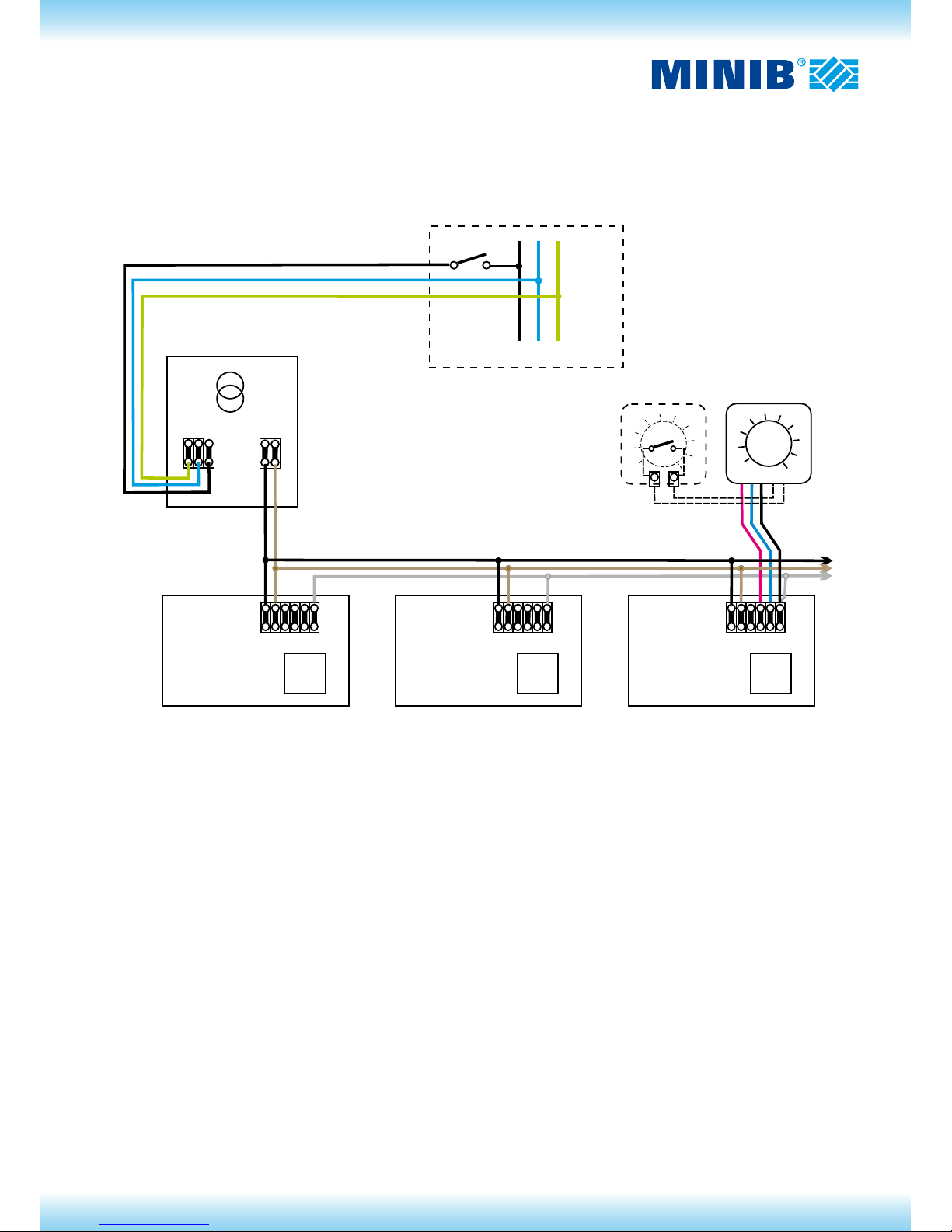
Scheme of control EB-A
The basic connection of the control EB-A with a possibility of the continuous fan speed control.
The set temperature is automatically maintained in the room when using the thermostat.
The electronic control block EB* is set on the continuous speed control.
Switchboard 230Vac
Thermostat
– temperature setting
Potentiometer
– speed control
Power supply 12Vac
Speed control
CYKY O 3x1.5 mm2 (up to 15m)
Page 4
EB
EBEB
EV
EB EB
1�2�3�4�5�6
1�2�3�4�5�6
1�2�3�4�5�6
1�2�3�4�5�6
1�2�3�4�5�6
fan-coil
fan-coil
Základní�zapojení��regulace�EB-B
TERMOSTAT
Fan-coil�s�elektroventilem�EV�použitým
pro�uzavření�průtoku�topné�vody. Činnost
EV�je�automaticky řízena�elektronikou�EB.
kontakt
termostatu
kontakt
termostatu
Fan-coil����tepelným�kontaktem,�který
elektronicky�zablokuje�otáčení�ventilá-
torů při�nízké�teplotě topné�vody.
napájení�12Vac
napájení�12Vac
L
N
PE
L1�L2
rozváděč 230Vac
TT100�(TT240, TT300)
CYKY J�3x�1,5�mm
2
fan-coil
fan-coil
fan-coil
napájení�12Vac
řízení�otáček
CYKY O��3x�1,5�mm
2
(do�15m)
CONTROL EB-B
Characteristics
Control EB-B automatically sets the fan speed based on the evaluation of the rate of switching of the thermostat. The controller
reacts to the opening and closing of the thermostat contacts to optimise the convector output and provide excellent dynamic control of the space temperature and minimise the noise levels of the fans.
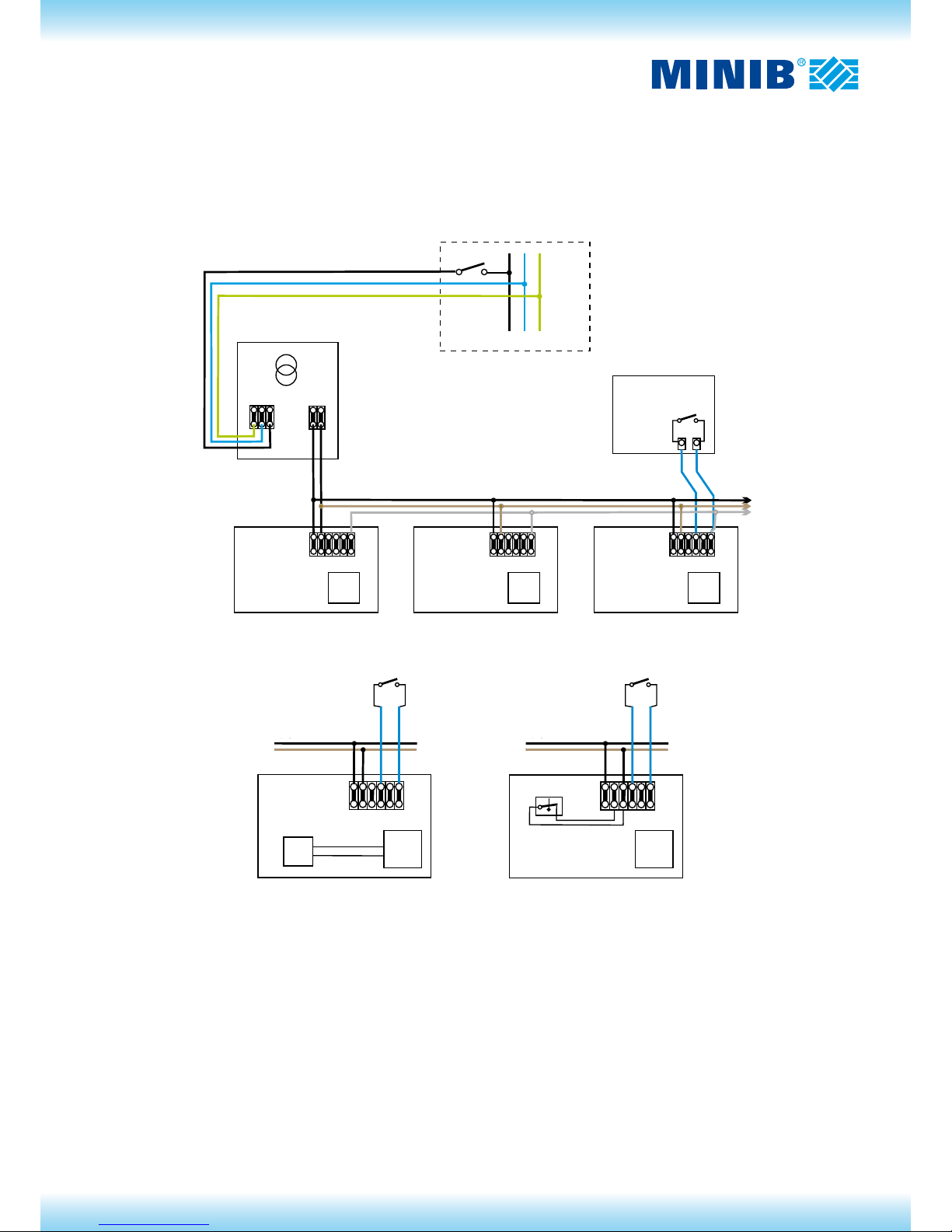
Scheme of control EB-B
Description of function:
The thermostat compares the required space temperature with the actual space temperature. When the space temperature is
above the required temperature the thermostat contacts are open and when it falls below the set temperature then the contacts
close. The is an hysteresis of around 1°C between the opening and closing temperatures which prevents rapid opening and clo-
sing of the contacts and inefcient control. This ensures that a minimum switching period of around 1 minute is maintained and
is particularly useful if the boiler is also controlled by thermostat.
The 12V DC signal from the thermostat is applied to terminal Ur on the electronic board in the convector. The electronic board
evaluates the switching period between on and off and sets the fan speed accordingly.
Any two core cable can be used for interconnection or the thermostat and the electronic board; communication cable or power
cable.
Switchboard 230Vac
Fan-coil with the electromagnetic valve EV used for closing the
heating water ow. The activity of EV is automatically controlled
by the EB electronic circuit.
Fan-coil with the electromagnetic valve and thermal contact,
which will disable the fan speed at lower temperature of he-
ating water.
Power supply 12Vac CYKY O 3x1.5 mm2 (up to 15m)
Thermostat
Speed control
Basic connection of the control EB-B
Thermostat
contact
Thermostat
contact
Power supply 12Vac Power supply 12Vac
Page 5
CONTROL EB-C
Characteristic
Control EB-C allows convectors to be operated in either automatic or manual mode. The control is design for use with thermostat
TH0482 which is adapted for a 12V DC supply taken from the electronic board within the convector.
In automatic mode control is similar to EB-B where the fan speed is set by the controller based upon the regularity of the opening and closing of the thermostat switching contacts. The highest available fan speed is set by the switch on the thermostat.
In manual mode the speed is set at low, medium or high and overrides the thermostat.
Description of function:
In automatic mode control EB-C compares the required space temperature with the actual space temperature. When the space
temperature is above the required temperature the thermostat contacts are open and when it falls below the set temperature
then the contacts close. The is an hysteresis of around 1°C between the opening and closing temperatures which prevents rapid
opening and closing of the contacts and inefcient control. This ensures that a minimum switching period of around 1 minute is
maintained and is particularly useful if the boiler is also controlled by thermostat.
A signal from the thermostat at a voltage level corresponding to low, medium or high speed as set on the thermostat is applied to
terminal Ur on the electronic board in the convector. The electronic board evaluates the periods of on/off switching and the voltage level to automatically set the fan speed.
In manual mode a voltage is applied from the thermostat to terminal Ur in the electronic board and the corresponding fan speed (low, medium, high) is set.
The potentiometer is connected by three wires to the closest convector at the terminals marked 12V DC, 0V DC and Ur. Any multicore cable can be used that has multicoloured wires, for example 4 core communication cable with 4x0.19mm2 conductors and
the blue wire in 0V, the red wire in 12V and the third wire of another colour in Ur, the control voltage.
EB EB EB
+12V
0�V
Ur
MINIB TH0482
1�2�3�4�5�6
1�2�3�4�5�6
1�2�3�4�5�6
1
2
3
4
5
6
L
N
PE
L1�L2
rozváděč 230Vac
TT100�(TT240, TT300)
CYKY J�3x�1,5�mm
2
fan-coil
fan-coil
fan-coil
napájení�12Vac
řízení�otáček
CYKY O��3x�1,5�mm (do�15m)
2
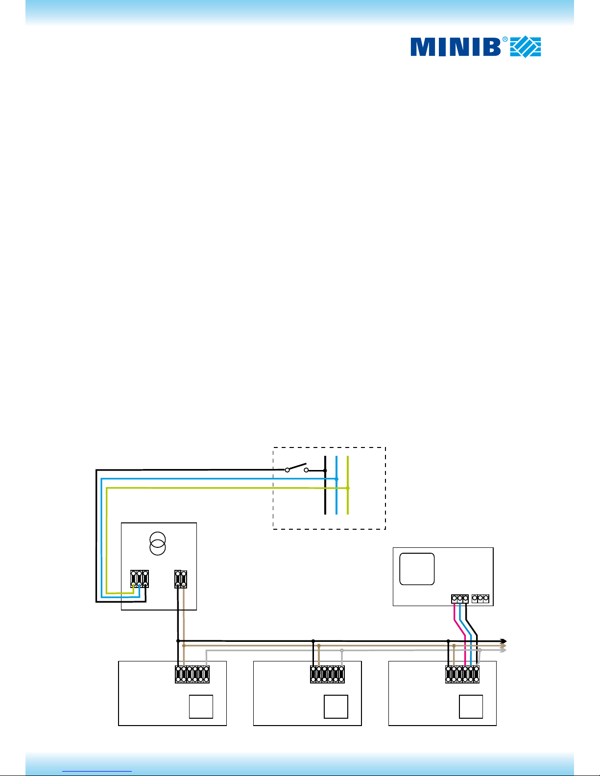
Scheme of control EB-C
Power supply 12Vac
CYKY O 3x1.5 mm2 (up to 15m)
Switchboard 230Vac
Thermostat
Speed control
Page 6
EB
1�2�3�4�5�6
fan-coil
Hi
Hi
Mid
Mid
Lo
Lo
Heat
Heat
Cool
Cool
Com
L
N
230Vac
kotel
L
N
ADA-EB
termostat
adaptér�230Vac
napájení�12Vac
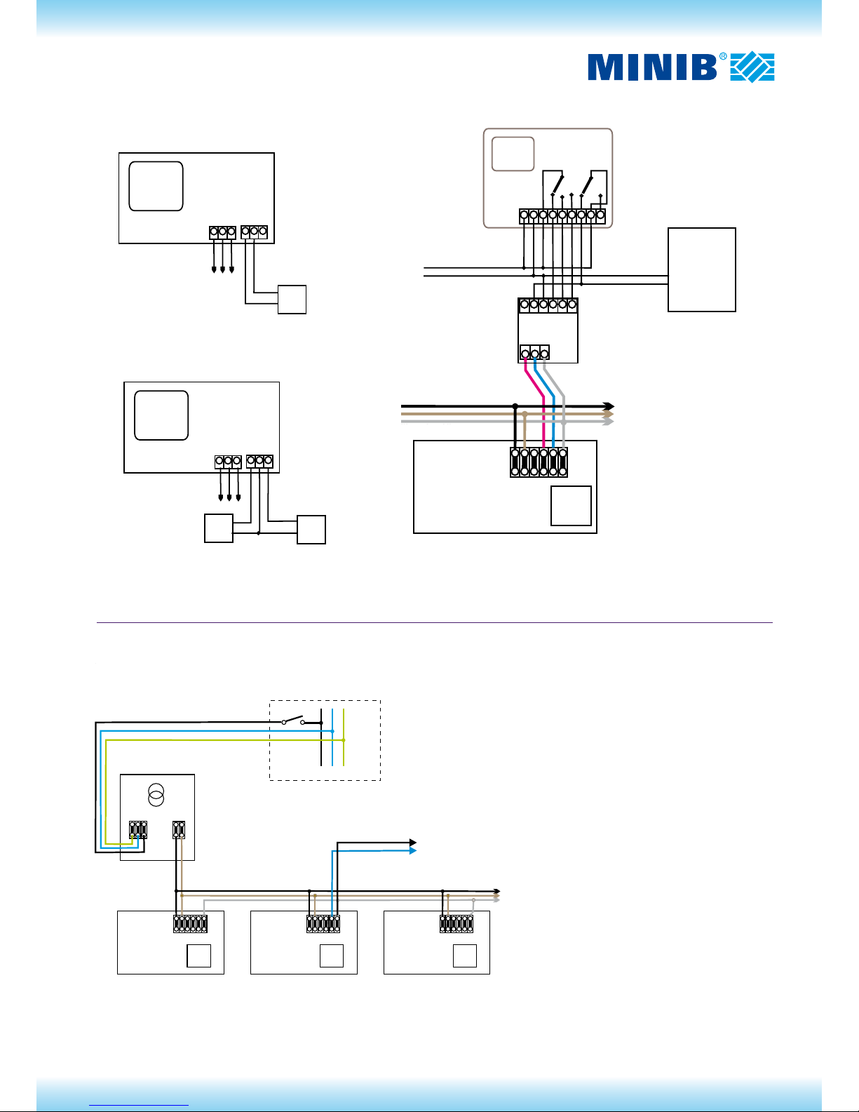
Přípojení řízení�fan-coil�jednotek�pomocí�adaptéru�na�termostat�s�napájením
230Vac�a�ovládáním�kotle.
otá kyč
topení
vypnuto
chlazení
řízení�otáček
napájení�a řízení
dalších�fan-coilů
s�napájením
230Vac
EB EB EB
+12V
+12V
+12V
0�V
0�V
0�V
Ur
Ur
Ur
MINIB TH0482
MINIB TH0482
MINIB TH0482
1�2�3�4�5�6
1�2�3�4�5�6
1�2�3�4�5�6
heat
heat
cool
cool
com
com
EV
EV
EV
elektroventil�12V�-�topná�voda
elektroventil�12V�-�topná�voda
elektroventil�12V�-�chladicí�voda
svorkovnice
fan-coilu
svorkovnice
fan-coilu
1
2
3
4
5
6
L
N
PE
L1�L2
rozváděč 230Vac
TT100�(TT240, TT300)
CYKY J�3x�1,5�mm
2
fan-coil
fan-coil
fan-coil
napájení�12Vac
řízení�otáček
CYKY O��3x�1,5�mm (do�15m)
2
+12V
+12V
0�V
0�V
Ur
Ur
MINIB TH0482
MINIB TH0482
1�2�3�4�5�6
heat
cool
com
EV
EV
elektroventil�12V�-�topná�voda
elektroventil�12V�-�chladicí�voda
svorkovnice
fan-coilu
1
2
3
4
5
6
rozváděč 230Vac
fan-coil
2
L
N
PE
L1�L2
EB* EB* EB*
rozváděč 230Vac
TT100�(TT240, TT300)
1�2�3�4�5�6
1�2�3�4�5�6
1�2�3�4�5�6
fan-coil
fan-coil
fan-coil
napájení�12Vac
řízení�otáček
CYKY J�3x�1,5�mm
2
CYKY O��3x�1,5�mm (do�15m)
2
O�V
řídicí�napětí�0�-�10�Vdc
připojení�k�centrálnímu řídicímu�systému
Schéma pro řízení nadřazeným systémem:
Power supply 12Vac CYKY O 3x1.5 mm2 (up to 15m)
Switchboard 230Vac
Speed control
Power supply 12Vac
Thermostat with the power
supply 230Vac
Speed
Heating
Off
cooling
Electromagnetic valve 12V – heating water
Fan-coil terminal board
Adaptor 230Vac
Power supply and control
of other fan-coils
Speed control
Connection of the control of fan-coil units through the adaptor to the thermostat with power
supply 230Vac and control of the boiler.
Electromagnetic valve 12V
Electromagnetic valve 12V
– heating water
Fan-coil terminal
board
Wiring diagram for the control by the superset system:
Connection to the central control
Control voltage 0 – 10Vac
0 V
Basic connection of the control EB with a possibility to control the fan speed through the central
systém with the output 0 to 10V. Fans are stopped in the range of the control voltage 0 to 3V; the
voltage between 3 to 10 V controls the fan speed in the range minimum – maximum.
The EB electronic control block* is set on the continuous speed control.
Page 7
Installation procedure
1. Installation of the heating system with convectors MINIB begins by placing of convectors to selected positions - see the
installation procedure convectors and by their connection to the heating system.
2. The isolating transformer and thermostat shall be placed to the selected place.
3. Apply the necessary connecting cables – see the wiring diagram. Branching of cables can be made either in boxes in the wall
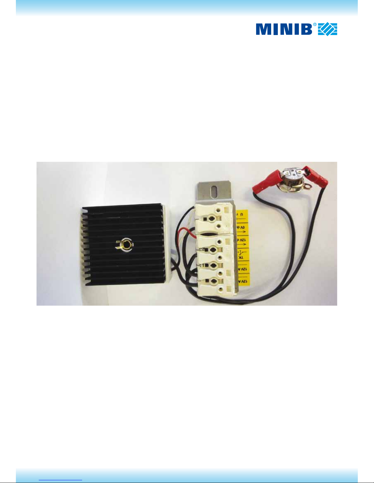
or directly on the terminal board in convectors. The terminal board for connection of power and control wires is placed on
either on the electronic block or on the main body of the convector. The wires must be connected to the proper positions on
the terminal board. Wrong connection may lead to the destruction of the electronic block and will not be accepted as the
reason for complaint. Therefore, pay a considerable attention to the correct connection. The picture shows the junction box
of the convector, including the connection of the temperature switch.
4. The temperature switch shall be connected according to the customer`s requirement.
5. Perform the electrical connection of all control components and convectors according to the selected wiring diagram.
Description of activation
1. If water in convectors is not hot enough and the thermal contact is used, it is possible to test the function of convectors after
switching power supply wire from the terminal TK to the terminal 12V AC. After the test, the wire shall be returned back to the
terminal TK.
2. The activation of the control shall be performed in the way that you switch on the circuit breaker in the main switchboard after
the connection check. The heating system will be put into operation.
3. You will set the heating mode on the thermostat and select temperature that is higher than the actual temperature in the
room. Depending on the thermostat type, the thermostat must switch on at the latest approx. in 1 minute. (This delay applies
only to electronic programmable thermostats, which prevents to fast repeated closing and opening of contacts and which
could lead to damage of some elements of heating systems.)
4. After switching the thermostat on all fans must start running in all convectors. Speed of all fans will become stable on the
same (set) speed within 1 minute.
5. Then set the temperature on the thermostat safely lower than the temperature in the room. The thermostat must switch off
approx. within 1 minute at the latest. Fans at controls EB-B and EB-C will further run but their speed will be gradually
decreasing. All fans must stop maximally after 20 minutes.
At the control EB-A, it is possible to test the speed setting, eventually to stop fans by turning the knob of the potentiometer.
When setting the speed, you must calculate with a certain time delay until stabilization of the corresponding speed. When
zero speed is set, the fans will stop immediately.
Page 8

w w w . m i n i b . c o m
 Loading...