

Page 1
INSTALLATION GUIDE – DP CONVECTORS
1. UNIT DESCRIPTION
An all-wood free-standing heater which uses the convection heating principle. Since the heater fully uses
physical laws of thermodynamics it represents one of
the most effi cient methods of interior heating.
Benefi ts of free-standing DP convectors:
High output
Silent operation
Low hot water consumption
Short response time
Design
Minimum requirements for operation and mainte-
nance
Contents of the box Position DP
Convector
All-wood casing 1 1
All-wood grille 2 1
Heat exchanger 3
1
Accessories
Ball valve - straight ½´´ 4 1
Screw fi tting - angular ½´´ 5 1
Contents of the box Position DP
Příslušenství
Hose G ½´´ - 41 mm 6 1
Hose G ½´´ - 65 mm 7 1
Gasket KLINGERSIL C4400 8 4
Screw anchor No. 10 *) 9 2-3
Wood screw 6 x 50 *) 10 2-3
DP template 11 1
3. TECHNICAL PARAMETERS
Use: dry environment.
Maximum operating pressure: 1 MPa.
Maximum operating temperature: 90 °C.
Operating medium: water. The use of other media
is prohibited. Water may not be mixed with other
substances, such as antifreeze fl uids!
Environment: interiors with temperatures ranging
between +5 °C and +40 °C.
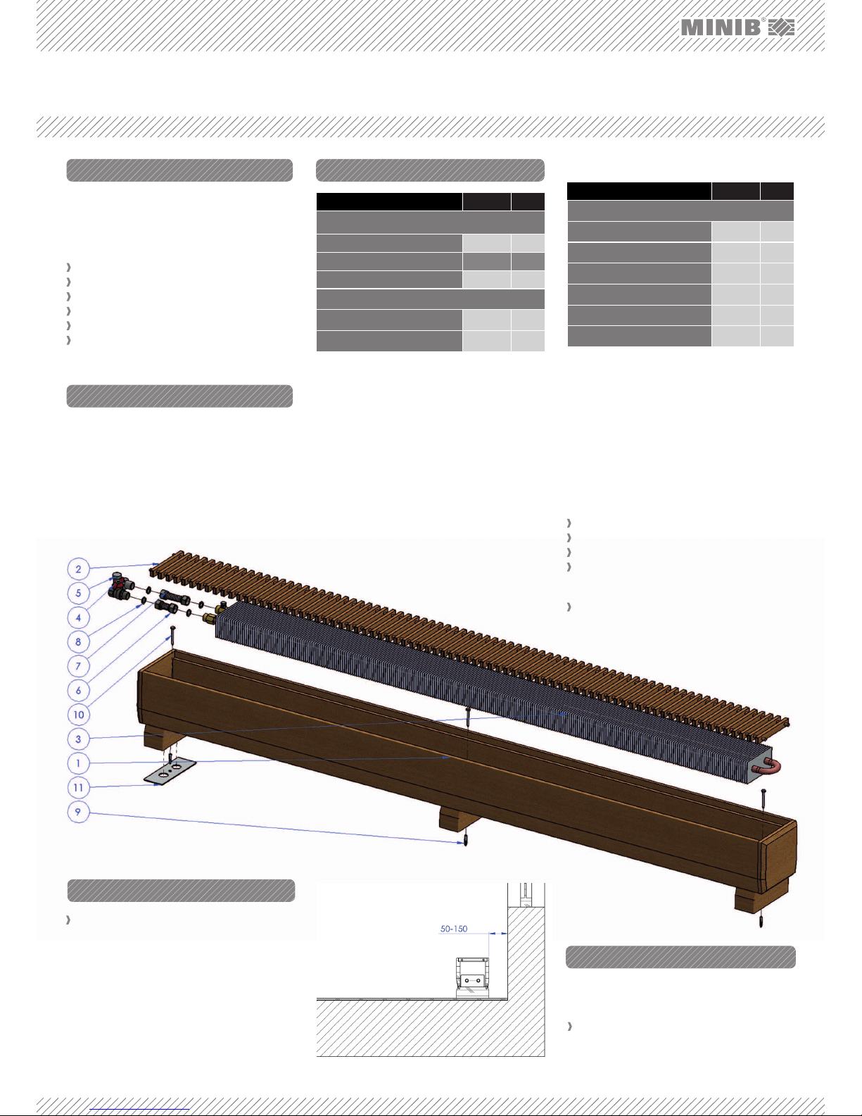
1.
WOODEN CONVECTOR CASING – the all-wood cas-
ing of the convector is a design piece and encases
the heat exchanger.
2. CONVECTOR GRILLE – a design piece protecting the
convector outlet. It must not be covered!!!
3. HEAT EXCHANGER – copper pipes with pressed-
Each position in the table corresponds to Figure No. 1
on aluminum fi ns through which the heating water
fl ows.
4. STRAIGHT BALL VALVE – used to shut off water
supply.
5. SCREW FITTING – a valve that controls/adjusts
heating water fl ow.
6. HOSE 41 mm
7. HOSE 65 mm – the bellows hose is a stainless hose
intended for fi tting the connection to the convector
exchanger.
8. GASKET – seals joints between valves, hoses, and
exchangers (KLINGERSIL C4400). MINIB, a.s. recommends this sealing as the optimal sealing solu-
*For lengths of 1 500 mm and 2 000 mm 3 pieces
4.1 Convector Position
The free-standing DP convector made by MINIB is
to be fl oor-mounted. Place the convector so that it
does not disturb the overall aesthetic experience of
the room. We recommend leaving a 50–150 mm space
between the convector and the wall - Figure 2. Never
cover the top grille - this would result in fl ow reduction
and a considerable decrease in the convector output
(Figure 2).
FIG. 1: COMPONENTS OF DP CONVECTOR:
tion because other materials (rubber, NBR, silicon)
do not provide the required sealing characteristics.
9. SCREW ANCHOR – for anchoring the screw.
10. SCREW – for fi xing the convector to the fl oor.
11. TEMPLATE – for marking the positions of the inlet
and return pipes and for marking the convector fi xing holes on the fl oor.
Select the correct convector position and location
– see paragraph 4.1.
Free-standing DP convectors are designed for installation right on the fl oor. Please read the following instructions before you start.
Plan the exact position before installation. The
convector unit (all-wood body) is to be used for
determination of the exact position.
2. CONTENTS OF THE BOX
4. BEFORE INSTALLATION
FIG. 2: Convector position
5. INSTALLATION
Page 2
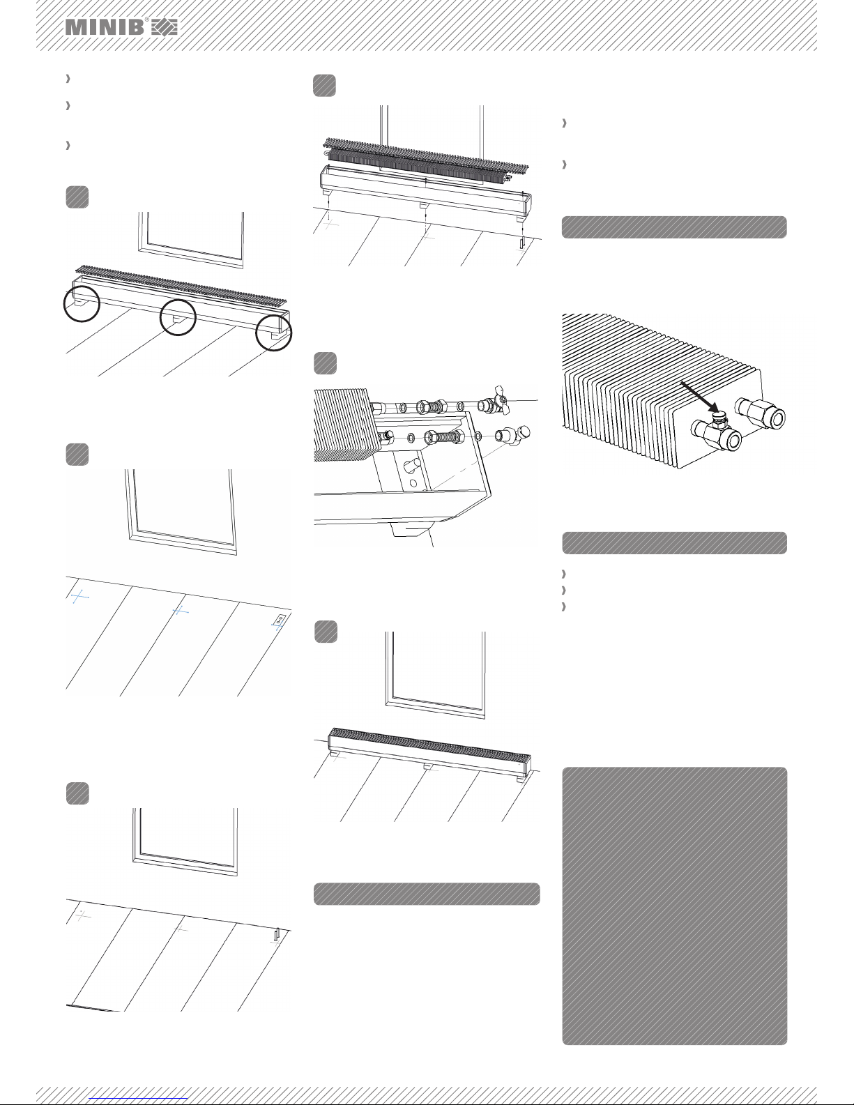
Vent (bleed) the unit using the air vent valve during the
fi rst use as necessary. The air vent valve is located
on the water outlet side on the heat exchanger fi tting
– see fi g. 9.
Fix the convector using the supplied mounting ac-
cessories.
The heat exchanger and the distribution pipes
must be connected using the supplied stainless
steel hoses.
A correctly installed convector is in horizontal po-
sition and fi rmly supported along its entire length
4.
1.
FIG. 5: Drill the holes for mounting of the convector body and
prepare the inlet and return pipes in the fl oor.
2.
3.
5.
6.
Connect the fi ttings using the supplied standard accessories.
Connect the individual inlet and outlet valves. The ball
valve (included in the standard supply) is connected
to the water inlet for shutting off the water supply if
necessary. The outlet pipe is equipped with a control
screw fi tting. Gaskets must be inserted in all connections. Use the supplied fl exible stainless steel hoses
(bellows hoses) to connect the heat exchanger. Connect the fi ttings as shown in Figure 7.
6. CONNECTION OF THE FITTINGS
The stainless hoses must not be extremely stretched,
stressed, or otherwise deformed.
Media inlet: The ball valve (included in the stand-
ard supply) is always connected to the water inlet.
Outlet (return pipe): The control valve is always
connected to the outlet pipe.
Thermostatic valve
Axial radiator valve ½´´
Electric valve EV 12 V
For additional options see the catalog or visit:
http://www.minib.com/
HEAD OFFICE:
MINIB, a.s.
Střešovická 465/49, 162 00 Prague 6
Czech Republic
Tel.: +420 220 180 780
Fax: +420 220 180 779
E-Mail: offi ce@minib.cz, www.minib.cz
PRODUCTION
Manufacturing plant of MINIB, a. s.
Býkev u Mělníka 84, 276 01 Býkev
Czech Republic
8. OPTIONAL ACCESSORIES
WWW.MINIB.CZ
7. VENTING THE UNIT
FIG. 8: Replace the grille.
FIG. 3: Place the convector in the required position. Mark the
position of the DP convector body legs.
FIG. 4: Use the template to mark the inlet pipe, return pipe, and
fi xing screw positions. For pipe installation, use either the
right or left leg of the DP convector; never use the middle leg
FIG. 6: Insert screw anchors in the prepared holes. Remove
the grille and the convector exchanger. Fit the convector body on the pipes and the screw anchors. Screw the
convector body to the fl oor
FIG. 9: Air vent valve
FIG. 7: Install the heat exchanger and connect the fi ttings.
Check tightness of the connections.
 Loading...