

miniature aircraft XCell Stratus, X-Cell Stratus 126-100 Assembly Manual


Assembly Manual for XCell Stratus Kits #1026
Table Of Contents
REVISIONS TO THIS MANUAL.........................................................................................................................................................3
ERRATA ..................................................................................................................................................................................................3
KIT INTRODUCTION...........................................................................................................................................................................4
R/C HELICOPTER SAFETY.......................................................................................................................................................................4
GUIDELINES FOR SAFE R/C HELICOPTER FLIGHT ...................................................................................................................................4
X-CELL LIMITED WARRANTY...............................................................................................................................................................5
WARRANTY PROCEDURES ......................................................................................................................................................................5
X-CELL STRATUS WARRANTY REGISTRATION.......................................................................................................................................5
KIT ASSEMBLY.....................................................................................................................................................................................6
Supplies Needed for Assembly ...........................................................................................................................................................6
Adhesives Needed...............................................................................................................................................................................6
Tools Needed for Assembly................................................................................................................................................................7
Assembly Tips ....................................................................................................................................................................................7
UNBAGGED PARTS..................................................................................................................................................................................8
Kit Box ...............................................................................................................................................................................................8
LOWER FRAME ASSEMBLY...................................................................................................................................................................10
Bag 1 – Bottom Plate Components..................................................................................................................................................10
Bag 2 – Engine Specific Components ..............................................................................................................................................17
UPPER FRAME ASSEMBLY ....................................................................................................................................................................40
Bag 3 – Left Upper Frame Components..........................................................................................................................................40
Bag 4 – Right Upper Frame Components........................................................................................................................................73
UPPER/LOWER FRAME ASSEMBLY .......................................................................................................................................................93
CONTROL SYSTEM ASSEMBLY..............................................................................................................................................................97
Bag 5 – Upper Control System Components....................................................................................................................................97
Bag 6 – Lower Control System/Canopy Components....................................................................................................................106
CANOPY ASSEMBLY ...........................................................................................................................................................................121
ROTOR HEAD ASSEMBLY ...................................................................................................................................................................127
Bag 7 – Rotor Head Components...................................................................................................................................................127
TAIL ROTOR ASSEMBLY .....................................................................................................................................................................149
Bag 8 – Tail Rotor Components.....................................................................................................................................................149
TAIL BOOM ASSEMBLY ......................................................................................................................................................................160
Bag 9 – Tail Boom Components.....................................................................................................................................................160
Bag 10 – Tail Rotor Components...................................................................................................................................................162
FINAL ASSEMBLY ...............................................................................................................................................................................178
ROTOR BLADES................................................................................................................................................................................178
SETUP INSTRUCTIONS...................................................................................................................................................................179
FINAL INSPECTION.........................................................................................................................................................................181
PRE-FLIGHT INSTRUCTIONS.......................................................................................................................................................181
INITIAL TRIMMING INSTRUCTIONS.........................................................................................................................................182
MAINTENANCE ITEMS...................................................................................................................................................................183
CANOPY CUT-OUT TEMPLATE – NO MUFFLER.....................................................................................................................185
CANOPY CUT-OUT TEMPLATE – WITH HATORI SB16/SB17................................................................................................186
Created: 11/1/2005 Copyright Miniature Aircraft USA Page 2 Of 188
This document may not be distributed without permission of Miniature Aircraft USA

Assembly Manual for XCell Stratus Kits #1026
Revisions to this Manual
• 10/01/05 – Version 1.2 - Revisions for final kitting modifications
• 10/08/05 – Version 1.3 – Added Canopy Cut-Out Template
• 11/01/05 - Version 1.3 – Added Canopy Cut-Out with Muffler
For the most current version of this manual, please refer to
www.miniatureaircraftusa.com, visit the Stratus helicopter kit and download the
assembly manual
Errata
None Noted
Created: 11/1/2005 Copyright Miniature Aircraft USA Page 3 Of 188
This document may not be distributed without permission of Miniature Aircraft USA

Assembly Manual for XCell Stratus Kits #1026
Kit Introduction
R/C Helicopter Safety
A radio controlled model helicopter is a technically complex device that must be built and operated with
care. It is also a fascinating and challenging part of the R/C sport, the mastery of which is very rewarding.
A model helicopter must be built exactly in accordance with the building instructions. The kit manufacturer
has spent much time and effort refining his product to make it reliable in operation and easy to build. The
essentially bolt together construction can proceed quite rapidly, giving the builder a strong sense of
accomplishment that encourages hasty progress from one construction phase to the next, so that the
completed model can be more quickly seen and enjoyed. It is essential to recognize and guard against this
tendency. Follow building instructions exactly. Vibration an d stress levels are high and all fasteners and
attachments must be secure for safe operation.
Note that this is the first use of the word SAFETY in these comments. Previously the kit manufacturer’s
efforts to ensure reliable operation were mentioned. That is ALL that he can do. Safe operation is the
responsibility of the builder/flyer and starts with careful construction and continues with selection and
installation of reliable radio equipment and engine.
The need for safety is nowhere greater than at the flying field. A number of guidelines for safe flight have
been developed by experienced flyers and are set down here. It is urged that they be read, understood
and followed.
Guidelines for Safe R/C Helicopter Flight
• Fly only at approved flying fields and obey field regulations.
• Follow frequency control procedures. Interference can be dangerous to all.
• Know your radio. Check all transmitter functions before each flight.
• Be aware that rotating blades are very dangerous and can cause serious injury.
• Never fly near or above spectators or other modelers.
• If a beginner, get help trimming the model first and flight training later.
• Don’t “track” the main blades by holding the tail boom. This is a temptation to builders who cannot
hover yet and is very dangerous.
• Follow all recommended maintenance procedures for model, radio and engine.
WARNING!
This helicopter is not a toy, but a complex flying machine that must be assembled with care by a
responsible individual. Failure to exert care in assembly, or radio or accessory installation, may result in a
model incapable of safe flight or ground operation. Rotating components are an ever present danger and
source of injury to operators and spectators. Since the manufacturer and his agents have no control over
the proper assembly and operation of his products, no responsibility or liability can be assumed for their
use.
Created: 11/1/2005 Copyright Miniature Aircraft USA Page 4 Of 188
This document may not be distributed without permission of Miniature Aircraft USA

Assembly Manual for XCell Stratus Kits #1026
X-CELL Limited Warranty
The warranty covers defects in material or workmanship or missing components to the original purchaser
for 30 days from the date of purchase. Miniature Aircraft, USA will replace or repair, at our discretion, the
defective or missing component. Defective components must be returned to us prior to replacement.
Any part, which has been improperly installed, abused, crash damaged or altered by unauthorized
agencies, is not covered. Under no circumstances will the buyer be entitled to consequential or incidental
damages. The components used in this kit are made form special materials designed for special
applications and design strengths. We recommend that all replacement parts be original parts
manufactured by Miniature Aircraft, USA, to ensure proper and safe operation of your model. Any part
used which was manufactured by any firm other than Miniature Aircraft, USA, VOIDS all warrantees of this
product by Miniature Aircraft, USA.
Warranty Procedures
Mail all warranty information within 15 days of original purch a se date. If service is required, send the
component in question (if not missing) together with a photocopy of your bill of sale and an accurate
description of the problem and part. Ship components fully insured and prepaid. Miniature Aircraft, USA is
not responsible for any shipping damages. We will, at our discretion, notify you of any costs involved, or
ship it COD. You are required to pay all postage, shipping and insurance charges.
X-Cell Stratus Warranty Registration
Please print or type, filling in the information listed below and mail immediately
Model No:____________ Serial No:____________ Price paid:___________________
Owners name:______________________________ Age_______________________
Address:____________________ ________________ Phone:_____________ ______
City:_______________________ State:____________ Zip:___________________
Purchased from: ________________________________________________________
Dealer’s address ________________________________________________________
Comments: __________________________ __________________________ ________
______________________________________________________________________
_________________________________________________________________________
MINIATURE AIRCRAFT USA
31713 Long Acres Drive
Sorrento, FL 32776
Phone (352) 383-3201
FAX (352) 383-3204
Created: 11/1/2005 Copyright Miniature Aircraft USA Page 5 Of 188
This document may not be distributed without permission of Miniature Aircraft USA

Assembly Manual for XCell Stratus Kits #1026
Kit Assembly
In order to assemble this kit, you will need a number of additional supplies and tools to ensure the best
final result. They are as follows:
Supplies Needed for Assembly
Blue Thread
Lock
Red Thread
Lock
Green
Thread Lock
Adhesives Needed
Slow
Cyanoacrylate
JB Weld
Oil Grease
Created: 11/1/2005 Copyright Miniature Aircraft USA Page 6 Of 188
This document may not be distributed without permission of Miniature Aircraft USA

Assembly Manual for XCell Stratus Kits #1026
Tools Needed for Assembly
M5 Nut Driver
M5.5 Nut Driver
M7 Nut Driver
M4 Nut Driver
1.5mm allen driver
2.0mm allen driver
2.5mm allen driver
3.0mm allen driver
Needle Nose Pliers
Phillips Screwdriver #1
Flat Screwdriver 2.5mm
Razor Knife (Xacto)
8.0mm wrench
5.5mm wrench
4.0mm wrench
Assembly Tips
• Follow the instructions. The methods of construction documented in this manual have been proven
to work.
• Follow the order of assembly. The instructions have been organized into major sections and have
been written in such a way that each step builds upon the work done in the previous step.
Changing the order of assembly may result in unnecessary steps
• The photos in this manual are organized within each stop to correspond with the order of assembly.
The sequence of the photos within a step, is from top to bottom and from left to right.
• Clean all metal parts: All of the steel parts in this kit are coated with a lubricant to prevent them
from rusting. This coating can interfere with the adhesives and thread locks needed for assembly.
Use a solvent such as alcohol or acetone to clean the various metal parts, especially threads
• Use thread lock as indicated. Model helicopters are subject to vibration and failing to use thread
lock on any non-locking assembly may result in a part becoming loose or falling off
Created: 11/1/2005 Copyright Miniature Aircraft USA Page 7 Of 188
This document may not be distributed without permission of Miniature Aircraft USA

Assembly Manual for XCell Stratus Kits #1026
Unbagged Parts
This section documents the parts found in the kit box which are not common to other bags
Kit Box
Kit Box Contents
Created: 11/1/2005 Copyright Miniature Aircraft USA Page 8 Of 188
This document may not be distributed without permission of Miniature Aircraft USA
Assembly Manual for XCell Stratus Kits #1026
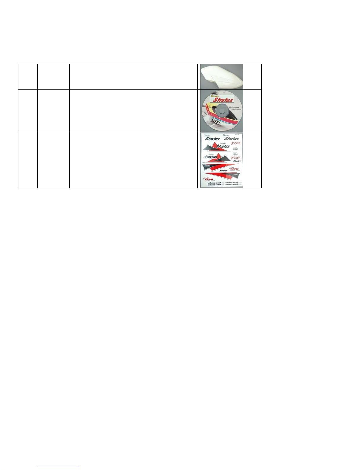
Box parts list
1 122-90 Canopy
1 126-100 Assembly Instructions – CD-ROM
1 126-85 Decal Set
Created: 11/1/2005 Copyright Miniature Aircraft USA Page 9 Of 188
This document may not be distributed without permission of Miniature Aircraft USA
Assembly Manual for XCell Stratus Kits #1026
Lower Frame Assembly
This section describes the assembly of the lower frame assembly
Bag 1 – Bottom Plate Components
Bag 1
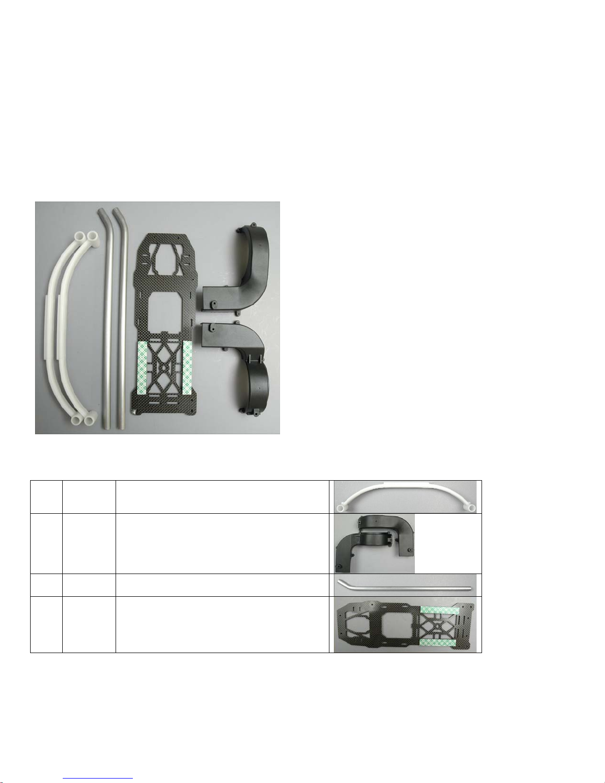
Bag 1A parts list
2 0151 Struts
1 0548-5 Fan Shroud (right & left)
2 122-39 Skids
1 126-20 Carbon Main Base Plate
Created: 11/1/2005 Copyright Miniature Aircraft USA Page 10 Of 188
This document may not be distributed without permission of Miniature Aircraft USA
Assembly Manual for XCell Stratus Kits #1026
Bag 1B
Bag 1C
Created: 11/1/2005 Copyright Miniature Aircraft USA Page 11 Of 188
This document may not be distributed without permission of Miniature Aircraft USA

Assembly Manual for XCell Stratus Kits #1026
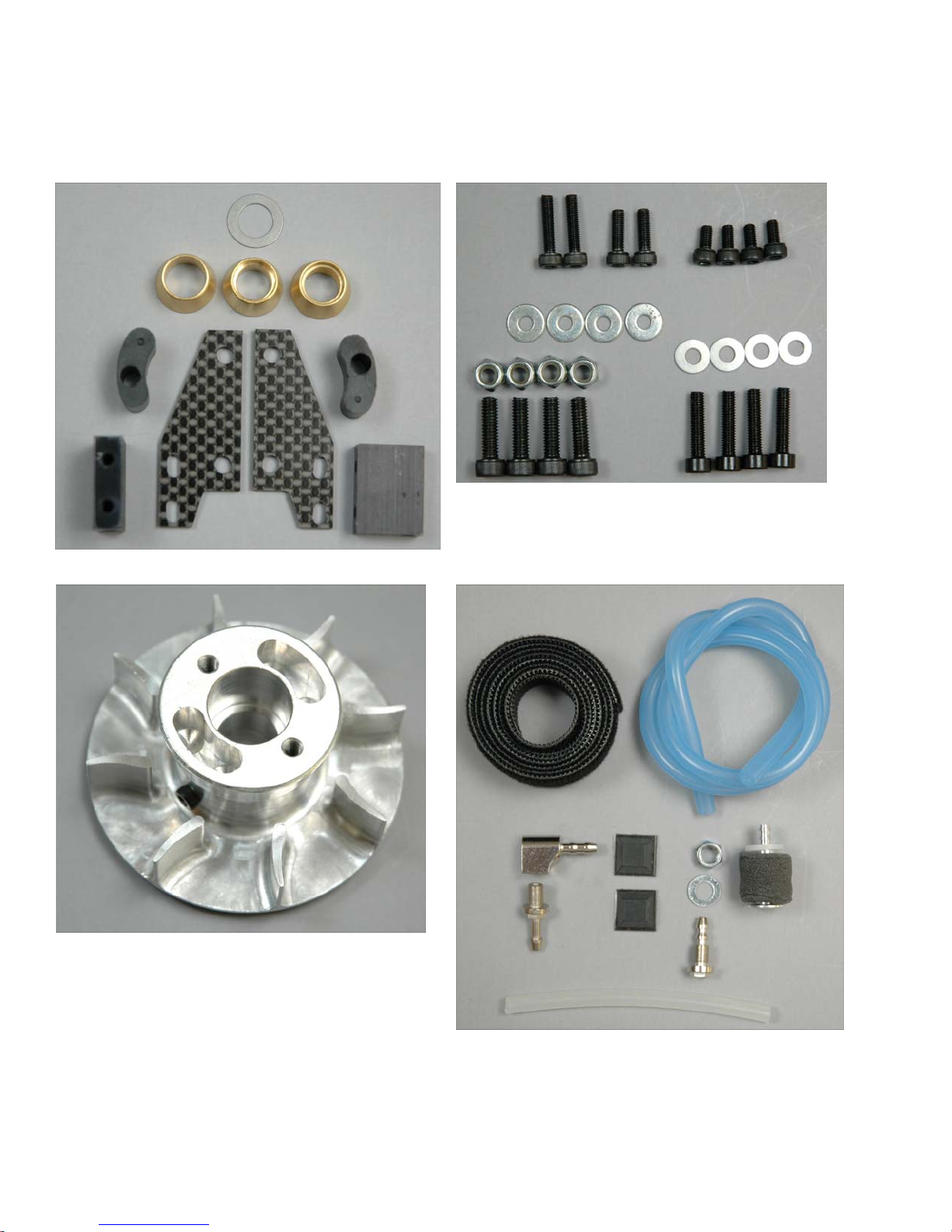
Bag 1B parts list
4 0008 M3.5 washer
4 0009 M3 Washer – large
4 0021 M4 Locknut
4 0060-1 M3 x 6 Socket Head bolt
2 0063 M3 x 10 Socket Head bolt
2 0067 M3 x 14 Socket Head bolt
4 0068 M3.5 x 15 Socket Head bolt
4 0080 M4 x 14 Socket Head bolt
1 0331 Shim Washer M13x.50
1 0546-11 Y.S. Upper Collet
2 0546-16 Clutch Dampers
Created: 11/1/2005 Copyright Miniature Aircraft USA Page 12 Of 188
This document may not be distributed without permission of Miniature Aircraft USA
Assembly Manual for XCell Stratus Kits #1026
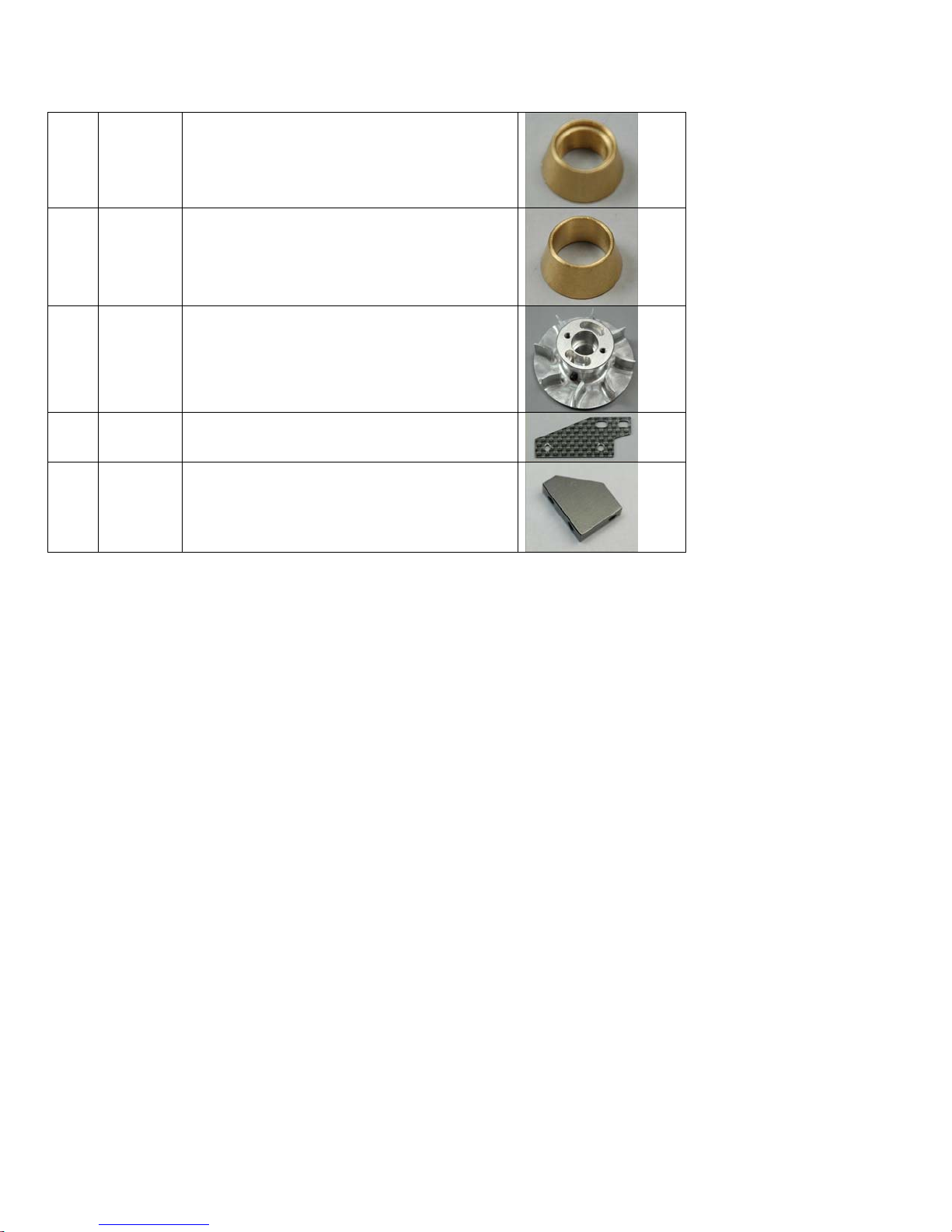
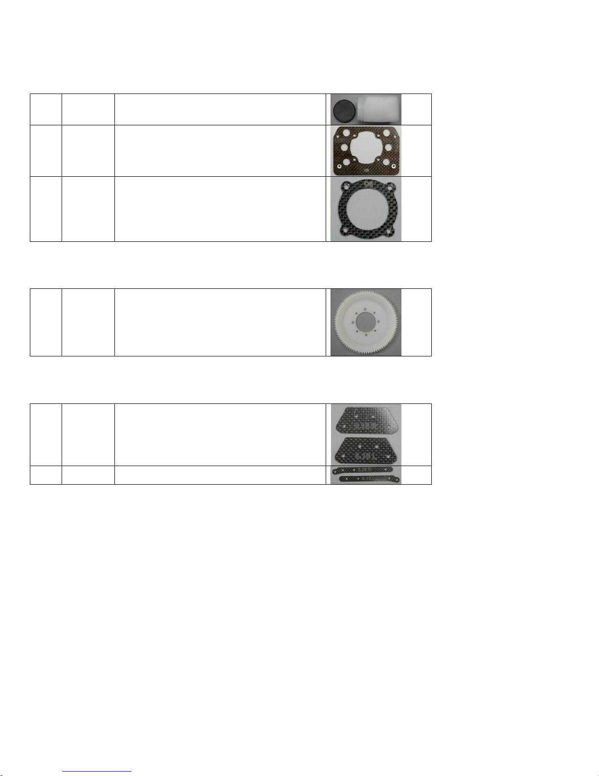
1 0546-5 O.S. Upper Collet
1 0546-6 Brass Base Collet
1 0579-4 Fan Unit
2 126-23 Carbon Motor Side Mounts
2 126-86 Rectangular Blocks
Created: 11/1/2005 Copyright Miniature Aircraft USA Page 13 Of 188
This document may not be distributed without permission of Miniature Aircraft USA
Assembly Manual for XCell Stratus Kits #1026
Bag 1C parts list
1 0011 M5 Washer
1 0013 M5 Hex nut
1 0397 Fuel Line – 18” – outside of tank
1 0405 Fuel Vent
1 0408 Fuel Fitting nipple
1 0409 90° Fuel Fitting
1 115-30 5/8” Velcro – 28.5” length
1 115-65 Fuel Line – 3” – inside of tank
2 126-27 Rubber Tank Bump-ons
1 4295 Fuel Magnet
Created: 11/1/2005 Copyright Miniature Aircraft USA Page 14 Of 188
This document may not be distributed without permission of Miniature Aircraft USA

Assembly Manual for XCell Stratus Kits #1026
Bag 1D
Bag 1D content
4 0009 M3 Washer – small
4 0019 M3 Locknuts
5 0029 M2.2 x 9.5 Phillips screw
4 0058-1 M4 x 6 Socket Set Screws
6 0060-1 M3 x 6 Socket head bolt
Created: 11/1/2005 Copyright Miniature Aircraft USA Page 15 Of 188
This document may not be distributed without permission of Miniature Aircraft USA
Assembly Manual for XCell Stratus Kits #1026
4 0063 M3 x 10 Socket head bolt
4 0065 M3 x 12 Socket head bolt
4 0073 M3 x 20 Socket Head bolt
2 0586-16 Corner Blocks
2 126-26 “A” Frame Supports
2 126-73 Lower Graphite Shroud Brackets
Created: 11/1/2005 Copyright Miniature Aircraft USA Page 16 Of 188
This document may not be distributed without permission of Miniature Aircraft USA

Assembly Manual for XCell Stratus Kits #1026
Bag 2 – Engine Specific Components
Bag 2 - YS
Bag 2A
Bag 2B
Bag 2C
Created: 11/1/2005 Copyright Miniature Aircraft USA Page 17 Of 188
This document may not be distributed without permission of Miniature Aircraft USA
Assembly Manual for XCell Stratus Kits #1026
Bag 2A - YS parts list
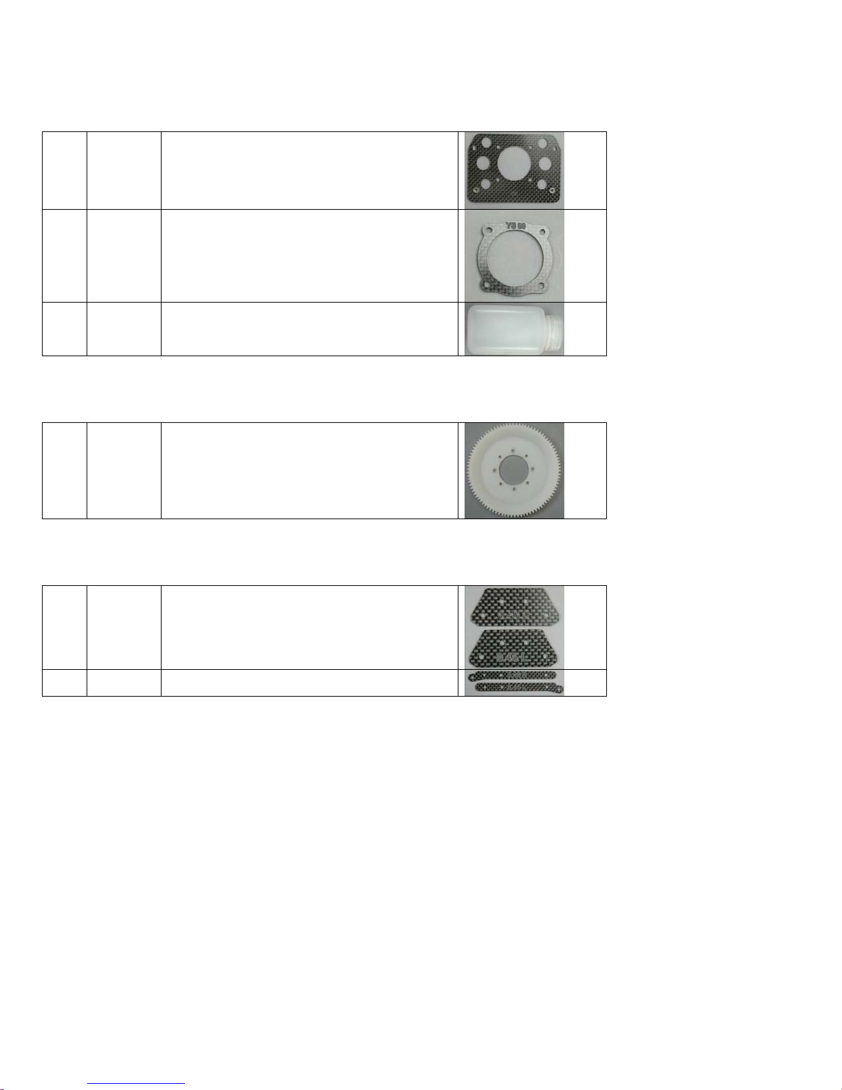
1 126-28 Main Motor Base Plate – YS
1 126-29 Adapter Plate – YS
1 126-52 Pressurized Fuel Tank
Bag 2B – YS parts list
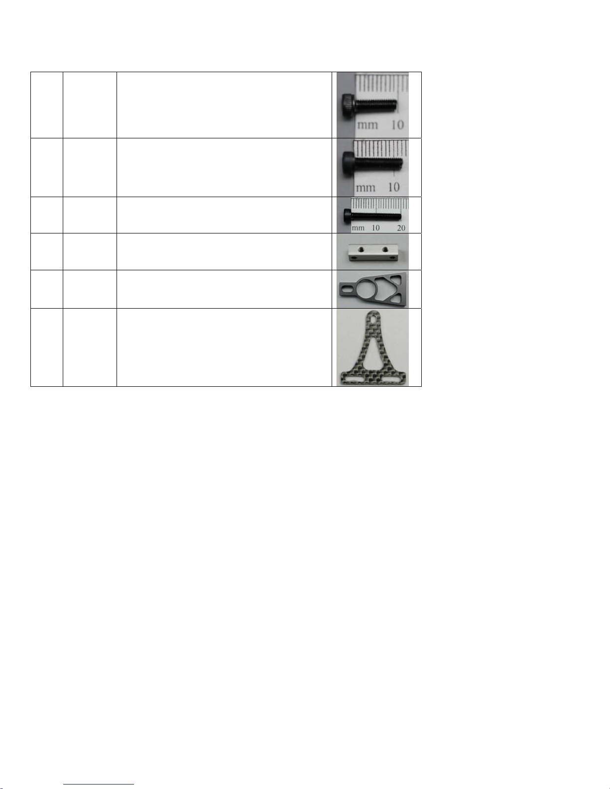
1 0865-93 93 tooth main drive gear
Bag 2C - YS parts list
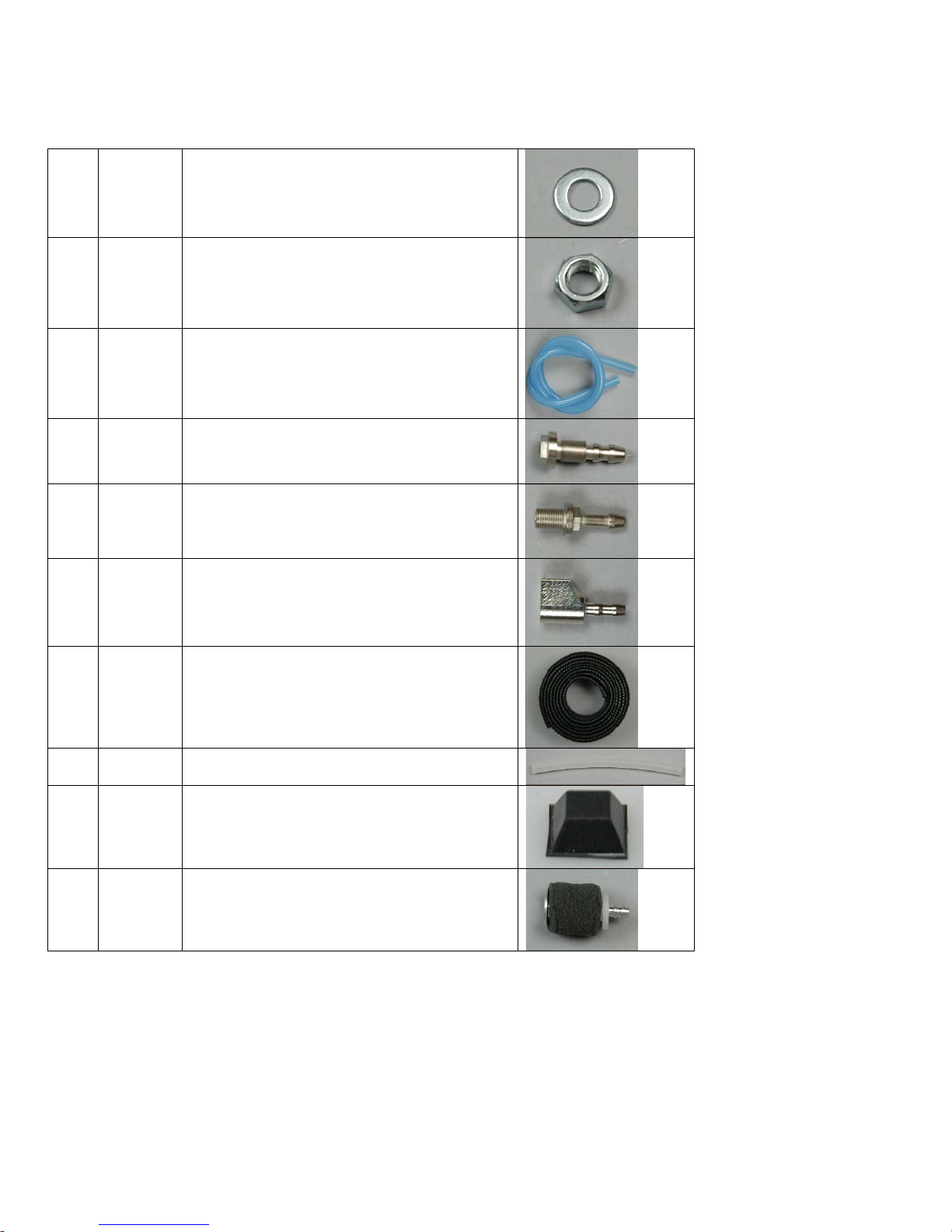
2 126-44 8.45 upper clutch plates (Right & left)
2 126-45 8.45 lower clutch plates (Right & left)
Created: 11/1/2005 Copyright Miniature Aircraft USA Page 18 Of 188
This document may not be distributed without permission of Miniature Aircraft USA
Bag 2 - OS
Bag 2A
Assembly Manual for XCell Stratus Kits #1026
Bag 2B
Bag 2C
Created: 11/1/2005 Copyright Miniature Aircraft USA Page 19 Of 188
This document may not be distributed without permission of Miniature Aircraft USA
Assembly Manual for XCell Stratus Kits #1026
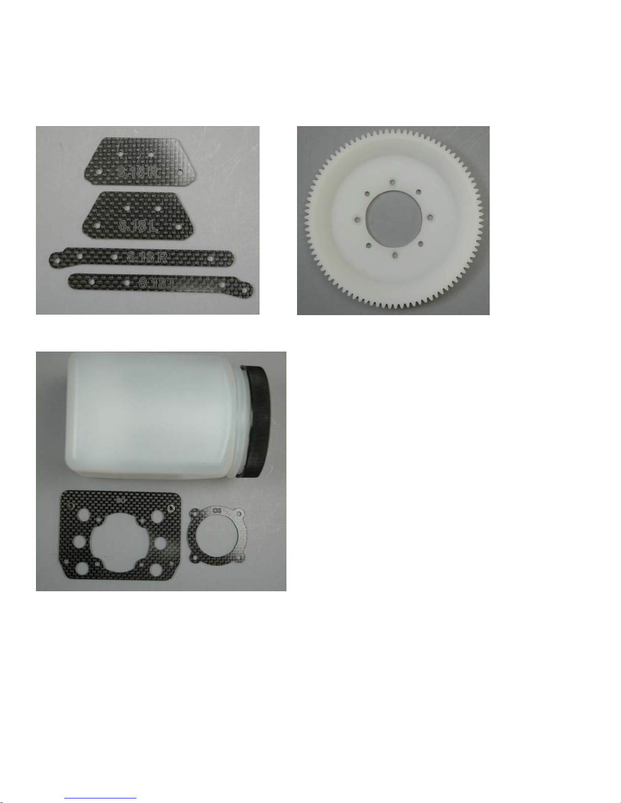
Bag 2A - OS parts list
1 126-21 Non-Pressurized Fuel Tank
1 126-24 Main Motor Base Plate – OS
1 126-25 Adapter Plate – OS
Bag 2B – OS parts list
1 0865-90 90 tooth main drive gear
Bag 2C - OS parts list
2 126-40 8.18 upper clutch plates (Right & left)
2 126-41 8.18 lower clutch plates (Right & left)
Created: 11/1/2005 Copyright Miniature Aircraft USA Page 20 Of 188
This document may not be distributed without permission of Miniature Aircraft USA
Assembly Manual for XCell Stratus Kits #1026
Assembly Steps
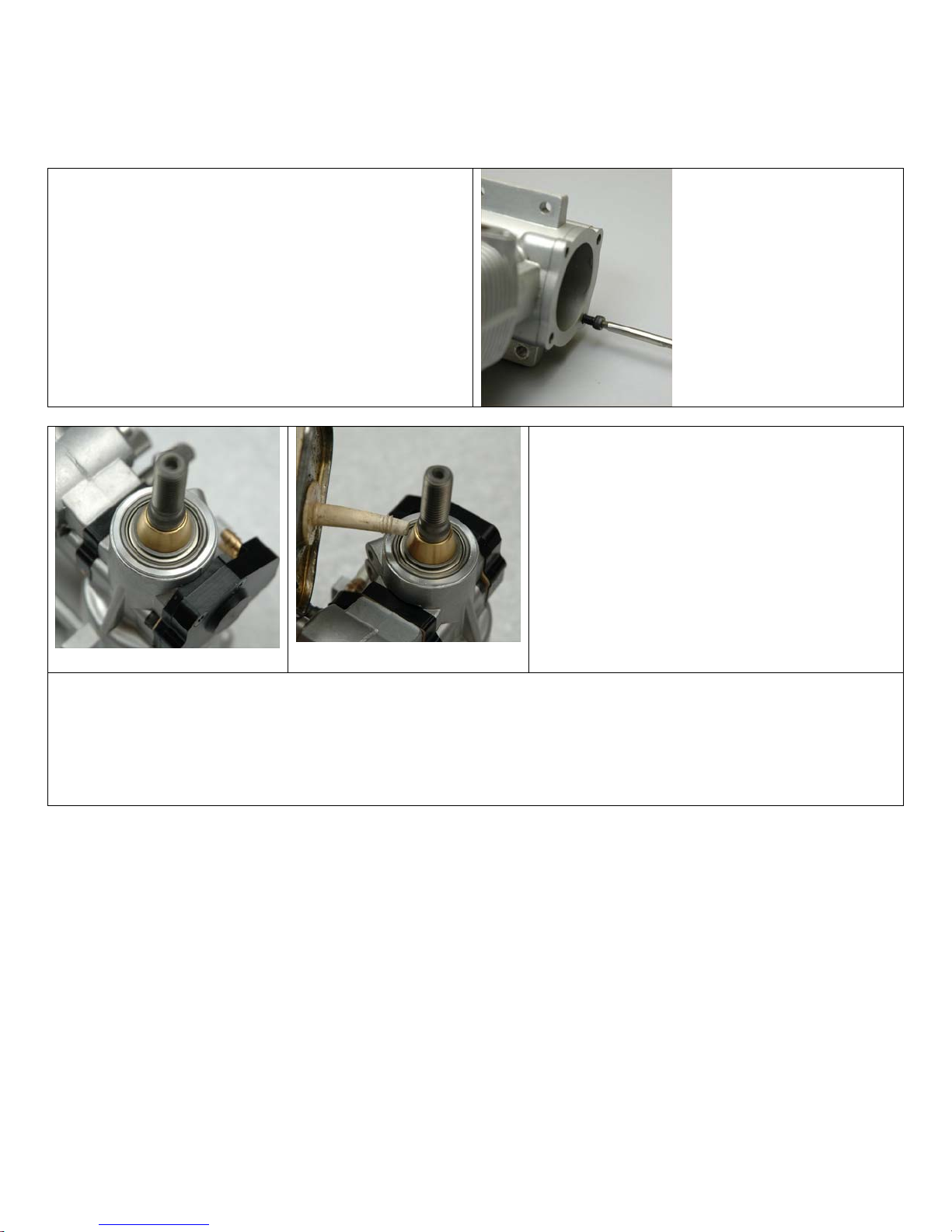
Begin by removing the crankcase rear plate bolts
from your engine using an M2.5 allen wrench. You
can store these in the box the engine came in as
you won’t need them. This kit includes bolts that
will replace them.
Do not remove the engine back plate. It must
remain on the engine for now.
For this step you will need the following
parts:
• One #0546-6 base collet
• One #0579-4 fan
• One #0331 washer
• One #0546-xx upper collet (motor
dependent)
• Two 0546-16 dampers
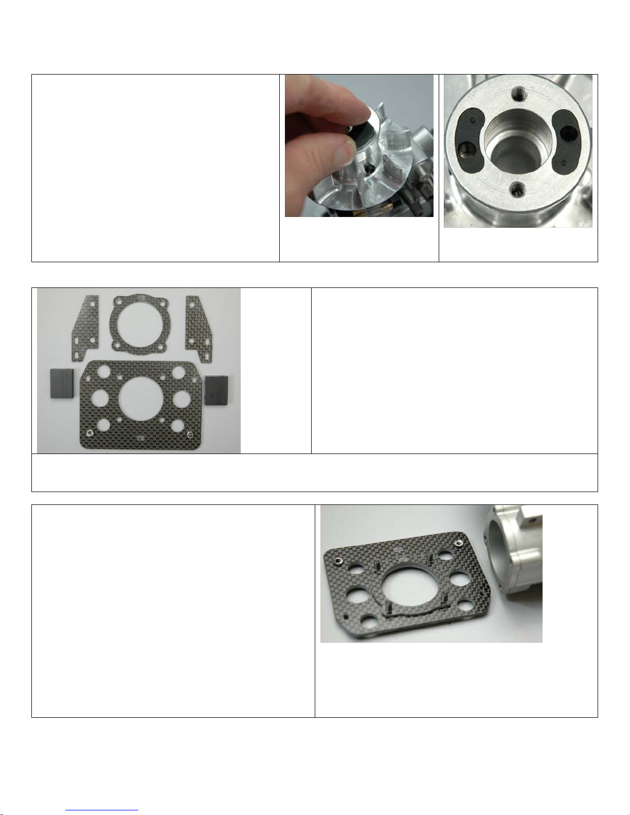
Select the 0546-6 brass base collet (it’s the
one with no recess cut into its nose).
You must install the thrust washer supplied with your motor on the crankshaft first, then slip the base
collet on and push it down against the washer and bearing. If you don’t install the thrust washer, the
spacing between the fan and clutch driver will be wrong
Place a drop of oil (of any type) on the lower collet and use your finger to smear it on the entire collet
Created: 11/1/2005 Copyright Miniature Aircraft USA Page 21 Of 188
This document may not be distributed without permission of Miniature Aircraft USA
Assembly Manual for XCell Stratus Kits #1026
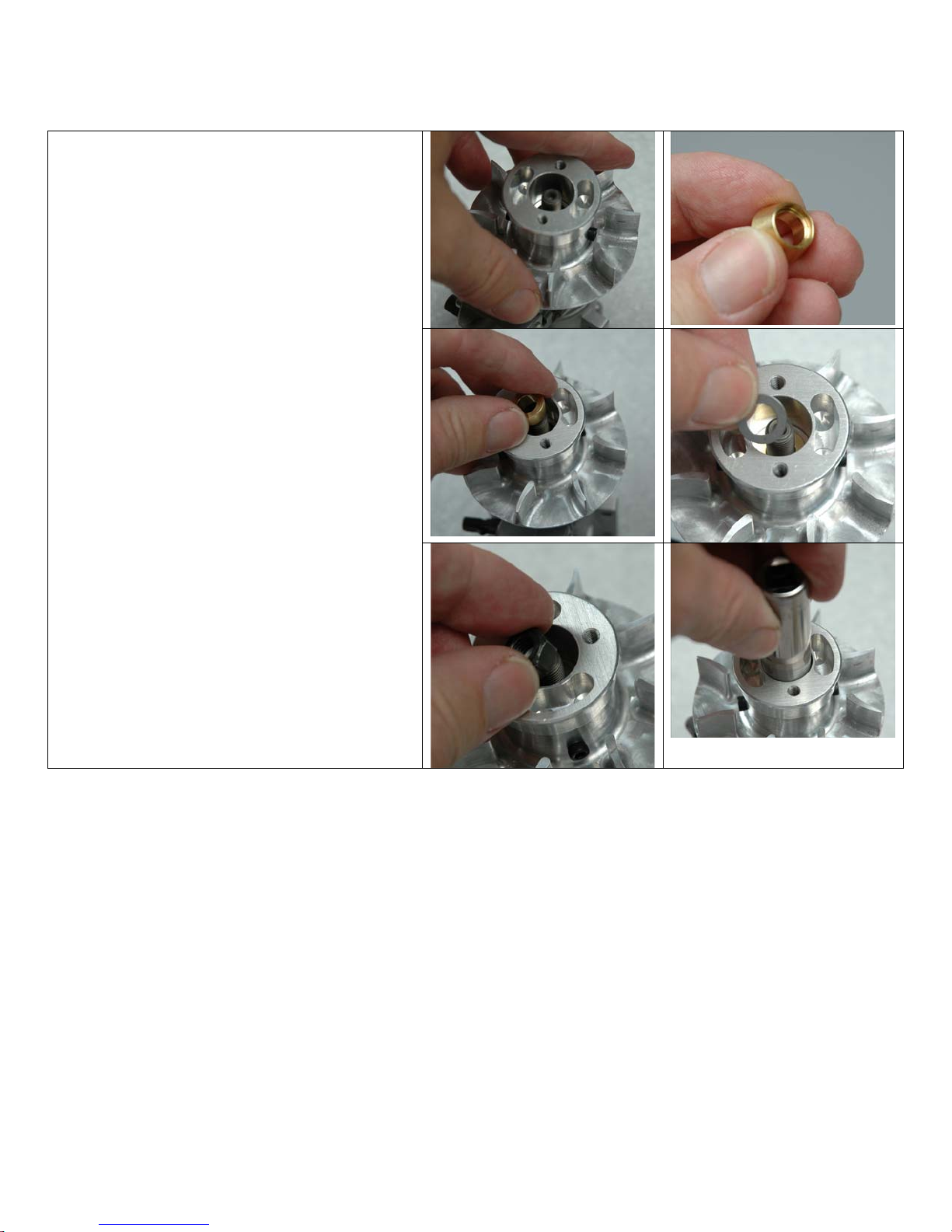
Select the 0579-4 fan and place it over the
crankshaft on the lower fan collet. Spin the
fan on the collect to distribute the lubricant
and to begin to seat it.
Select the upper fan collet. You will use the
YS collet for a YS motor and the OS collet for
an OS motor. You will not need both.
Note: The YS collet has a deeper recess and
the OS collet has a recess that is less deep.
Place the upper fan collet over the engine
crankshaft with the recess pointed
downwards towards the fan.
Select the 0331 washer and drop it over the
crankshaft
Use a toothpick to apply blue thread lock to
the threads on the end of the crankshaft
Select the engine crankshaft nut that came
with your motor and thread it onto the end of
the crankshaft
Using the correct socket, lightly snug the
engine bolt onto the washer/collet but do not
tighten yet. You will need to lock the
crankshaft in order to tighten this nut
Created: 11/1/2005 Copyright Miniature Aircraft USA Page 22 Of 188
This document may not be distributed without permission of Miniature Aircraft USA
Assembly Manual for XCell Stratus Kits #1026
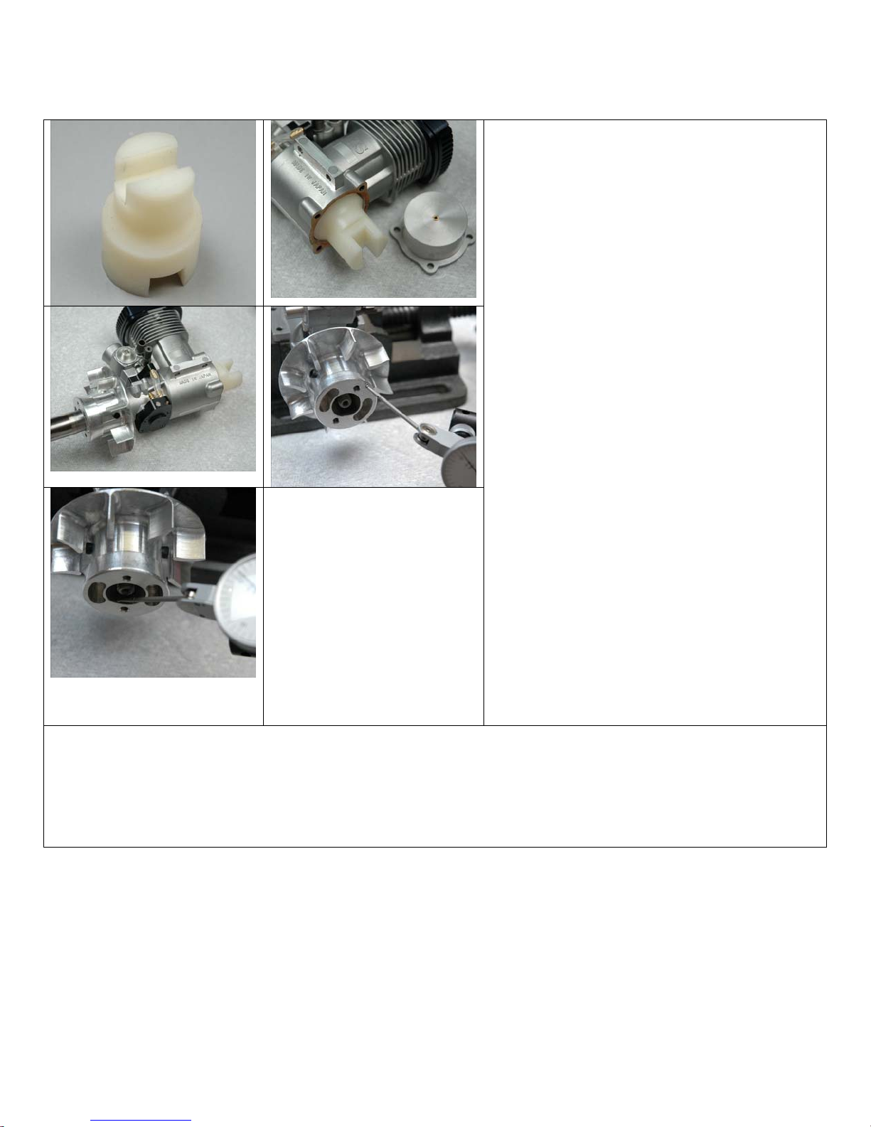
The best way to lock the crankshaft is to use
MA optional part #0511 crank lock. To use
this tool, remove the back plate from the
engine and rotate the crankshaft until the
rod/pin is located at the bottom of the
crankshaft (or the piston is at bottom dead
center). Then insert the big end of the tool
into the cavity over the rod. This will prevent
the crankshaft from turning but will not
damage any engine parts.
With the crank locked, rotate the fan on the
collets using your hand. Since you haven’t
tightened the nut yet, this will turn easily.
Using the appropriate socket for your engine,
start to tighten the crankshaft nut in several
small increments. Continue t o turn the fan on
the collets until the nut is so tight that it will
no longer turn. At this point, fully tighten the
crank/fan bolt.
It is very important that the fan “runout” is
minimal. Runout is the amount that the fan
“wobbles” on the collets. To check the runout
of the fan to see how it seated on the collets,
you will need a dial or test indicator. Remove
the crank lock and clamp the engine so that
it can’t move. Using the indicator, test the
face of the fan as well as the inside of the fan
hub. Place the tip of the indicator on the
surface and turn the fan by hand to check
total runout.
An acceptable amount of total runout is .002” or less (or +/- .001”).
If you find runout greater than this, try removing the crank nut, remove the fan and spin the fan on the
collets. Then retighten and repeat the test process. You may need to do this a few times but it should
eventually seat. If you have problems with this procedure, please contact MA for more details.
Created: 11/1/2005 Copyright Miniature Aircraft USA Page 23 Of 188
This document may not be distributed without permission of Miniature Aircraft USA
Assembly Manual for XCell Stratus Kits #1026
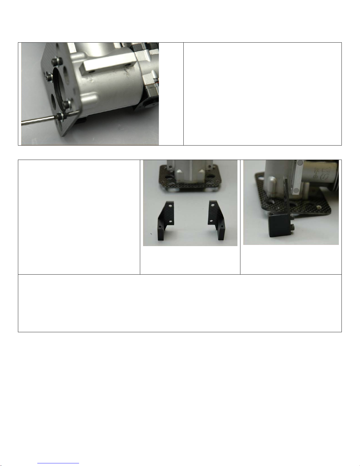
Replace the back plate in the engine but do
not reinstall the bolts that were removed
earlier.
Install the 0546-16 clutch dampers in the fan
as shown. Each damper has a small dimple.
The dampers should be installed with this
dimple facing upwards or be visible after
being inserted in the fan.
The dampers fit easily into the fan and can
be pushed in flush with the face of the fan
with finger pressure.
For these steps you will need the following parts:
• One #126-2x main base plate
• One #126-2x adapter plate
• Four #0008 M3.5 washers
• Four #0068 M3.5 bolts
The particular plates in the photos are for the YS
engine as evidenced by the letters YS engraved on
the engine back plate spacer and the engine mount
plate. The OS version will have the letters OS
engraved on them
If you are attaching an YS.80, you will also need a #126-30 adapter plate.
Select the #126-28 (YS) or #126-24 (OS) main
base plate, #126-29 (YS) or #126-25 (OS) adapter
plate, four #0068 M3.5 x 15mm bolts and four
#0008 M3.5 washers
Prepare the bottom engine mount for assembly.
Align the plates and engine as shown. The engine
initials (YS or OS) should be facing up on both
plates and should be next to each other. Slide one
M3.5 washers over each of the M3.5 x 15mm bolts
and then insert them from the bottom of the plate
such that they pass through the engine back plate
spacer. The engine will be assembled on the same
side as the initials, such that the cylinder covers the
initials.
Created: 11/1/2005 Copyright Miniature Aircraft USA Page 24 Of 188
This document may not be distributed without permission of Miniature Aircraft USA
Assembly Manual for XCell Stratus Kits #1026
Apply a small amount of blue Thread lock to the
exposed part of the bolts and attach the combined
plates onto the engine back plate as shown.
Tighten all four bolts, tightening alternate bolts
one at a time in an X pattern. The purpose of this
is to more evenly tighten the plate.
For these steps you will need the
following parts:
• Two #126-23 motor side
mounts
• Two #126-86 corner blocks
• Two #0060-1 M3 x 6mm
socket head bolts
• Four #0080 M4 x 14mm bolts
• Four #0021 M4 Locknuts
Select two #126-23 carbon motor side
mounts, two #126-86 corner blocks,
and two #0060-1 M3 x 6mm socket
head bolts.
Assemble the two engine side mounts as shown. Assemble the flat engine mount plates to the aluminum
mount blocks using 2 each M3 x 6mm bolts in each block. No washers are used. At this time only lightly
tighten them. Do not fully tighten them yet or apply Thread lock. The plates and blocks are not marked
left or right but must be assembled as shown.
Note how the assemblies will fit on the engine mount plate and again st the engine.
Created: 11/1/2005 Copyright Miniature Aircraft USA Page 25 Of 188
This document may not be distributed without permission of Miniature Aircraft USA
Assembly Manual for XCell Stratus Kits #1026
Select four #0080 M4 bolts and four #0021 M4 locknuts
Mount both of the assembled engine side mounts to the
engine using the M4 bolts and M4 locknuts. No washers are
used At this time just snug the bolts, do not fully tighten them
yet.
At this point in the assembly, the aluminum blocks are just
sitting on the bottom plate. They will be attached in the next
step
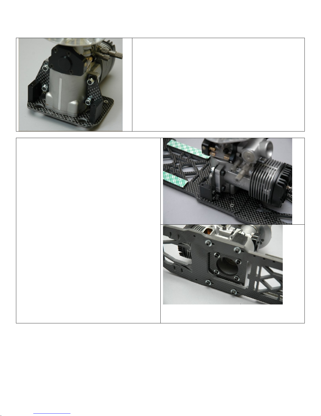
For these steps you will need the following parts:
• One #126-20 main base plate
• Two #0067 M3 x 14mm socket head screws
• Two #0063 M3 x 10 socket head screws
• Four #0003 M3 flat washers
Select the #126-20 main base plate, two #0067 M3
x 14 socket head screws, two #0063 M3 x 10
socket head screw and four #0003 flat washers.
Orient the main base plate so that the recessed
portion faces down (or the pre-installed two sided
tape faces up).
Attach the assembled engine mount to either side
of the bottom frame plate oriented as shown. The
engine will be facing the front part of the plate
which is noted by the square opening. The X
opening in the plate is the rear of the plate.
Use 2 each M3 x 14mm bolts and flat washers
through the rear slotted openings into the
aluminum engine mount blocks. Use 2 each M3 x
10mm bolts and flat washers through the front
slotted openings into the PEM nuts on the engine
mount plate. Tighten all 4 bolts but do not use
Thread lock yet.
Created: 11/1/2005 Copyright Miniature Aircraft USA Page 26 Of 188
This document may not be distributed without permission of Miniature Aircraft USA

Assembly Manual for XCell Stratus Kits #1026
First tighten each of the four M3 bolts
that attach the aluminum side engine
mount blocks. When complete, remove
them one at a time, apply blue Thread
lock and then reinstall and tighten them.
Then tighten the four M4 engine bolts and
locknuts
Slightly loosen the four bolts that attach
the engine mount plate to the bottom
plate so that the entire engine assembly
can be repositioned in the slots on the
bottom plate. Leave these bolts loose
until the engine alignment is done in a
later step
For this step you will need the following
parts:
• Two #0586-16 corner blocks
• Two #126-73 lower shroud mounts
• Six #0060-1 M3 x 6mm bolts
• Four #0063 M3 x 10mm bolts
Select two #0586-16 corner blocks, two
#126-73 lower fan shroud mounts, six
#0060-1 M3 x 6mm socket head bolts and
four #0063 M3 x 10mm socket head bolts.
The lower mounts will be assembled as
shown in the photo.
Attach each of the lower fan shroud mounts
to the corner blocks using two 6mm bolts as
shown. Tighten only enough that the shroud
mounts are flat against the corner block but
can move fore and aft freely. These bolts will
be tightened in a later step
Created: 11/1/2005 Copyright Miniature Aircraft USA Page 27 Of 188
This document may not be distributed without permission of Miniature Aircraft USA
Assembly Manual for XCell Stratus Kits #1026
This step will install the fan shroud mount brackets onto the bottom plate
assembly.
Insert two of the 10mm bolts through the right set of slotted holes on the
bottom plate from the bottom. Tighten so that the corner block is against
the bottom plate, but can move freely side to side in the slots.
Repeat this procedure on the left side of the bottom plate.
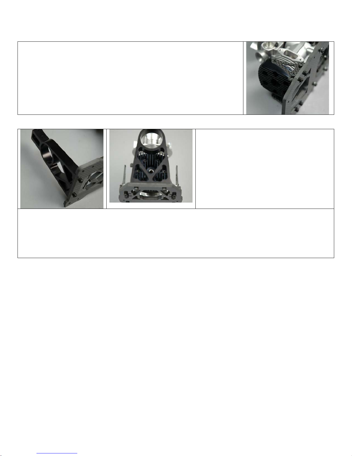
For this step you will need the following
parts:
• Two #126-26 A frame supports
• Four #0065 M3 x 12mm bolts
• Previously assembled bottom plate
Select two #126-26 A frame supports and
four #0065 M3 x 12mm socket head bolts.
Install the frame ladder supports onto the top of the bottom plate on each end. The wide end of the ladder
support installs against the bottom plate. The ladder supports can face either direction the dimensions are
symmetrical. Insert the two M3 bolts to attach each frame support as shown.
At this time, lightly tighten these bolts only.
Created: 11/1/2005 Copyright Miniature Aircraft USA Page 28 Of 188
This document may not be distributed without permission of Miniature Aircraft USA

Assembly Manual for XCell Stratus Kits #1026
For this step you will need the following
parts:
• Two #115-30 velcro
• Previously assembled bottom plate
Select the #115-30 – 28” piece of Velcro.
Fold it in half and cut it into two equal pieces
using a pair of scissors
Insert each of the two equal pieces from the
bottom of the bottom plate, through the tank
support mount slots. There are two slots
towards the front of the plate and four slots
towards the back of the plate. For the holes
at the back of the plate, use the two forward
slots.
Arrange the Velcro such that equal portions
are extended through all four of these slots
as shown
Created: 11/1/2005 Copyright Miniature Aircraft USA Page 29 Of 188
This document may not be distributed without permission of Miniature Aircraft USA
Assembly Manual for XCell Stratus Kits #1026
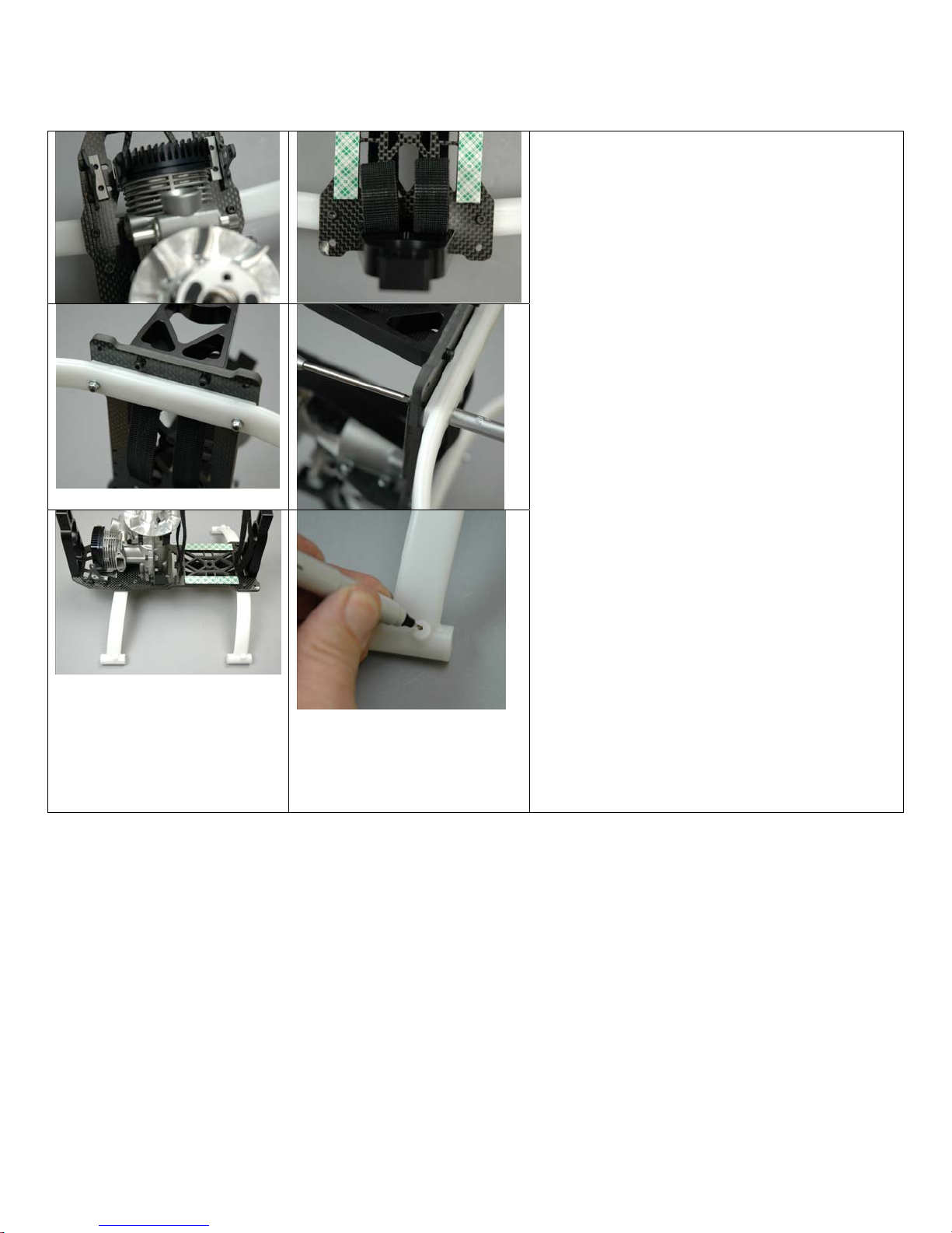
For this step you will need the following
parts:
• Previously assembled bottom plate
• Four #0073 M3 x 20mm bolts
• Two #0151 Landing gear struts
• Four #0009 M3 washers
• Four #0019 M3 locknuts
Insert two #0073 M3 x 20 socket head bolts
from the top of the bottom plate through the
two landing gear mount holes towards the
front of the bottom plate as shown. Attach
one of the #0151 struts on the bottom of the
plate over the two bolts and using two
#0009 M3 washers
and two #0019 locknuts. Do not fully tighten
at this time.
Now insert the remaining M3 x 20 bolts from
the top of the bottom plate, through the two
landing gear mount holes towards the back
of the bottom plate as shown. Attach the
remaining strut over these two exposed bolts
using the remaining #0009 washers and M3
locknuts. Do not fully tighten at this time.
The completed assembly with both struts
installed will appear as shown
Using a marking tool, make a mark at the
center of each of the bosses found on the top
of the bottom part of each landing gear strut
as shown.
Created: 11/1/2005 Copyright Miniature Aircraft USA Page 30 Of 188
This document may not be distributed without permission of Miniature Aircraft USA
 Loading...