

miniature aircraft X-Cell Furion 6 Assembly Instructions Manual

ASSEMBLY INSTRUCTIONS
Step up to Excellence with X-cell

2

Table of Contents
Kit Introduction ..................................................................................................................................................4
R/C Helicopter Safety .........................................................................................................................................4
Warning .................................................................................................................................................................... 4
General Guidelines ...................................................................................................................................................
Academy of Model Aeronautics (AMA) ............................................................................................................5
Kit Assembly ........................................................................................................................................................ 6
Required Tools ......................................................................................................................................................... 6
Optional Tools ..........................................................................................................................................................
Other Required Components ....................................................................................................................................
Assembly Tips ......................................................................................................................................................7
Kit Contents .........................................................................................................................................................8
Bag 1 Assembly ..................................................................................................................................................10
Bag 1 Hardware ......................................................................................................................................................10
Bag 1 Pre-Assembled Parts List .............................................................................................................................
Bag 1 Assembly Instructions ..................................................................................................................................
Bag 1 Completed Assembly Diagram ....................................................................................................................
10
11
23
4
6
6
Bag 2 Assembly ..................................................................................................................................................24
Bag 2 Hardware ......................................................................................................................................................24
Bag 2 Pre-Assembled Parts List .............................................................................................................................
Bag 2 Assembly Instructions ..................................................................................................................................
Bag 2 Completed Assembly Diagram ....................................................................................................................
24
25
32
Bag 3 Assembly ..................................................................................................................................................33
Bag 3 Hardware ......................................................................................................................................................33
Bag 3 Assembly Instructions ..................................................................................................................................
Electronics Installation ...........................................................................................................................................
33
38
Bag 4 Assembly ..................................................................................................................................................40
Bag 4 Hardware ......................................................................................................................................................40
Bag 4 Pre-Assembled Parts List .............................................................................................................................
Bag 4 Assembly Instructions ..................................................................................................................................
40
41
Completed Assembly Diagram ......................................................................................................................... 48
Control Rod Length Diagram ..........................................................................................................................48
Basic Model/Radio Set Up ................................................................................................................................49
Swashplate eCCPM Set Up .............................................................................................................................. 50
Pitch Curve Set Up ............................................................................................................................................ 51
Throttle Curve Set Up ......................................................................................................................................52
Choosing Your Power System ..........................................................................................................................52
Kit Hardware and Parts ...................................................................................................................................53
Warranty Information ...................................................................................................................................... 55
3

Kit Introduction
Thank you for purchasing the X-Cell Furion 6 by Miniature Aircraft USA. This model is the culmination
of years of designing and manufacturing R/C helicopters. It is designed with the highest standards, and will
provide years of enjoyment. Whether this is your first R/C model helicopter or you are an advanced R/C
helicopter modeler, the X-Cell Furion 6 is a fantastic choice for a “600 size” model.
R/C Helicopter Safety
A radio controlled model helicopter is not a toy, but rather a technically complex device that must be built
and operated with care. It is also a fascinating and challenging part of the R/C sport, the mastery of which is
very rewarding. A model helicopter must be built exactly in accordance with the building instructions. The kit
manufacturer has spent much time and effort refining his product to make it reliable in operation and easy to
build. The essentially bolt together construction can proceed quite rapidly, giving the builder a strong sense of
accomplishment that encourages hasty progress from one construction phase to the next, so that the completed
model can be more quickly seen and enjoyed. It is essential to recognize and guard against this tendency.
Follow building instructions exactly. Vibration and stress levels are high and all fasteners and attachments must
be secure for safe operation.
Note that this is the first use of the word SAFETY in these comments. Previously the kit manufacturer’s efforts to ensure reliable
operation were mentioned. That is ALL that he can do. Safe operation is the responsibility of the builder/flyer and starts with careful
construction and continues with selection and installation of reliable radio equipment and engine.
The need for safety is nowhere greater than at the flying field. A number of guidelines for safe flight have been
developed by experienced flyers and are set down here. It is urged that they be read, understood and followed.
Warning! – Risk of death or serious injury
Remote Control (“R/C”) Helicopters can be dangerous. Inexperienced pilots of R/C Helicopters should be
trained and supervised by experienced operators. All operators should use safety glasses and other appropriate
safety equipment, and exercise necessary precautions when fueling, repairing, maintaining, flying and
storing R/C Helicopters, and when using or storing R/C Helicopter accessories, equipment, fuels, and related
materials. R/C Helicopters should be used only in open areas free of obstacles, and far enough from people to
minimize the possibility of injury from the helicopter or any of its components falling or flying in unexpected
directions.
This helicopter is not a toy, but a complex flying machine that must be assembled with care by a responsible
individual. Failure to exert care in assembly, or radio or accessory installation, may result in a model incapable
of safe flight or ground operation. Rotating components are an ever present danger and source of injury to
operators and spectators. Since the manufacturer and his agents have no control over the proper assembly and
operation of his products, no responsibility or liability can be assumed for their use.
General Guidelines for Safe R/C Helicopter Flight
• Fly only at approved flying fields and obey field regulations.
• Follow frequency control procedures. Interference can be dangerous to all.
• Know your radio. Check all transmitter functions before each flight.
• Be aware that rotating blades are very dangerous and can cause serious injury.
• Never fly near or above spectators or other modelers.
• If you’re a beginner, get help trimming the model first and flight training later.
• Don’t “track” the main blades by holding the tail boom. This is a temptation to builders who cannot hover yet
and is very dangerous.
• Follow all recommended maintenance procedures for model, radio and engine.
4

Academy of Model Aeronautics
Miniature Aircraft USA highly recommends joining the Academy of Model Aeronautics (AMA).
• AMA is the Academy of Model Aeronautics.
• AMA is the world’s largest model aviation association, representing a membership of more than 150,000
from every walk of life, income level and age group.
• AMA is a self-supporting, non-profit organization whose purpose is to promote development of model
aviation as a recognized sport and worthwhile recreation activity.
• AMA is an organization open to anyone interested in model aviation.
• AMA is the official national body for model aviation in the United States. AMA sanctions more than a
thousand model competitions throughout the country each year, and certifies official model flying records on
a national and international level.
• AMA is the organizer of the annual National Aeromodeling Championships, the world’s largest model
airplane competition.
• AMA is the chartering organization for more than 2,500 model airplane clubs across the country. AMA offers
its chartered clubs official contest sanction, insurance, and assistance in getting and keeping flying sites.
• AMA is the voice of its membership, providing liaison with the Federal Aviation Administration, the Federal
Communications Commission, and other government agencies through our national headquarters in Muncie,
Indiana. AMA also works with local governments, zoning boards, and parks departments to promote the
interests of local chartered clubs.
• AMA is an associate member of the National Aeronautic Association. Through NAA, AMA is recognized by
the Fédération Aéronautique Internationale (FAI), the world governing body of all aviation activity, as the
only organization which may direct U.S. participation in international aeromodeling activities.
For more detailed information, contact the Academy of Model Aeronautics
5161 E. Memorial Drive, Muncie, Indiana, 47302
or telephone (800) 435-9262.
You may also visit the AMA website at www.modelaircraft.org
5

Kit Assembly
Your Furion 6 kit will require a number of different supplies and tools to ensure the best final result. They are
as follows:
Required Lubricants and Compounds:
1. Medium Strength Thread Locking Compound - X-Cell Super Lock Blue (MA3200-20)
2. Tri-Flow Oil (MA3200-02)
3. Tri-Flow Synthetic Grease (MA3200-06)
4. Medium Cyanoacrylate (CA)
5. Retaining Compound - X-Cell Super Lock Green (MA3200-22)
Required Tools:
1. m4 Nut Driver
2. m5 Nut Driver
3. m5.5 Nut Driver
4. m7 Nut Driver
5. 1.5mm Allen Driver
6. 2.0mm Allen Driver
7. 2.5mm Allen Driver
8. 3.0mm Allen Driver
9. Needle Nose Pliers
10. Phillips Screwdriver #1
11. Flat Screwdriver 2.5mm
12. Razor Knife (X-acto)
13. Snap Ring Pliers
Optional Tools:
1. Swashplate Leveling Tool (MA3000-10)
2. Pitch Gauge (MA3000-06)
3. Flybar Alignment Gauge (MA3000-08)
5. Furion 6 Head Set Up Tool (MA3000-02)
6. Optical Heli Tachometer (MA3000-50)
Other required components:
The X-Cell Furion 6 is an airframe kit. To complete the model, several other items are required but are not
included with the kit. There are many choices for these other required components, and any competent hobby
retailer with R/C helicopter experience will be happy to make suggestions. You will need:
1. Brushless electric motor (6S KV Range 850-900 or 10S KV Range 540-560).
Motor shaft dimension 6mm x 30/32mm
2. Electronic Speed Control (ECS) suitable for use in R/C helicopters
3. Lithium Polymer Batteries: 6 cell 5000mah or 10 cell (2 x 5S) 4000-5000mah setups are recommended
4. Cyclic servos (Miniature Aircraft USA recommends high quality cyclic servos with no less than 80 oz.
in. of torque.)
5. R/C helicopter gyro (Miniature Aircraft USA recommends a “heading hold” style gyro)
6. Rudder servo suitable for use with the gyro you choose.
7. R/C helicopter transmitter and receiver with at least 6 channels, and eCCPM capabilities.
8. Receiver battery pack, or BEC
6

Important Assembly Tips - PLEASE READ
• Follow the instructions. The methods of construction documented in this manual have been proven to work.
Do not rush the build of your model! You have purchased a world class model helicopter kit, take your
time and realize that the final result is now up to you. Take the time to fully understand each step, if you are
unsure please contact Miniature Aircraft USA.
• Follow the order of assembly. The instructions have been organized into major sections and have been written
in such a way that each step builds upon the work done in the previous step. Changing the order of assembly
may result in unnecessary steps.
• Clean all metal parts: All of the steel parts in this kit are coated with a lubricant to prevent them from rusting.
This coating can interfere with the adhesives and thread locks needed for assembly. Use a solvent such as
alcohol or acetone to clean the various metal parts, especially threads.
• Use thread lock as indicated. Generally, any bolt or screw that threads into a metal part requires thread lock.
Model helicopters are subject to vibration and failing to use thread lock on any non-locking assembly may
result in a part becoming loose or falling off.
7

Kit Contents
Please take some time to familiarize yourself with the contents of the kit. The Furion 6 kit has been broken
down into four “bags”. Each bag contains parts and hardware. The hardware for each bag will be used only
for that bag. There will be no left over parts after each bag is assembled.
Bag Part No. Part Description Qty
1-A 129-10 C/F Right Main Frame w/pems 1
1-A 129-13 C/F Left Main Frame w/pems 1
1-A 129-16 G-10 Antirotation Guide w/pems 1
1-A 129-19 C/F Left Servo Mount .125” 1
1-A 129-22 C/F Right Servo Mount .125” 1
1-A 129-25 C/F Gyro Plate .062” 1
1-A 129-28 C/F Electronic Plate .062” 1
1-A 129-31 C/F Boom Mount Brace .062” 1
1-A 129-34 C/F Battery Plate .062” 1
1-A 129-37 C/F Canopy Break-away Mounts .062” 4
1-B 0586-16 Corner Block 2
1-B 128-40 Lower Mainshaft Block w/Bearing 1
1-B 128-57 Aluminum Tray Mounts 4
1-B 128-58 Frame Spacers 4
1-B 128-61 Rear Canopy Mounts 2
1-B 128-62 Front Canopy Mounts 2
1-B 128-65 Landing Gear Mounting Block 4
1-B 128-67 Pulley Mount 1
1-B 128-70 Aluminum Idler Pulleys - Assembled 2
1-B 128-80 Aluminum Boom Clamps 2
1-B 129-40 Upper mainshaft Block w/Bearing 1
1-B 129-43 Battery Mount Rails 2
1-B 129-46 Knurled Thumb Screw 4
1-B 129-49 9/16” Rubber Wire Grommets 3
1-B 129-64
1-C 127-53 Plastic Struts 2
1-C 127-54A Skid Plugs 4
1-C 128-66 Aluminum Skids 2
1-C 129-38 C/F Strut Support .062” . 2
1-D 0875-1 Main Shaft Collar 1
1-D 128-43 Main Shaft 1
1-D 128-47 600T T/R Drive Belt 1
1-D 128-49 Autorotation Hub 1
1-D 129-52 54T T/R Drive Pulley 1
1-D 129-55 109T Main Gear 1
1-D 129-61 129-61 Motor Mount 1
1-D 129-69 12 Tooth Pinion Gear 1
1-D 129-70 13 Tooth Pinion Gear 1
1-Hardware 0003 m3 Washer 10
1-Hardware 0019 m3 Locknut 4
1-Hardware 0057 m4 x 4 Socket Set Screw 2
1-Hardware 0058-1 m4 x 6 Socket Set Screw 4
1-Hardware 0058-5 m5 x 8 Dog-Point Socket Set Screw 1
Lower Motor Bearing Block w/Bearing
1
Bag Part No. Part Description Qty
1-Hardware 0058-6 m5 x 5 Socket Set Screw 1
1-Hardware 0059-1 m2.5 x 6 Socket Bolt 1
1-Hardware 0060-1 m3 x 6 Socket Bolt 78
1-Hardware 0062-2 m3 x 12 Tapered Socket Head Bolt 4
1-Hardware 0063 m3 x 10 Socket Bolt 8
1-Hardware 0064-3 m3 x 6 Button Head Socket Bolt 6
1-Hardware 0065 m3 x 12 Socket Bolt 2
1-Hardware 0067 m3 x 14 Socket Bolt 6
1-Hardware 0088-2 m3 x 6 Tapered Socket Head Bolt 2
1-Hardware 0071 m3 x 18 Socket Bolt 4
2-A 128-140 Aluminum Tail Boom 1
2-A 128-142 T/R Control Rod 1
2-A 128-148 Boom Support Assembly 2
2-A 128-193 m3 x 440 Flybar 1
2-B 127-15 13T Tailrotor Pulley 1
2-B 127-16 T/R Output Shaft 1
2-B 128-59 Front Boom Support Spacer 1
2-B 128-144 Plastic Rudder Pushrod Guides 3
2-B 128-149A Upper Rear Boom Support Clamp 1
2-B 128-149B Lower Rear Boom Support Clamp 1
2-B 128-155 Aluminum Transmission Clamp 1
2-B 128-156 m3 Threaded Bearing Stud 2
2-B 128-157 Ball Bearing T/R Idler 1
2-B 128-158 Aluminum Bellcrank Mount 1
2-B 128-161 C/F Left Tail Plate w/ Bearing 1
2-B 128-164 C/F Right Tail Plate w/ Bearing 1
2-B 129-79 C/F Vertical Fin 1
2-C 0133 Ball Link 2
2-C 0159 683zz Ball Bearing m3 x 7 x 3 2
2-C 0361 Control Ball 4
2-C 0445 Plastic T/R Bellcrank 1
2-C 0446-4 .165” x .310” x .003” S/S Shim 2
2-C 0457 F4-10m Thrust Bearing 3 pc. 2
2-C 0597-3 3/16” x .182” Brass Spacer 1
2-C 0873-1 Plastic T/R Blade Mounts 2
2-C 120-39 m5 x 10 x 4 Ball bearing 2
2-C 122-65 Steel Tail Hub 1
2-C 128-159 T/R Pitch Slider Assembly 1
2-C 128-166 Plastic T/R Blades 2
2-C 3700-155 Delrin T/R Blade Spacers 4
2-Hardware 0001 m2 Washer 2
2-Hardware 0016-1 m4 External Serrated Lock-Washer 4
2-Hardware 0017 m3 Hex Nut 1
8

Kit Contents
Bag Part No. Part Description Qty
2-Hardware 0019 m3 Locknut 2
2-Hardware 0021 m4 Locknut 2
2-Hardware 0049-3 m2 x 8 Socket Bolt 4
2-Hardware 0053 m3 x 5 Socket Set Screw 1
2-Hardware 0056 m3 x 5 Dog-Point Socket Set Screw 3
2-Hardware 0060-1 m3 x 6 Socket Bolt 9
2-Hardware 0065 m3 x 12 Socket Bolt 3
2-Hardware 0064-9 m4 x 10 Button Head Socket Bolt 4
2-Hardware 0091 m3 x 16 Phillips Bolt 1
2-Hardware 0097 m3 x 22 Phillips Bolt 2
3-A 0107 m3 x 6 Threaded Control ball 3
3-A 0109 m3 x 8 Threaded Control Ball 4
3-A 0112 m3 x 9.4 Threaded Ball 2
3-A 0159 m3 x 7 x 3 Ball Bearing 4
3-A 0217 Swashplate 1
3-A 0219 Plastic Washout Hub 1
3-A 0221 Plastic Washout Arms 2
3-A 0597-2 Brass Spacer 2
3-A 0869 Plastic Washout Link 2
3-A 129-88 Swashplate Guide Pin 1
3-A 128-176 m2 x .584” Washout Pivot Pins 2
3-B 0103 m2 x 5 Threaded Control Ball 4
3-B 0133 Plastic Ball Links 6
3-B 0337 m2 x 30 Threaded Control Rod 3
3-B 120-99 Knurled Canopy Knob 2
3-B 128-36 C/F Servo Arm Alignment Gauge 1
3-B 128-170 Plastic Servo Blocks 2
3-B 128-172 G-10 Servo Retainers 1
3-B 128-173 .090” Carbon Cyclic Servo Spacers 1
3-B 3200-46 1/2” x 15” Back to Back Velcro 1
3-B 3200-48 3/4” x 25” Back to Back Velcro 1
3-B 3200-54
3-B 115-94 Rear Canopy Grommets 2
3-B 106-22 Front Canopy Grommets 2
3-Hardware 0015 m2 Hex Nut 4
3-Hardware 0038 M2.5 x 10 Phillips Bolt 4
3-Hardware 0039-1 m2.5 x 14 Phillips Bolt 8
3-Hardware 0039-2 m2.5 x 16 Phillips Bolt 4
3-Hardware 0051 m3 x 3 Socket set Screw 3
3-Hardware 0071 m3 x 18 Socket Head Bolt 2
3-Hardware 0097 m3 x 22 Phillips Bolt 2
3-Hardware 0447-1 m1.5 E-Clips 2
4-A 0112 m3 x 9.5 Threaded Control Ball 2
4-A 0133 Ball Link 4
4-A 0337 m2 x 30 Threaded Control Rod 2
4-A 128-180 Head Block Assembly 1
3/4” Adhesive Back Hook & Loop Velcro
1
Bag Part No. Part Description Qty
4-A 128-189 Flybar Control Bar 2
4-A 128-190 Flybar Paddles 2
4-A 128-192 Flybar Control Arm with Base 2
4-A 128-195 Head Button 1
4-B 0109 m3 x 8 Threaded Control Ball 2
4-B 0112 m3 x 9.5 Threaded Control Ball 2
4-B 128-188 Plastic Main Blade Grip w / 0319 Brg. 2
4-B 128-196 3-D Bell Mixer Assembly 2
4-C 0133-1 Grey Ball Links 8
4-C 0319 m8 x 16 x 5 Ball Bearing 2
4-C 0324 m10.75 x 16 x 1 Washer 2
4-C 0331 m8 x 14 x .5 Shim Washer 4
4-C 0332 m8 x 14 x 1 Shim Washer 2
4-C 0840-12 3 pc. Thrust Bearing 2
4-C 0844-6 90D Head Dampener O-Rings 4
4-C 0848-2 m8 Retaining Clips 2
4-C 0848-9 Clip Application Tool 1
4-C 120-7 C/F Washer m5 x 15.5 2
4-C 120-25 m3 x 86 Threaded Control Rod 2
4-C 128-187 Head Axel 8mm 1
4-C 128-198 m3 x 16 Dowel Pin 1
4-C 3700-150 Nylon Blade Washers 4
4-Hardware 0021 m4 Locknut 2
4-Hardware 0053-5 m3 x 16 Socket Set Screw 2
4-Hardware 0057 m4 x 4 Socket Set Screw 3
4-Hardware 0063 m3 x 10 Socket Bolt 2
4-Hardware 0064-3 m3 x 6 Button Head Socket Bolt 4
4-Hardware 0067 m3 x 14 Socket bolt 1
4-Hardware 0082 m4 x 38 Socket bolt 2
4-Hardware 0086 m5 x 12 Flanged Socket bolt 2
4-Hardware 0091 m3 x 16 Phillips Bolt 2
BOX 129-120 Canopy 1
BOX 129-130 Instruction Set 1
BOX Towel 1
9
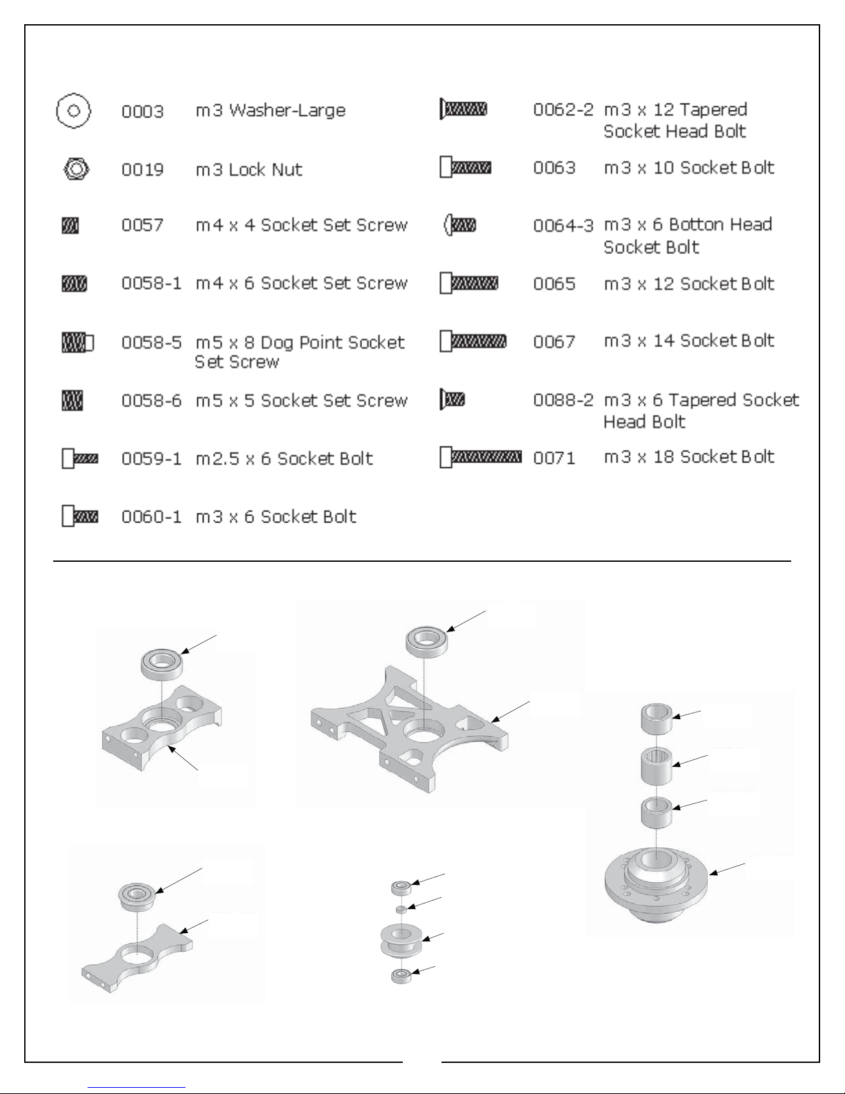
Bag 1 Hardware
Bag 1 Parts Pre-Assembled from Factory
0183
0183
128-41
128-40
Lower Main Shaft
Bearing Block
129-63
129-65
129-40
Upper Main Shaft
Bearing Block
128-71
122-28
128-73
128-71
129-39
128-49
Autorotation Hub
128-48
0208
128-48
128-49
129-64
Lower Motor Bearing Block
128-70
Aluminum Idler Pulleys
10
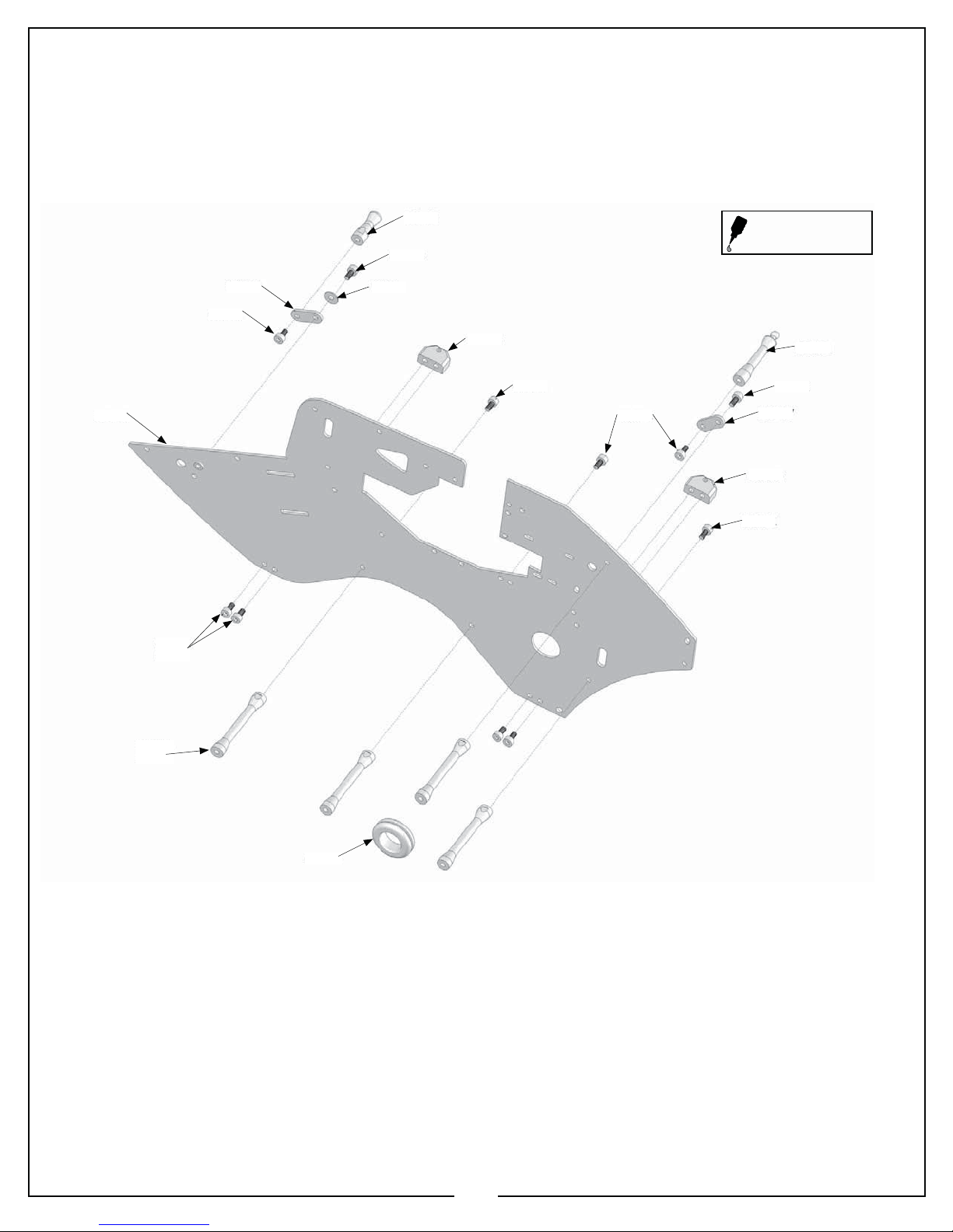
Getting Started
Bag 1
Locate bag 1, and the hardware for bag 1. Please take the time to identify the hardware for this bag. Please note that the use of
medium thread locking compound is always required when a part is threaded into metal. There may be times when the use of
thread locking compound will not be used until a later point in the build.
129-10
0060-1
4X
0060-1
128-62
0060-1
0003129-37
128-65
0060-1
0060-1
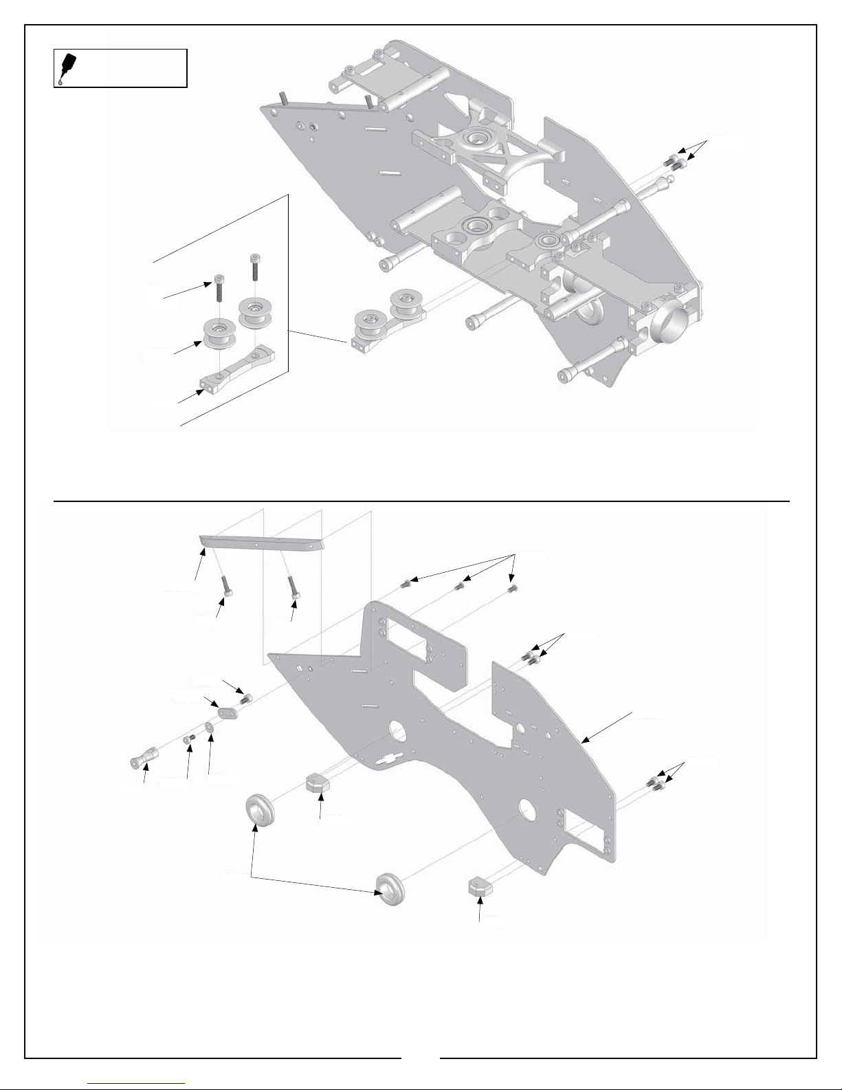
Apply a small amount of
medium thread lock when
threading into metal parts
128-61
0060-1
129-37
128-65
0060-1
128-58
4X
129-49
Illustration 1a
In this step, you will attach parts to the right main frame side. Refer to Illustration 1a for this step.
• Locate parts bags 1a, 1b, 1c, and 1d, and hardware bag 1.
• Locate the MA129-10 right side main frame from bag 1a.
• Use 4 MA0060-1 m3x6 socket head bolts to attach the two MA128-65 landing gear mounting blocks from bag 1b to the
outside of the frame as shown.
• Use 4 MA0060-1 m3x6 socket head bolts to attach 3 MA128-58 frame spacers from bag 1b as shown.
• Use 1 MA0060-1 m3x6 socket head bolt and an MA0003 m3 washer to attach the front canopy mount from bag 1b, and 1
MA0060-1 m3x6 socket bolt to attach the MA128-61 rear canopy mount from bag 1b to each of the MA129-37 canopy breakaway mounts from bag 1a as shown.
• Use 1 MA0060-1 m3x6 socket bolt to attach the front canopy mount assembly to the MA129-10 right side main frame, and
use 1 MA0060-1 m3x6 socket bolt to attach the rear canopy mount assembly to the MA129-10 right side main frame. The
rear canopy mount assembly is attached to the right side main frame assembly using an MA128-58 frame spacer from bag 1b.
Attach the front canopy mount assembly to the right main frame side into the PEM nut. A PEM nut has been installed at the
factory for this bolt to attach to.
• Insert the MA129-49 9/16” rubber wire grommet from bag 1b into the hole in the frame as shown.
11
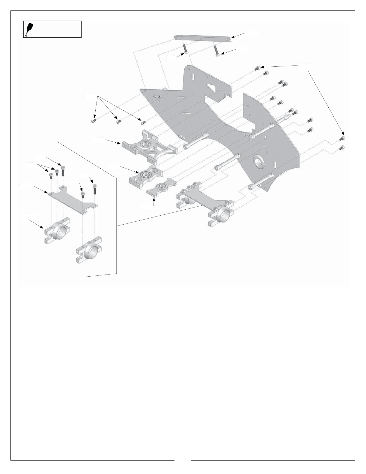
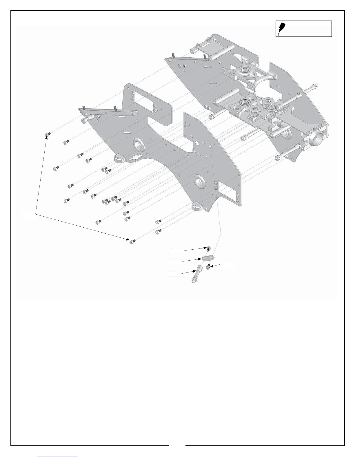
Apply a small amount of
medium thread lock when
threading into metal parts
0067
0060-1
129-31
0060-1
0067
0064-3
129-40
128-40
0065
0067
129-43
0060-1
12X
129-64
128-80
2X
Illustration 1b
In this step, you will continue to attach parts to the right main frame side. Refer to Illustration 1b for this step.
• Use Locate 1 MA129-43 battery mount rail from bag 1b and thread in 1 MA0065 m3x12 socket bolt into the front of the
MA129-43 battery mount rail, and thread in 1 MA0067 m3x14 socket bolt into the rear of the MA129-43 battery mount rail as
shown.
• Use 3 MA0064-3 m3x6 button head socket bolts and attach the battery mount rail assembly to the MA129-10 right side main
frame as shown.
• Use 4 MA0060-1 m3x6 socket bolts to attach the MA129-40 upper main shaft bearing block from bag 1b to the MA129-10
right side main frame as shown. At this point, leave the MA0060-1 m3x6 socket bolts slightly loose, and DO NOT use thread
locking compound. These will be thread locked and tightened at a later point in the build.
• Use 2 MA0060-1 m3x6 socket bolts to attach the MA128-40 lower main shaft bearing block from bag 1b to the MA129-10
right side main frame as shown. At this point, leave the MA0060-1 m3x6 socket bolts slightly loose and DO NOT use thread
locking compound. These will be thread locked and tightened at a later point in the build.
• Use 2 MA0060-1 m3x6 socket bolts and attach the MA129-64 lower motor bearing block from bag 1c as shown. At this point,
leave the MA0060-1 m3x6 socket bolts slightly loose and DO NOT use thread locking compound. These will be thread locked
and tightened at a later point in the build.
• Use 4 MA0060-1 m3x6 socket bolts and attach the two MA128-80 boom clamps from bag 1b to the right main frame
assembly. Tighten the “lower” bolts, but leave the “upper” bolts slightly loose, and DO NOT use thread locking compound at
this time. These will be thread locked and tightened at a later point in the build.
• Use 2 MA0060-1 m3x6 socket bolts, and 2 MA0067 m3x14 socket bolts to attach the MA129-31 boom mount brace from bag
1a to the two MA128-80 boom clamps. Do not fully tighten the two MA0067 m3x14 socket bolts, and DO NOT use thread
locking compound at this point. These will be thread locked, and tightened at a later point in the build.
12
0060-1
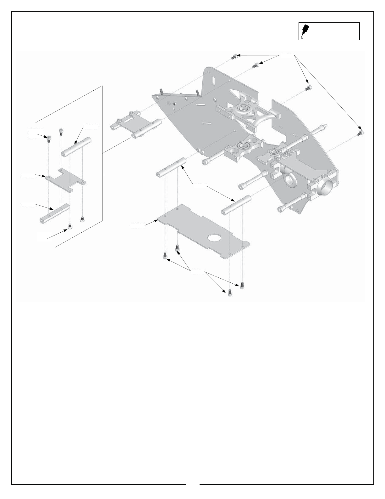
Apply a small amount of
medium thread lock when
threading into metal parts
0060-1
2X
129-25
128-57
0088-2
2X
128-57
128-57
129-28
Illustration 1c
0060-1
In this step, you will continue to attach parts to the right main frame side. Refer to Illustration 1c for this step.
• Use two MA0060-1 m3x6 socket bolts to attach the MA128-57 tray mount from bag 1b to the top of the MA129-25 c/f gyro plate
from bag 1a as shown. Note the orientation of the MA128-25 in image 1c.
• Use two MA0088-2 m3x6 tapered head socket bolts to attach an MA128-57 tray mount from bag 1b to the bottom of the MA129-25
c/f gyro plate from bag 1a as shown.
• Use two MA0060-1 m3x6 socket bolts to attach the gyro plate assembly to the right side frame assembly as shown.
• Use 4 MA0060-1 m3x6 socket bolts to attach two MA128-57 tray mounts from bag 1b to the MA129-28 electronics plate as shown.
• Use two MA0060-1 m3x6 socket bolts to attach the electronics plate assembly to the right main frame side as shown. Note the
orientation of the electronics plate assembly in Illustration 1c.
13
Apply a small amount of
medium thread lock when
threading into metal parts
0067
2X
128-70
0060-1
128-67
Illustration 1d
In this step, you will assemble and install the idler pulley assembly. Refer to Illustration 1d for this step.
• Use two MA0067 m3x14 socket bolts to attach the MA128-70 aluminum idler pulleys from bag 1b to the MA128-67 aluminum
pulley mount from bag 1b as shown. Note the orientation of the pulley mount assembly as shown.
• Use two MA0060-1 m3x6 socket bolts to attach the aluminum idler pulley assembly to the right main frame assembly as shown.
0064-3
129-43
128-62
129-37
0060-1
0065
0060-1
0003
0067
0060-1
129-13
0060-1
129-49
In this step, you will attach parts to the left main frame side. Refer to Illustration 1e for this step.
• Use four MA0060-1 m3x6 socket bolts to attach two MA128-65 landing gear mounting blocks from bag 1b to the outside of the
MA129-13 left side main frame as shown.
• Use Locate 1 MA129-43 battery mount rail from bag 1b and thread in 1 MA0065 m3x12 socket bolt into the front of the MA12943 battery mount rail, and thread in 1 MA0067 m3x14 socket bolt into the rear of the MA129-43 battery mount rail as shown.
• Use 3 MA0064-3 m3x6 button head socket bolts and attach the battery mount rail assembly to the MA129-10 right side main
frame as shown.
128-65
Illustration 1e
128-65
14
Apply a small amount of
medium thread lock when
threading into metal parts
0060-1
22x
0060-1
129-37
128-61
0060-1
Illustration 1f
In this step, you will continue to attach parts to the left main frame side, and join the left main frame side to the right main frame
side. Refer to Illustration 1f for this step.
• Use 1 MA0060-1 m3x6 socket head bolt and an MA0003 m3 washer to attach the front canopy mount from bag 1b, and 1
MA0060-1 m3x6 socket bolt to attach the MA128-61 rear canopy mount from bag 1b to each of the MA129-37 canopy breakaway mounts from bag 1a as shown.
• Use 1 MA0060-1 m3x6 socket bolt to attach the front canopy mount assembly to the MA129-13 left side main frame. A PEM
nut has been installed at the factory for this bolt to attach to.
• Insert two MA129-49 9/16” rubber wire grommets into the left side frame assembly as shown.
• Use 22 MA0060-1 m3x6 socket bolts to attach the left side main frame assembly to the right side main frame assembly. Please
note: Do not apply thread locking compound to the MA0060-1 m3x6 socket bolts going into the upper and lower bearing
block or the lower motor bearing block. These will be thread locked and tightened at a later point in the build.
• Use an MA0060-1 m3x6 socket bolt to attach the rear canopy mount assembly. This socket bolt will thread into the frame
spacer, as shown.
15
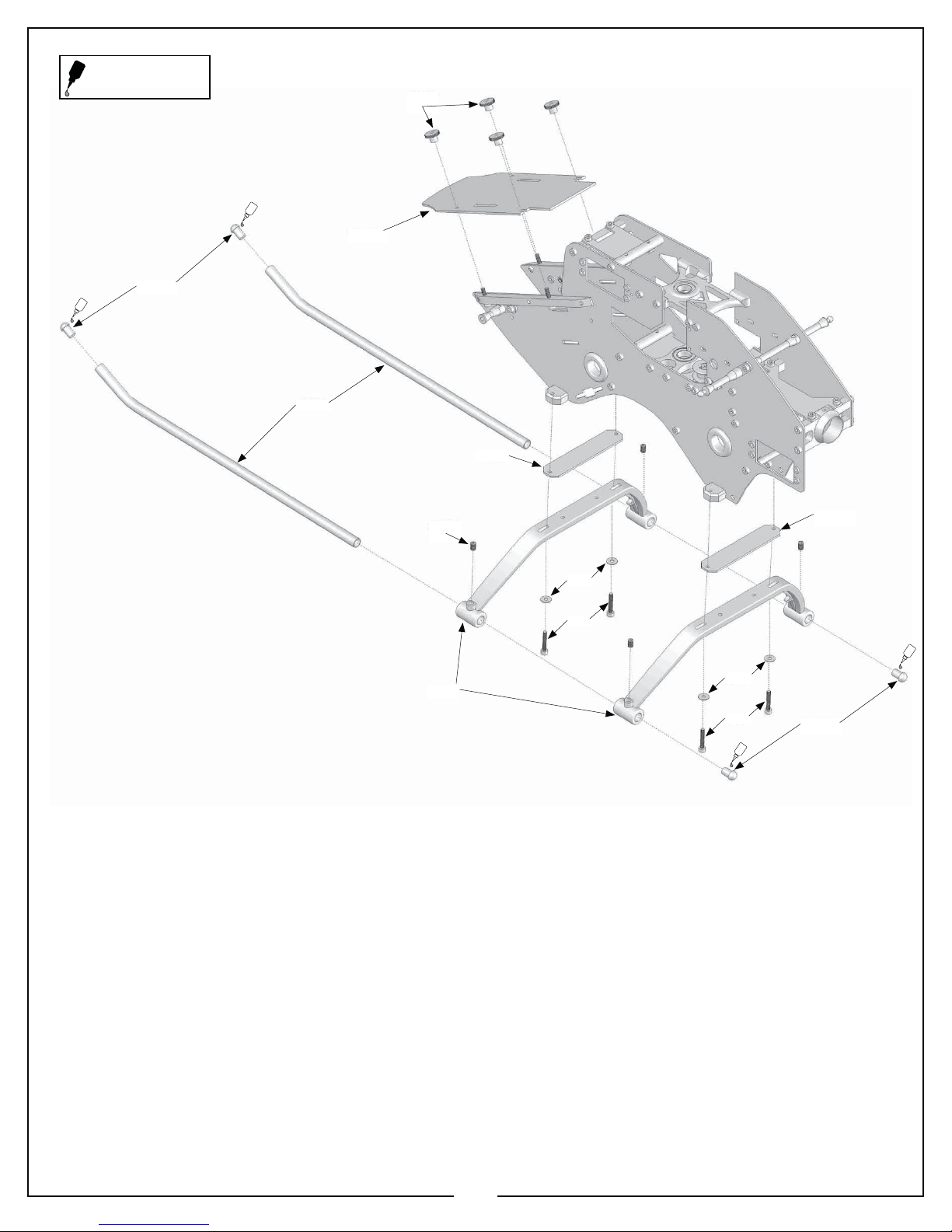
Apply a small amount of
medium thread lock when
threading into metal parts
CA
129-34
129-46
4X
CA
127-54A
Illustration 1g
128-66
0058-1
4x
127-53
129-38
0003
0071
CA
0003
0071
129-38
CA
127-54A
In this step you will attach the battery tray, and landing gear assembly to the main frame assembly. Refer to Illustration 1g for this
step.
• Use four MA0071 m3x18 socket bolts, and four MA0003 m3 washers to attach the two MA129- 38 c/f strut supports from bag
1d and MA127-53 landing gear from bag 1d to the bottom of the MA128-65 landing gear mounting blocks.
• Insert the two MA128-66 aluminum skids from bag 1d through the MA127-53 landing gear, and secure with four MA0058-1
m4x6 socket set screws.
• Use a small amount of CA (cyanoacrylate) and insert the MA127-54a skid plugs from bag 1d into the ends of the skids.
16
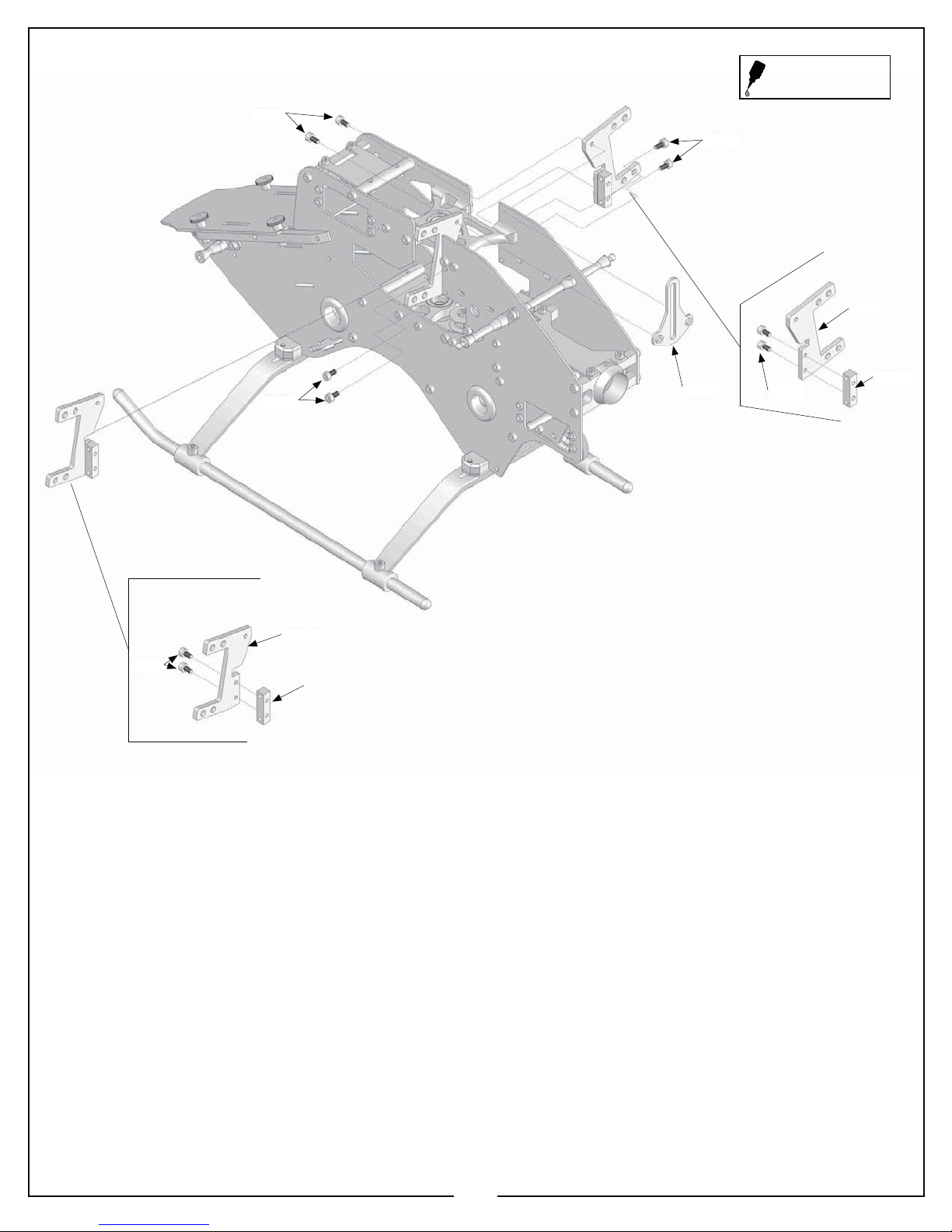
0060-1
0060-1
Apply a small amount of
medium thread lock when
threading into metal parts
129-22
0060-1
0060-1
129-19
0586-16
129-16
Illustration 1h
0060-1
2X
0586-16
In this step you will attach the left and right servo mount assemblies to the main frame assembly. Refer to Illustration 1h for this
step.
• Use two MA0060-1 m3x6 socket bolts to attach an MA0586-16 corner block from bag 1b to the MA129-19 c/f left servo
mount, and use two MA0060-1 m3x6 socket bolts to attach an MA0586-16 corner block from bag 1b to the MA129-22 c/f
right servo mount as shown.
• Use four MA0060-1 m3x6 socket bolts to attach the right and left servo mount assemblies to the inside of the main frame
assembly as shown.
17
 Loading...