

miniature aircraft MA1033, MA1033-1 Assembly Instructions Manual

s
A
e
s
b
m
y
l
n
I
t
s
u
r
t
c
o
i
s
n
Gas
Helicopter Kit
MA1033 Flybar
MA1033-1 Flybarless
Step up to excellence with X-Cell

Table of Contents
Kit Introduction .................................................................................................................................. 3
R/C Helicopter Safety ........................................................................................................................ 3
Warning ...................................................................................................................................................3
General Guidelines .................................................................................................................................
Academy of Model Aeronautics (AMA) ...........................................................................................4
Kit Assembly ...................................................................................................................................... 5
Required Tools ........................................................................................................................................5
Other Required Components ..................................................................................................................
Assembly Tips ................................................................................................................................... 6
Kit Contents ....................................................................................................................................... 7
Flybarless Head Assembly (Whiplash Kit #MA1033-1) .................................................................... 9
Flybarless Head Parts List ......................................................................................................................9
Flybarless Head Assembly Instructions ................................................................................................
Flybarless Head Link Lengths ...............................................................................................................
Flybar Head Assembly (Whiplash Kit #MA1033) ............................................................................ 12
Flybar Head Parts List ..........................................................................................................................12
Flybar Head Assembly Instructions .......................................................................................................
Flybar Head Link Lengths .....................................................................................................................
Tail Assembly ...................................................................................................................................17
Tail Assembly Parts List ........................................................................................................................17
Tail Assembly Instructions .....................................................................................................................
Gas Frame Assembly ...................................................................................................................... 23
Gas Frame Assembly Parts List ............................................................................................................23
Gas Frame Assembly Instructions ........................................................................................................
Electronics Mounting Positions .............................................................................................................
Canopy Mounting ..................................................................................................................................
Whiplash Gas User Guide............................................................................................................... 34
Safety ....................................................................................................................................................34
Engine/Fuel/Oil .....................................................................................................................................34
Fuel Tank Plumbing ...............................................................................................................................
Mufers .................................................................................................................................................35
Air Filter .................................................................................................................................................
Spark Plug ............................................................................................................................................
Electronic Wiring ...................................................................................................................................
Initial Mixture Settings ...........................................................................................................................
Throttle Setup/Curves ...........................................................................................................................
Governor Setup/Sensors ......................................................................................................................
Starting ..................................................................................................................................................36
Rotor Blades .........................................................................................................................................
Pitch Curves ..........................................................................................................................................
Gear Ratios ...........................................................................................................................................
Running .................................................................................................................................................37
Additional Support References .............................................................................................................
Kit Hardware and Parts ................................................................................................................... 38
Warranty Information ...................................................................................................................... 39
10
11
13
16
18
24
33
33
34
35
35
35
35
36
36
37
37
37
37
3
5
For updates to this manual, or any other Miniature Aircraft USA manual,
go to www.miniatureaircraftusa.com and follow the “Manuals” link.
2

Kit Introduction
Thank you for purchasing the X-Cell Whiplash by Miniature Aircraft USA. This model is the culmination of
years of designing and manufacturing R/C helicopters. It is designed with the highest standards, and will
provide years of enjoyment. Whether this is your rst R/C model helicopter or you are an advanced R/C
helicopter modeler, the X-Cell Whiplash is a fantastic choice for a “700 size” model.
R/C Helicopter Safety
A radio controlled model helicopter is not a toy, but rather a technically complex device that must be built
and operated with care. It is also a fascinating and challenging part of the R/C sport, the mastery of which
is very rewarding. A model helicopter must be built exactly in accordance with the building instructions. The
kit manufacturer has spent much time and effort rening his product to make it reliable in operation and easy
to build. The essentially bolt together construction can proceed quite rapidly, giving the builder a strong
sense of accomplishment that encourages hasty progress from one construction phase to the next, so that
the completed model can be more quickly seen and enjoyed. It is essential to recognize and guard against
this tendency. Follow building instructions exactly. Vibration and stress levels are high and all fasteners and
attachments must be secure for safe operation.
Note that this is the rst use of the word SAFETY in these comments. Previously the kit manufacturer’s efforts
to ensure reliable operation were mentioned. That is ALL that he can do. Safe operation is the responsibility
of the builder/yer and starts with careful construction and continues with selection and installation of reliable
radio equipment and engine.
The need for safety is nowhere greater than at the ying eld. A number of guidelines for safe ight have
been developed by experienced yers and are set down here. It is urged that they be read, understood and
followed.
Warning! – Risk of death or serious injury
Remote Control (“R/C”) Helicopters can be dangerous. Inexperienced pilots of R/C Helicopters should
be trained and supervised by experienced operators. All operators should use safety glasses and other
appropriate safety equipment. All operators should exercise necessary precautions when fueling, repairing,
maintaining, ying and storing R/C Helicopters, and when using or storing R/C Helicopter accessories,
equipment, fuels, and related materials. R/C Helicopters should be used only in open areas free of obstacles
and far enough from people to minimize the possibility of injury from the helicopter or any of its components
falling or ying in unexpected directions.
This helicopter is not a toy but a complex ying machine that must be assembled with care by a responsible
individual. Failure to exert care in assembly, or radio or accessory installation, may result in a model
incapable of safe ight or ground operation. Rotating components are an ever present danger and source of
injury to operators and spectators. Since the manufacturer and his agents have no control over the proper
assembly and operation of his products, no responsibility or liability can be assumed for their use.
General Guidelines for Safe R/C Helicopter Flight
• Fly only at approved ying elds and obey eld regulations.
• Follow frequency control procedures. Interference can be dangerous to all.
• Know your radio. Check all transmitter functions before each ight.
• Be aware that rotating blades are very dangerous and can cause serious injury.
• Never y near or above spectators or other modelers.
• If you’re a beginner, get help trimming the model rst and ight training later.
• Don’t “track” the main blades by holding the tail boom. This is a temptation to builders who cannot hover
yet and is very dangerous.
• Follow all recommended maintenance procedures for model, radio and engine.
3

Academy of Model Aeronautics
Miniature Aircraft USA highly recommends joining the Academy of Model Aeronautics (AMA).
• AMA is the Academy of Model Aeronautics.
• AMA is the world’s largest model aviation association, representing a membership of more than 150,000
from every walk of life, income level and age group.
• AMA is a self-supporting, non-prot organization whose purpose is to promote development of model
aviation as a recognized sport and worthwhile recreation activity.
• AMA is an organization open to anyone interested in model aviation.
• AMA is the ofcial national body for model aviation in the United States. AMA sanctions more than a
thousand model competitions throughout the country each year and certies ofcial model ying records
on a national and international level.
• AMA is the organizer of the annual National Aeromodeling Championships, the world’s largest model
airplane competition.
• AMA is the chartering organization for more than 2,500 model airplane clubs across the country. AMA
offers its chartered clubs ofcial contest sanction, insurance and assistance in getting and keeping ying
sites.
• AMA is the voice of its membership, providing liaison with the Federal Aviation Administration, the Federal
Communications Commission, and other government agencies through our national headquarters in
Muncie, Indiana. AMA also works with local governments, zoning boards and parks departments to
promote the interests of local chartered clubs.
• AMA is an associate member of the National Aeronautic Association. Through NAA, AMA is recognized by
the Fédération Aéronautique Internationale (FAI), the world governing body of all aviation activity, as the
only organization which may direct U.S. participation in international aeromodeling activities.
For more detailed information, contact the Academy of Model Aeronautics
5161 E. Memorial Drive, Muncie, Indiana, 47302
or telephone (800) 435-9262.
You may also visit the AMA website at www.modelaircraft.org
4

Kit Assembly
Your Whiplash kit will require a number of different supplies and tools to ensure the best nal result. They
are as follows:
Required Lubricants and Compounds:
1. Medium Strength Thread Locking Compound - X-Cell Super Lock Blue (MA3200-20)
2. Tri-Flow Oil (MA3200-02)
3. MA Synthetic Hydrocarbon Grease (MA3200-10)
4. Medium Cyanoacrylate (CA)
5. Retaining Compound - X-Cell Super Lock Green (MA3200-22)
Required Tools:
1. m4 Nut Driver
2. m5 Nut Driver
3. m5.5 Nut Driver
4. m7 Nut Driver
5. 1.5mm Allen Driver
6. 2.0mm Allen Driver
7. 2.5mm Allen Driver
8. 3.0mm Allen Driver
9. 4.0mm Allen Driver x2
10. 5.0mm Allen Driver
11. Needle Nose Pliers
12. Phillips Screwdriver
13. Razor Knife (X-acto)
Other required components:
The X-Cell Whiplash is an airframe kit. To complete the model, several other items are required but are not
included with the kit. There are many choices for these other required components, and any competent
hobby retailer with R/C helicopter experience will be happy to make suggestions. You will need:
1. Engine, 23-29cc R/C format gas engine
2. Helicopter style mufer suited to the engine you choose.
3. Cyclic servos (Miniature Aircraft USA recommends high quality digital cyclic servos with no less than
80 oz. in. of torque.)
4. Throttle servo (Miniature Aircraft USA recommends a high quality ball bearing sevro)
4. R/C helicopter gyro (Miniature Aircraft USA recommends for Flybarless Kits a ybarless electronic
unit with rudder gyro and for Flybar Kits only a tail “heading hold” style gyro is needed)
5. Rudder servo suitable for use with the gyro you choose. Digital servo is recommended.
6. R/C helicopter transmitter and receiver with at least 6 channels, and eCCPM capabilities.
7. 690-710mm Main Blades and 105mm Tail Blades
8. R/C helicopter starting and fueling equipment compatible with gasoline fuel
9. R/C helicopter engine governor is recommended
Refer to the “Whiplash Gas User Guide” on page 34 of this manual for more information on
recommended equipment and setup.
5

Important Assembly Tips - PLEASE READ
• Follow the instructions. The methods of construction documented in this manual have been proven to
work. Do not rush the build of your model! You have purchased a world class model helicopter kit, take
your time and realize that the nal result is now up to you. Take the time to fully understand each step and
if you are unsure please contact Miniature Aircraft USA.
• Follow the order of assembly. The instructions have been organized into major sections and have been
written in such a way that each step builds upon the work done in the previous step. Changing the order of
assembly may result in unnecessary steps.
• Clean all metal parts. All of the steel parts in this kit are coated with a lubricant to prevent them from
rusting. This coating can interfere with the adhesives and thread locks needed for assembly. Use a solvent
such as alcohol or acetone to clean the various metal parts, especially threads. Be sure not to overtighten
bolts as damage to bearings and other components will occur.
• It is very important to lightly sand the edges of all carbon ber pieces. Miniature Aircraft USA recommends
doing so prior to the assembly process. Carbon ber edges are sharp and can easily cut component wires
and battery mounting straps. It is important to use safety precautions when creating carbon ber dust.
The use of a particulate mask, preferably one with a P100 HEPA lter is recommended. Always clean up
carbon ber dust with a damp rag right away.
• Use thread lock as indicated. Generally any bolt or screw that threads into a metal part requires thread
lock. Model helicopters are subject to vibration and failing to use thread lock on any non-locking assembly
may result in a part becoming loose or falling off.
6

Kit Contents
Please take some time to familiarize yourself with the contents of the kit. The Whiplash kit has been broken down into
three “bags”. Each bag contains parts and hardware. The hardware for each bag will be used only for that bag. There
will be no left over parts after each bag is assembled. The individual parts of the factory assembled parts are not listed
out here. They can be found in the components section of the manual.
Bag 1 - Flybarless Kits (MA1033-1)
Bag Part No. Part Description Qty
1-A 0869 Washout Link 2
1-A 128-176 Washout Pin 2
1-A 128-195 Head Button 1
1-A 128-314 Swashplate Follower 2
1-A 131-187 Head Axle 1
1-A 131-190 Damper (80D) 2
1-A 131-368 FBL Head Block 1
1-B 0133-1 M3x21.5 Ball Link 10
1-B 0217 Swashplate 1
1-B 121-4 Servo To Swash Linkage Rod 3
1-B 121-7 Swash To PA Linkage Rod 2
1-B 131-308 FBL Main Shaft 1
1-C 131-161 Main Blade Grip 2
1-C 131-163 FBL Pitch Arm 2
Bag 1 - Flybar Kits (MA10333)
Bag Part No. Part Description Qty
1-A 0133-1 M3x21.2 Ball Link 4
1-A 121-4 Servo To Swash Rod 2
1-A 128-189 Cage Bar 2
1-A 128-195 Head Button 1
1-A 131-155 Cage End 2
1-A 131-168 FB Head Block 1
1-A 131-187 Head Axle 1
1-A 131-190 Damper (80D) 2
1-B 120-7 5x15 C/F Safety Washer 2
1-B 128-196 Alumimum Bell Mixer 2
1-B 131-161 Main Blade Grip 2
1-B 131-162 FB Pitch Arm 2
1-B 131-184 9x14x.080 C/F Damper Washer 2
1-C 0217 Swashplate 1
1-C 0219 Washout Center Hub 1
1-C 0869 Washout Link 2
1-C 106-05 Washout Arm 2
1-C 128-176 Washout Pin 2
1-C 131-8 FB Main Shaft 1
1-D 0133 M2x21.2 Ball Link 2
1-D 0133-1 M3x21.2 Ball Link 10
1-D 0135 M2x16.4 Ball Link 2
Bag Part No. Part Description Qty
1-Hardware 0021 M4 Lock Nut 1
1-Hardware 0023 M5 Nut 2
1-Hardware 0051 M3x3 Set Screw 3
1-Hardware 0061 M3x8 Socket Bolt 4
1-Hardware 0063 M3x10 Socket Bolt 2
1-Hardware 0064-4 M3x16 Button Head Socket Bolt 2
1-Hardware 0067 M3x14 Socket Bolt 1
1-Hardware 0082-4 M5x32 Shouldered Socket Bolt 2
1-Hardware 0086-1 M5x16 Flanged Socket Bolt 2
1-Hardware 0107 M3x6 Threaded Steel Ball 5
1-Hardware 0109 M3x8 Threaded Steel Ball 4
1-Hardware 0447-1 M2 E-clip 2
1-Hardware 120-7 5x15 C/F Safety Washer 2
1-Hardware 131-83 Anti-rotation Pin 1
1-Hardware 131-184 C/F Damper Washer 2
1-Hardware 131-200 M4x33 Shouldered Socket Bolt 1
Bag Part No. Part Description Qty
1-D 0313 M2x10 Threaded Control Rod 2
1-D 120-25 Swash To Mixer Linkage Rod 2
1-D 121-4 Servo To Swash Linkage Rod 3
BOX 0303 Flybar 1
1-Hardware 0021 M4 Lock Nut 1
1-Hardware 0023 M5 Nut 2
1-Hardware 0050-1 M2.5 Set Screw 2
1-Hardware 0051 M3x3 Set Screw 3
1-Hardware 0057 M4x4 Set Screw 2
1-Hardware 0061 M3x8 Socket Bolt 4
1-Hardware 0063 M3x10 Socket Bolt 2
1-Hardware 0064-3 M3x6 Button Head Socket Bolt 4
1-Hardware 0067 M3x14 Socket Bolt 3
1-Hardware 0071 M3x18 Socket Bolt 2
1-Hardware 0082-4 M5x32 Shouldered Socket Bolt 2
1-Hardware 0086-1 M5x16 Flanged Socket Bolt 2
1-Hardware 0107 M3x6 Threaded Steel Ball 5
1-Hardware 0109 M3x8 Threaded Steel Ball 6
1-Hardware 0112 M3x9.5 Threaded Steel Ball 4
1-Hardware 0447-1 M2 E Clip 2
1-Hardware 131-83 Anti Rotation Pin 1
1-Hardware 131-200 M4x33 Shouldered Socket Bolt 1
7

Bag 2 - Tail Assembly
Bag Part No. Part Description Qty
Bag Part No. Part Description Qty
2-A 0133 M2x21.2 Ball Link 2
2-A 128-144 T/R Control Rod Guide 4
2-A 131-57 Torque Tube Ends 2
2-A 131-58 Torque Tube 1
2-A 131-62 Tail Boom 1
2-A 131-69-1 T/R Control Rod 1
2-A 131-80 Torque Tube Bearing Cup 2
2-A 131-81 Torque Tube Bearing Cup O-ring 4
2-A 131-86 Assembled Boom Support 2
2-B 131-34 Front Tail Transmission 1
2-B 131-35 Boom Clamp W/TX Holes 1
2-B 131-64 T/R Hub 1
2-B 131-75 T/R Pitch Slider Assembly 1
2-B 131-112 T/R Blade Grip 2
2-B 131-129 Tail Box 1
2-B 131-130 Tail Pitch Control Bellcrank 1
2-B 131-131 C/F Bellcrank Bracket 1
2-B 131-132 Bellcrank Slider Cup 1
Bag Part No. Part Description Qty
3-A 131-29 C/F X-Brace 1
3-A 131-47 C/F Servo Rail Spacer 2
3-A 131-53 C/F Gyro Plate 1
3-A 131-55 C/F Angled Battery Tray 1
3-A 131-148 C/F Servo Plates 14
3-A 131-153 C/F Canopy Breakaway Tabs 4
3-A 131-186 C/F Anti-rotation Bracket 1
3-A 133-94 C/F Fuel Tank Plate 1
3-A 133-107 C/F Front Doubler - Gas 2
3-A 133-108 C/F Rear Doubler - Gas 2
3-A 133-110 C/F Bottom Plate - Gas 1
3-A 133-117 C/F Left Frame - Gas 1
3-A 133-118 C/F Right Frame - Gas 1
3-B 128-57 Tray Mount 3
3-B 128-58 Frame Spacer 3
3-B 131-20 Mid Main Bearing Block 1
3-B 131-21 Upper Main Bearing Block 1
3-B 131-40 Lower Main Bearing Block 1
3-B 131-46 P/A Servo Rail 2
3-B 131-52 Delrin Tray Mount 2
3-C 0818-3 Mounting Block 2
3-C 128-57 Tray Mount 3
3-C 128-118 6mm Hex Adaptor 1
3-C 131-3 Start Shaft w/Sleeve (128-108) 1
3-C 131-179 Nitro X-Block 1
3-C 133-9 Assembled Gas Clutch Bell 1
3-C 133-18 18T Pinion w/Sleeve 1
3-C 133-119 Flanged Clutch Spacer 2
3-C 133-120 One Way Bearing Bracket 1
3-C 133-121 Motor Mount 1
3-D 0133-1 M3x21.2 Ball Link 2
3-D 0390 Wire Retainers 3
3-D 106-22 Rubber Canopy Grommet 4
3-D 121-6 M3x75 Threaded Control Rod 1
3-D 128-59 M4 Front Boom Support Brace 1
3-D 131-1 124T Main Gear 1
3-D 131-24 Main Gear Hub 1
3-D 131-50 Elevator Servo Mount 2
3-D 131-136 Struts 4
3-D 131-150 Front Canopy Post 2
3-D 131-151 Rear Canopy Post 2
3-D 131-154 Thumb Screw 4
3-D 133-135 Landing Gear Post 2
3-D 3200-48 3/4” Hook and Loop Tape 15”
2-C 128-80 Front Boom Clamp 1
2-C 128-149a Upper Rear Boom Support Mount 1
2-C 128-149b Lower Rear Boom Support Mount 1
2-C 131-60 C/F Tail Fin 1
2-C 131-128 C/F Boom Clamp Plate 1
2-Hardware 0009 M3 Washer 2
2-Hardware 0016-1 M4 External Serrated Lock Washer 2
2-Hardware 0019 M3 Lock Nut 3
2-Hardware 0056 M3x5 Dog-Point Set Screw 2
2-Hardware 0059-0 M2.5x4 Socket Bolt 6
2-Hardware 0059-1 M2.5x6 Socket Bolt 1
2-Hardware 0060-1 M3x6 Socket Bolt 4
2-Hardware 0061 M3x8 Socket Bolt 3
2-Hardware 0064-3 M3x6 Button Head Socket Bolt 2
2-Hardware 0065 M3x12 Socket Bolt 6
2-Hardware 0067 M3x14 Socket Bolt 2
2-Hardware 0069 M3x16 Socket Bolt 2
2-Hardware 0073 M3x20 Socket Bolt 1
2-Hardware 0078 M4x12 Socket Bolt 2
2-Hardware 0107 M3x6 Threaded Steel Ball 4
Bag 3 - Gas Frame Assembly
Bag Part No. Part Description Qty
3-E 0405 Fuel Pick up 1
3-E 0409 90 Degree Nipple 1
3-E 105-100 High Flex Fuel Line 24”
3-E 128-90 Tank Mounting Studs 2
3-E 128-92 Fuel Tank Plug 1
3-E 131-144 Rubber Fuel Tank Mount 4
3-E 133-99 Whiplash Gas Fuel Tank 1
3-E 133-140 Fuel Nipple 1
3-Hardware 0004 M4 Washer 1
3-Hardware 0003 3mm Washer 12
3-Hardware 0011 5mm Washer 1
3-Hardware 0011-4 5x15x.08 Washer 1
3-Hardware 0013 5mm Hex Nut 1
3-Hardware 0014F 5mm Hex Nut - Fine Thread 1
3-Hardware 0015 2mm Hex Nut 1
3-Hardware 0016-1 M4 External Serrated Lock Washer 2
3-Hardware 0017-2 2.5mm Hex Nut 5
3-Hardware 0021 M4 Lock Nut 1
3-Hardware 0032 M3 Self Tapping Screw 8
3-Hardware 0057 M4x4 Set Screw 6
3-Hardware 0059-1 M2.5x6 Socket Bolt 4
3-Hardware 0059-3 M2.5x10 Socket bolt 16
3-Hardware 0059-7 M2.5x20 Socket Bolt 4
3-Hardware 0060-1 M3x6 Socket Bolt 20
3-Hardware 0061 M3x8 Socket Bolt 48
3-Hardware 0063 M3x10 Socket Bolt 12
3-Hardware 0064-3 M3x6 Button Head 6
3-Hardware 0065 M3x12 Socket Bolt 4
3-Hardware 0081 M4x16 Socket Bolt 6
3-Hardware 0085 M5x16 Socket Bolt 4
3-Hardware 0088 M3x8 Tapered Socket Bolt 5
3-Hardware 0103 M2 Threaded Steel Ball 1
3-Hardware 0116 M2.5 Threaded Steel Ball 5
3-Hardware 131-201 M4x25 Shouldered Socket Bolt 1
BOX 131-139 Skids 2
BOX 131-152 Whiplash Canopy 1
BOX 133-230 Whiplash Gas Instruction Manual 1
BOX 3000-73 MA Towel 1
8
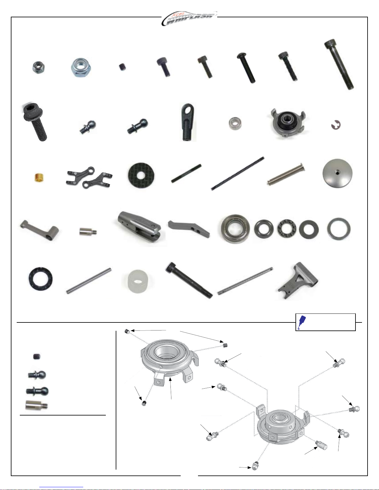
MA1033-1 - Flybarless Head Assembly Parts
0021
M4 Hex Locknut
0086-1
M5x16 Flanged Bolt
0597-4
M3x4.75x.215 Brass
Spacer
128-314
Swashplate Follower
0023
M5 Hex Locknut
0107
M3x6 Threaded Steel
Ball
0869
3D Washout Link
131-83
Swashplate Pin
0051
M3x3 Socket Set
Screw
0109
M3x8 Threaded Steel
Ball
120-7
M5x15 Carbon Fiber
Safety Washer
131-161
Aluminum Blade Grip
0061
M3x8 Socket Bolt
M3x21.2 Ball Link
M3x30 Threaded
Control Rod
Aluminum Pitch Arm
M3x10 Socket Bolt
0133-1
121-4
131-163
0063
0064-4
M3x16 Button Head
Socket Bolt
0159
3x7x3 Bearing
121-7
M3x65 Threaded
Control Rod
131-181
9x17x5 Bearing
0067
M3x14 Socket Bolt
0217
Swashplate
128-176
M2x.584 Washout
Pivot Pin
131-182
9x17x5 Thrust Bearing
0082-4
M5x32 Shouldered
Socket Bolt
0447-1
E-Clip
128-195
Aluminum Head Button
131-183
9x14x.75 Washer
131-184
Carbon Fiber Damper
Washer
131-187
Head Axle
Damper (80D)
Hardware for
this assembly
0051 x 3
M3x3 Socket Set
Screw
0107 x 3
M3x6 Threaded
Steel Ball
0109 x 4
M3x8 Threaded Steel
Ball
131-83 x 1
Swashplate Pin
Assembly Tip
• Install MA0051 M3x3 Socket Set
Screws only until they bottom out
against the lower bearing. Do not
overtighten or damage to swashplate
bearing will occur. Note: these are
used to adjust the bearing tolerance if
it develops play over time.
131-190
0051
131-200
M4x33 Shouldered
Socket Bolt
0051
0107
0217
9
0109
131-308
Flybarless Main Shaft
0109
0107
131-368
Flybarless Head Block
Apply a small amount of
medium thread lock when
threading into metal parts
131-83
0109
0107
0109
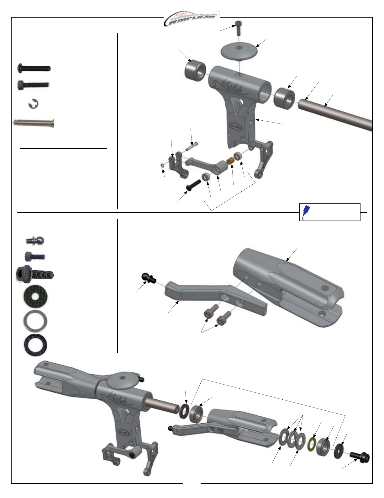
Hardware for
this assembly
131-190
0067
128-195
0064-4 x 2
M3x16 Button Head
Socket Bolt
0067 x 1
M3x14 Socket Bolt
0447-1 x 2
E-clip
128-176 x 2
M2x.584 Washout
Pivot Pin
Assembly Tip
• The use of a light grease such as
MA3200-06 Tri-Flow Synthetic Grease
is required for damper/head axle
lubrication
Hardware for
this assembly
0107 x 2
M3x6 Threaded
Steel Ball
0061 x 4
M3x8 Socket Head
Cap Screw
0086-1 x 2
M5x16 Flanged Bolt
0869
0447-1
0064-4
128-176
X2
0159
X2
0597-4
128-314
0159
Factory Installed
131-190
131-368
131-161
Apply
grease to
Head Axle
131-187
Apply a small amount of
medium thread lock when
threading into metal parts
120-7 x 2
M5x15 Carbon Fiber
Safety Washer
131-183 x 2
9x14x.75 Washer
131-184 x 2
Carbon Fiber Damper
Washer
Assembly Tips
• The use of a light grease
such as MA3200-06 Tri-Flow
Synthetic Grease is required
for thrust bearing lubrication
(pre-applied and assembled
from factory)
• 3 piece thrust bearing
(MA131-182) outer race with
larger I.D. (inside diameter)
installs closest to hub.
0107
131-163
131-184
10
0061
131-181
Bearings Factory Installed
in Blade Grips
131-182
Large
Small
I.D.
I.D.
131-183
131-181
120-7
0086-1
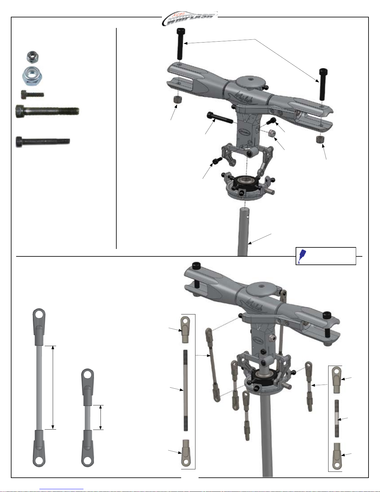
Hardware for
this assembly
0021 x 1
M4 Hex Locknut
0023 x 2
M5 Hex Locknut
0063 x 2
M3x10 Socket Bolt
0082-4
0082-4 x 2
M5x32 Shouldered
Socket Bolt
131-200 x 1
M4x33 Shouldered
Socket Bolt
Link Arm
Lengths and
Installation
0023
131-200
0063
131-308
0063
0021
0023
Apply a small amount of
medium thread lock when
threading into metal parts
X2
47.5mm
X3
13.5mm
0133-1
121-7
0133-1
0133-1
121-4
0133-1
11
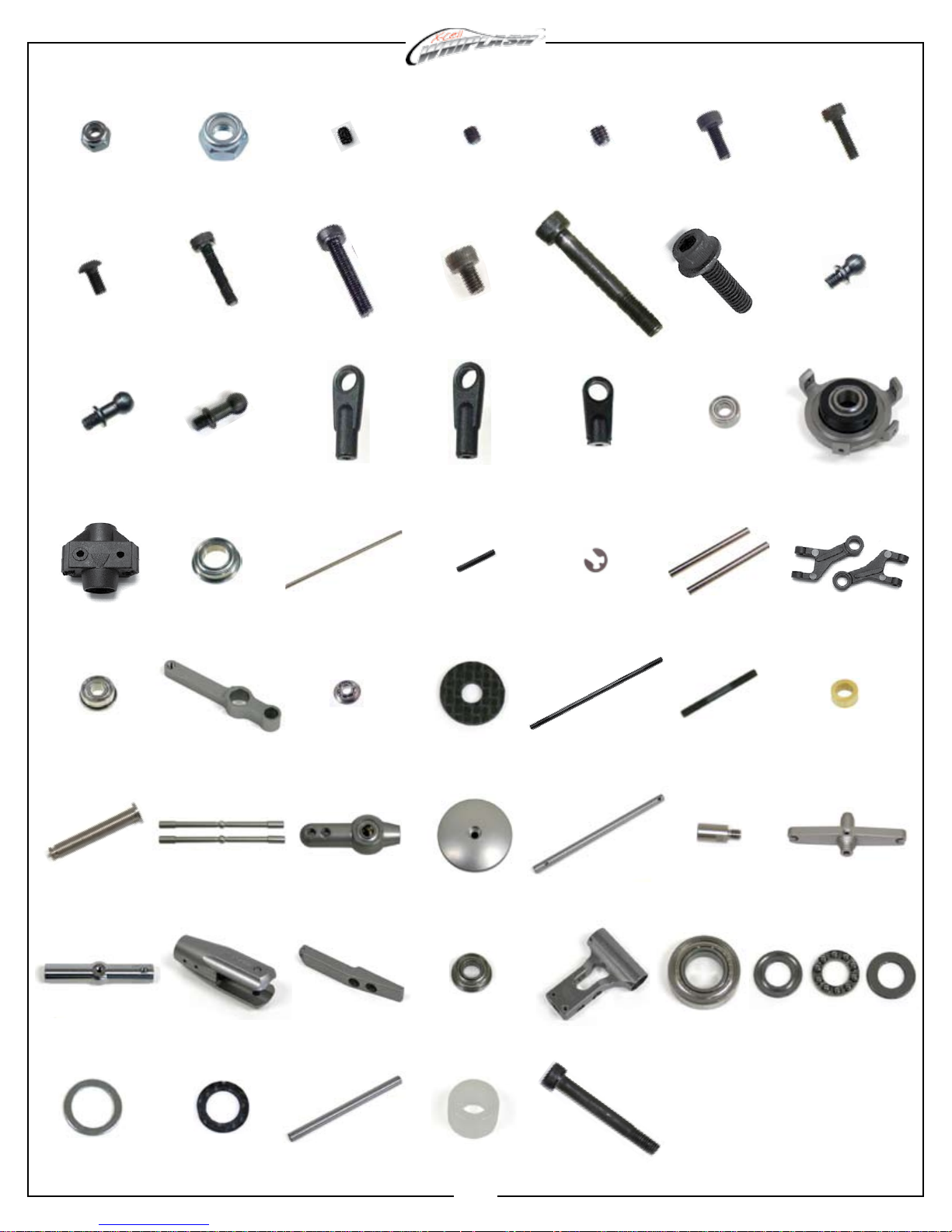
MA1033 - Flybar Head Assembly Parts
0021
M4 Hex Locknut
0064-3
M3x6 Button Head
Socket Bolt
M3x8 Threaded Steel Ball
0109
0219
Washout Center Hub
0023
M5 Hex Locknut
0067
M3x14 Socket Bolt
0112
M3x9.5 Threaded Steel
6x10x3 Flanged Bearing
Ball
0283
0050-1
M2.5x3 Socket Set
Screw
0071
M3x18 Socket Bolt
0133
M2x21.2 Plastic
Ball Link
0303
M4x17.75” Flybar
0051
M3x3 Socket Set
Screw
0078-3
M4x6 Socket Bolt
0133-1
M3x21.2 Plastic
Ball Link
0313
M2x10 Threaded
Control Rod
0057
M4x4 Socket Set
Screw
0082-4
M5x32 Shouldered
Socket Bolt
0135
M2x16.4 Plastic
Ball Link
0447-1
E-clip
0061
M3x8 Socket Bolt
0086-1
M5x16 Flanged Bolt
0159
3x7x3 Bearing
0840-27
Washout Head Pin
0063
M3x10 Socket Bolt
M3x6 Threaded Steel Ball
0107
0217
Swashplate
0869
3D Washout Link
106-02
3x7x3 Flanged Bearing
128-176
M2x.584 Washout Pivot
Pin
131-157
Flybar Cross Tube
131-183
9x14x.75 Washer
106-05
Aluminum Washout Arm
128-189
Flybar Control Bar
131-161
Aluminum Blade Grip
131-184
Carbon Fiber Damper
Washer
2x5x.5 Flanged Bearing
Aluminum Bell Mixer
Flybar Pitch Arm
106-06
128-196
131-162
131-187
Head Axle
120-7
M5x15 Carbon Fiber
Safety Washer
128-195
Aluminum Head Button
131-166
4x8x3 Flanged Bearing
131-190
Damper (80D)
12
120-25
M2.6x86 Threaded
Control Rod
131-8
Flybar Main Shaft
131-168
Flybar Head Block
131-200
M4x33 Shouldered
Socket Bolt
121-4
M3x30 Threaded Control
Rod
131-83
Swashplate Pin
131-181
9x17x5 Bearing
122-28
M3x.125”x.79” Brass
Spacer
131-155
Flybar Cage End
131-182
9x17x5 Thrust Bearing
 Loading...