

Page 1
Online Edition for Part no. 01 40 2 904 077 - © 03/12 BMW AG
Contents
OWNER'S MANUAL
MINI COUPE
MINI ROADSTER
MINI CONVERTIBLE
A - Z
Page 2

Cooper
Online Edition for Part no. 01 40 2 904 077 - © 03/12 BMW AG
Cooper S
John Cooper
Works
Congratulations on your new MINI
This Owner’s Manual should be considered a permanent part of
this vehicle. It should stay with the vehicle when sold to provide
the next owner with important operating, safety and maintenance information.
We wish you an enjoyable driving experience.
Page 3

© 2012 Bayerische Motoren Werke
Online Edition for Part no. 01 40 2 904 077 - © 03/12 BMW AG
Aktiengesellschaft
Munich, Germany
Reprinting, including excerpts, only with the
written consent of BMW AG, Munich.
US English II/12, 03 12 500
Printed on environmentally friendly paper,
bleached without chlorine, suitable for recycling.
Page 4

Contents
Online Edition for Part no. 01 40 2 904 077 - © 03/12 BMW AG
The fastest way to find information on a particular topic or item is by using the index, refer to
page 268.
4 Notes
6 Reporting safety defects
AT A GLANCE 9
10 Cockpit
17 Onboard computer
22 Letters and numbers
23 Voice activation system
CONTROLS 27
28 Opening and closing
50 Adjustments
56 Transporting children safely
60 Driving
70 Controls overview
82 Technology for driving comfort and safety
96 Lamps
101 Climate
107 Practical interior accessories
COMMUNICATIONS 169
170 Hands-free device Bluetooth
180 Mobile phone preparation Bluetooth
193 Office
201 MINI Connected
MOBILITY 205
206 Refueling
209 Wheels and tires
221 Engine compartment
225 Maintenance
227 Care
231 Replacing components
243 Giving and receiving assistance
REFERENCE 249
250 Technical data
260 Short commands for the voice activation
system
268 Everything from A to Z
DRIVING TIPS 113
114 Things to remember when driving
NAVIGATION 123
124 Navigation system
126 Destination entry
135 Route guidance
143 What to do if…
ENTERTAINMENT 145
146 On/off and tone
149 Radio
157 CD player
159 External devices
Page 5

Notes
Online Edition for Part no. 01 40 2 904 077 - © 03/12 BMW AG
Notes
Using this Owner's Manual
We have tried to make all the information in this
Owner's Manual easy to find. The fastest way to
find specific topics is to refer to the detailed
index at the back of the manual. If you wish to
gain an initial overview of your vehicle, you will
find this in the first chapter.
Should you wish to sell your MINI at some time in
the future, remember to hand over this Owner's
Manual to the new owner; it is an important part
of the vehicle.
Additional sources of information
Should you have any other questions, your MINI
dealer will be glad to advise you at any time.
You can find more information about the MINI,
for example on its technology, on the Internet at
www.MINI.com.
Symbols used
Indicates precautions that must be followed precisely in order to avoid the pos-
sibility of personal injury and serious damage to
the vehicle.<
Indicates information that will assist you in
gaining the optimum benefit from your
vehicle and enable you to care more effectively
for your vehicle.<
Refers to measures that can be taken to
help protect the environment.<
< Marks the end of a specific item of
information.
"..." Identifies Control Display texts used to
select individual functions.
{...} Verbal instructions to use with the voice
activation system.
{{...}} Identifies the answers generated by the
voice activation system.
Symbols on vehicle components
Indicates that you should consult the relevant section of this Owner's Manual for
information on a particular part or assembly.
Vehicle equipment
The manufacturer of your MINI is the Bayerische
Motoren Werke Aktiengesellschaft, BMW AG.
This Owner's Manual describes all models as well
as all production, country and special equipment that is offered in the model range. Equipment is also described that is not available
because of, for example, selected options or
country version. This also applies to safety
related functions and systems. For equipment
and models that are not described in this
Owner's Manual, please see the supplementary
Owner's Manuals that are provided.
Status of this Owner's Manual at time of printing
The high level of safety and quality of the MINI
vehicles is ensured through continuous development. In rare cases, there may be differences
between the description and the vehicle.
4
Page 6

Notes
Online Edition for Part no. 01 40 2 904 077 - © 03/12 BMW AG
For your safety
Maintenance and repair
Advanced technology, e.g. the use of
modern materials and high-performance
electronics, requires specially adapted maintenance and repair methods. Therefore, have the
necessary work on your MINI only carried out by
a MINI dealer or a workshop that has specially
trained personnel working in accordance with
the specifications of the MINI manufacturer. If
this work is not carried out properly, there is a
danger of subsequent damage and related
safety hazards.<
Parts and accessories
For your own safety, use genuine parts
and accessories approved by the manufacturer of the MINI.
When you purchase accessories tested
and approved by the manufacturer of the MINI
and Original MINI Parts, you simultaneously
acquire the assurance that they have been thoroughly tested by the manufacturer of the MINI
to ensure optimum performance when installed
on your vehicle.
The manufacturer of the MINI warrants these
parts to be free from defects in material and
workmanship.
The manufacturer of the MINI will not accept any
liability for damage resulting from installation of
parts and accessories not approved by the manufacturer of the MINI.
The manufacturer of the MINI cannot test every
product made by other manufacturers to verify
if it can be used on a MINI safely and without
risk to either the vehicle, its operation, or its
occupants.
Original MINI Parts, MINI Accessories and other
products approved by the manufacturer of the
MINI, together with professional advice on using
these items, are available from all MINI dealers.
Installation and operation of accessories that
have not been approved by the manufacturer of
your MINI, such as alarms, radios, amplifiers,
radar detectors, wheels, suspension components, brake dust shields, telephones, including
operation of any mobile phone from within the
vehicle without using an externally mounted
antenna, or transceiver equipment, for instance,
CBs, walkie-talkies, ham radios or similar accessories, may cause extensive damage to the vehicle, compromise its safety, interfere with the
vehicle's electrical sys te m o r a ff ec t t he va lidi ty of
the MINI Limited Warranty. See your MINI dealer
for additional information.<
Maintenance, replacement, or repair of
the emission control devices and systems
may be performed by any automotive repair
establishment or individual using any certified
automotive part.<
California Proposition 65 warning
California law requires us to issue the following
warning:
Engine exhaust and a wide variety of
automobile components and parts,
including components found in the interior furnishings in a vehicle, contain or emit chemicals
known to the State of California to cause cancer
and birth defects and reproductive harm. In
addition, certain fluids contained in vehicles
and certain products of component wear contain or emit chemicals known to the State of
California to cause cancer and birth defects or
other reproductive harm.
Battery posts, terminals and related accessories
contain lead and lead compounds. Wash your
hands after handling.
Used engine oil contains chemicals that have
caused cancer in laboratory animals. Always
protect your skin by washing thoroughly with
soap and water.<
5
Page 7

Notes
Online Edition for Part no. 01 40 2 904 077 - © 03/12 BMW AG
Service and warranty
We recommend that you read this publication
thoroughly.
Your MINI is covered by the following
warranties:
> New Vehicle Limited Warranty
> Rust Perforation Limited Warranty
> Federal Emissions System Defect Warranty
> Federal Emissions Performance Warranty
> California Emission Control System Limited
Warranty
Detailed information about these warranties is
listed in the Service and Warranty Information
Booklet for US models or in the Warranty and
Service Guide Booklet for Canadian models.
Your vehicle has been specifically adapted and
designed to meet the particular operating conditions and registration requirements in your
country and continental region in order to
deliver the full driving pleasure while the vehicle
is operated under those conditions. If you wish
to operate your vehicle in another country or
region, you may be required to adapt your
vehicle to meet different prevailing operating
conditions and registration requirements. You
should also be aware of any applicable warranty
limitations or exclusions for such country or
region. In such a case, please contact Customer
Relations for further information.
Maintenance
Maintain the vehicle regularly to sustain road
safety, operational reliability and the New
Vehicle Limited Warranty.
Specifications for required maintenance
measures:
> MINI Maintenance System
> Service and Warranty Information Booklet
for US models
> Warranty and Service Guide Booklet for
Canadian models
If the vehicle is not maintained according to
these specifications, this could result in serious
damage to the vehicle. Such damage is not covered by the MINI New Vehicle Limited Warranty.
Reporting safety defects
For US customers
The following applies only to vehicles owned
and operated in the US.
If you believe that your vehicle has a defect that
could cause a crash or could cause injury or
death, you should immediately inform the
National Highway Traffic Safety Administration,
NHTSA, in addition to notifying MINI of North
America, LLC, P.O. Box 1227, Westwood, New
Jersey 07675-1227, Telephone 1-800-831-
1117.
If NHTSA receives similar complaints, it may
open an investigation, and if it finds that a safety
defect exists in a group of vehicles, it may order
a recall and remedy campaign. However, NHTSA
cannot become involved in individual problems
between you, your dealer, or MINI of North
America, LLC.
To contact NHTSA, you may call the Vehicle
Safety Hotline toll-free at 1-888-327-4236 (TTY:
1-800-424-9153); go to http://www.safercar.gov; or write to: Administrator, NHTSA, 400
Seventh Street, SW., Washington, DC 20590. You
can also obtain other information about motor
vehicle safety from http://www.safercar.gov
For Canadian customers
Canadian customers who wish to report a
safety-related defect to Transport Canada,
Defect Investigations and Recalls, may telephone the toll-free hotline 1-800-333-0510.
You can also obtain other information about
motor vehicle safety from http://www.tc.gc.ca/
roadsafety
6
Page 8

Notes
Online Edition for Part no. 01 40 2 904 077 - © 03/12 BMW AG
7
Page 9

Watch Me.
Online Edition for Part no. 01 40 2 904 077 - © 03/12 BMW AG
Page 10

AT A GLANCE
Online Edition for Part no. 01 40 2 904 077 - © 03/12 BMW AG
CONTROLS
DRIVING TIPS
NAVIGATION
ENTERTAINMENT
COMMUNICATIONS
MOBILITY
REFERENCE
Page 11

AT A GLANCE Cockpit
Online Edition for Part no. 01 40 2 904 077 - © 03/12 BMW AG
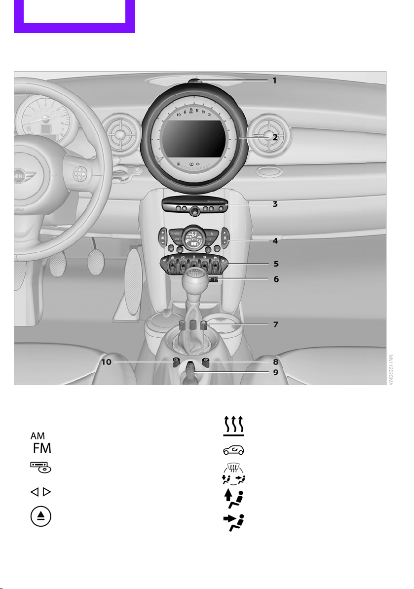
Cockpit
Vehicle equipment
In this chapter, all production, country, and
optional equipment that is offered in the model
Around the steering wheel
range is described. Equipment is also described
that is not available because of, for example,
selected options or country version. This also
applies to safety related functions and systems.
10
Page 12
Cockpit AT A GLANCE
Online Edition for Part no. 01 40 2 904 077 - © 03/12 BMW AG
1 Adjusting the exterior mirrors, folding them
in and out 54
2
Parking lamps 96
Low beams 96
Automatic headlamp control 96
Adaptive Light Control 97
Turn signals 65
High beams 98
Headlamp flasher 65
Roadside parking lamps 98
Computer 71
3 MINI Roadster, MINI Convertible: Always
Open Timer 72
4 Tachometer 12
Instrument lighting 99
Resetting the trip odometer 71
5
6
Wiper system 66
Switching the ignition on/off and
starting/stopping the engine 60
7 Ignition lock 60
8 Buttons on steering wheel,
Right side
Resuming cruise control 68
Storing speed and accelerating or
decelerating
or
Activating/deactivating cruise
control 68
Left side
Increasing or reducing volume
Telephone:
Press: accepting and ending a call,
starting dialing of selected phone
number and redialing if no phone
number is selected
Microphone on steering column
Activating/deactivating voice
activation system 23
Microphone on steering column
Changing the radio station
Selecting a music track
Scrolling through the redial list
9 Horn: the entire surface
10 Adjusting the steering wheel 55
11 Releasing the hood 222
11
Page 13
AT A GLANCE Cockpit
Online Edition for Part no. 01 40 2 904 077 - © 03/12 BMW AG
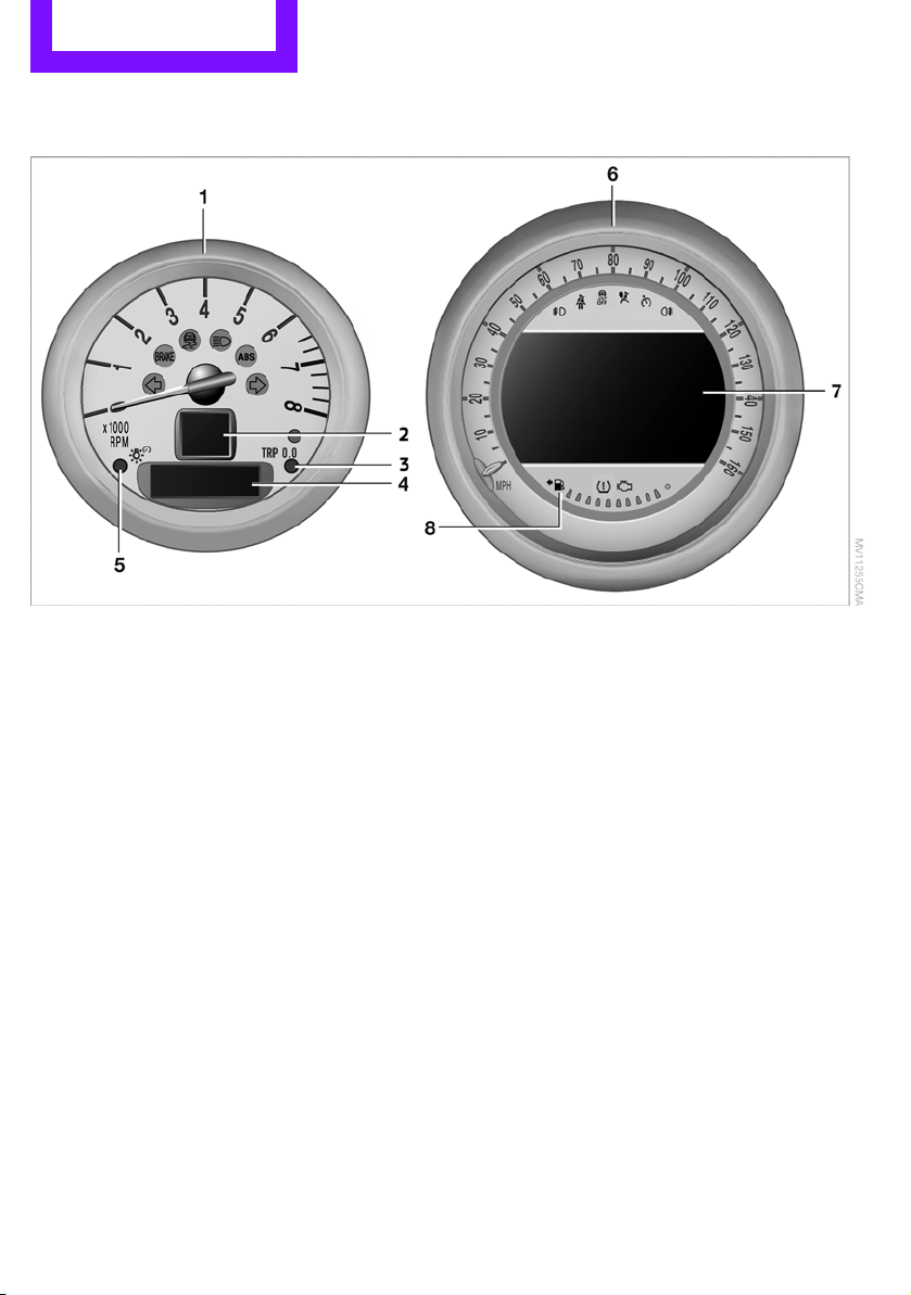
Displays
1 Tachometer 70
with indicator and warning lamps 13
2 Display for
> Current vehicle speed 71
> Indicator and warning lamps 13
3 Resetting the trip odometer 71
4 Display for
> Position of automatic transmission 62
> Computer 71
> Date of next scheduled service, and
remaining distance to be driven 75
> Odometer and trip odometer 71
> Initializing the Flat Tire Monitor 87
> Resetting the Tire Pressure Monitor 90
> Settings and information 73
> Personal Profile settings 28
5 Instrument lighting 99
6 Speedometer
with indicator and warning lamps 13
7 Control Display 18
8 Fuel gauge 70
12
Page 14
Indicator and warning
Online Edition for Part no. 01 40 2 904 077 - © 03/12 BMW AG
lamps
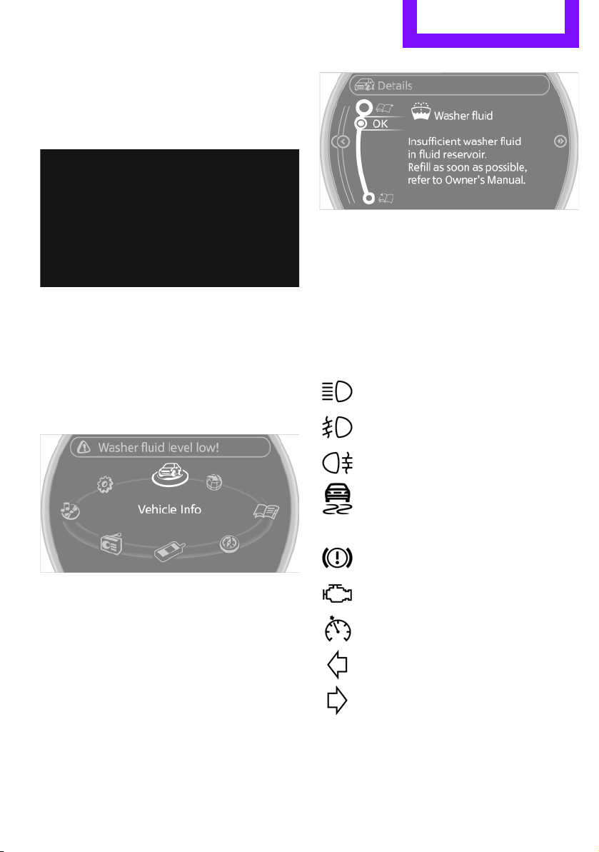
The concept
Indicator and warning lamps can light up in
various combinations and colors in indicator
area 1 or 2.
Some lamps will be tested for proper functioning
when the engine is started or the ignition is
switched on and will therefore light up briefly.
Cockpit AT A GLANCE
You can call up more information, e.g. on the
cause of a malfunction and on how to respond,
via Check Control, page 77.
In urgent cases, this information will be shown
as soon as the corresponding lamp lights up.
Indicator lamps without text messages
The following indicator lamps in display area 1
indicate certain functions:
High beams/headlamp flasher 98
Explanatory text messages
Text messages at the upper edge of the Control
Display explain the meaning of the displayed
indicator and warning lamps.
Front fog lamps 99
Rear fog lamp 99
Lamp flashes:
DSC or DTC is regulating the drive
forces in order to maintain driving
stability 83
Parking brake applied 62
Engine malfunction with adverse effect
on exhaust emissions 226
Cruise control 68
Turn signals 65
13
Page 15
AT A GLANCE Cockpit
Online Edition for Part no. 01 40 2 904 077 - © 03/12 BMW AG
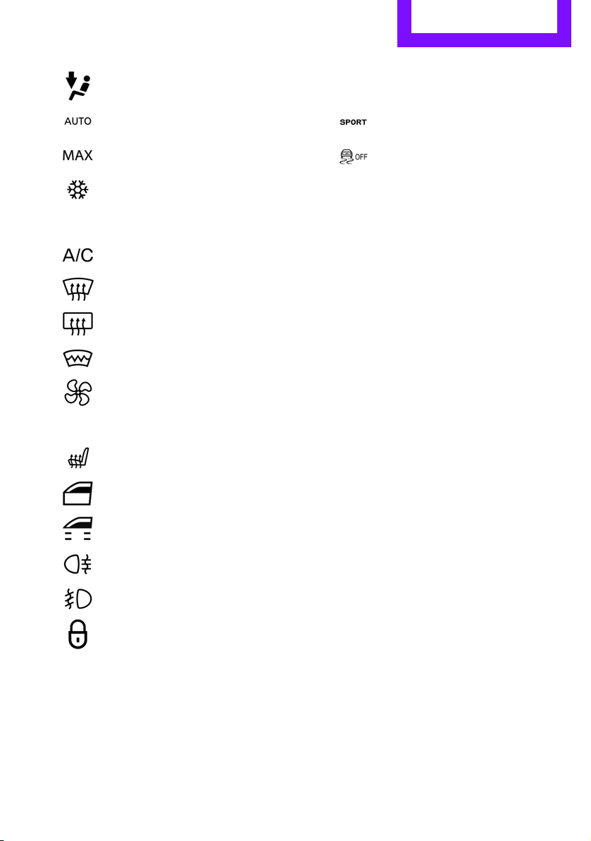
Around the center console
1 Hazard warning flashers
2 Speedometer with Control Display 12
3 Radio/CD
Selecting waveband
Changing the audio source
Changing the radio station or track
Ejecting CD
4 Air conditioner or automatic climate
14
control 101
Temperature
Recirculated-air mode
Air distribution for air conditioner
Air distribution to the windshield
Air distribution to the upper body
area
Page 16
Cockpit AT A GLANCE
Online Edition for Part no. 01 40 2 904 077 - © 03/12 BMW AG
Air distribution to the footwell
Automatic air distribution and flow
rate
Maximum cooling
or
Cooling function
Defrosting windows
Rear window defroster
Windshield heating
Air flow rate
5 Switches in the center console
Seat heating 53
6 USB audio interface 160
7 Buttons on the center console
Sport button 85
Driving stability control systems
Dynamic Stability Control DSC 83
Dynamic Traction Control DTC 84
8 Changing to a different menu on the Control
Display
9 MINI joystick 17
Move in four directions, turn or press
10 Accessing the main menu on the Control
Display 18
Power windows 38
MINI Convertible: central power
window unit 39
Rear fog lamp 98
Front fog lamps 98
Central locking system, inside 32
15
Page 17
AT A GLANCE Cockpit
Online Edition for Part no. 01 40 2 904 077 - © 03/12 BMW AG
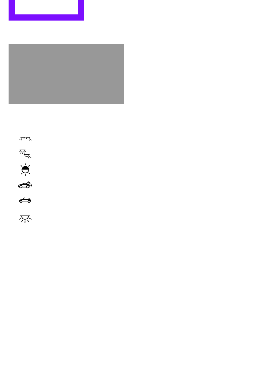
Around the headliner
1 Indicator/warning lamp for front passenger
airbags 94
2 Switch panel
Reading lamps 99
MINI Roadster: interior lamps/
reading lamps 99
Color of ambient lighting 100
MINI Coupe, MINI Roadster: extending and retracting spoiler manually
MINI Convertible, MINI Roadster:
Opening and closing the sunroof or
convertible top 39
Interior lamps 99
16
Page 18
Onboard computer AT A GLANCE
Online Edition for Part no. 01 40 2 904 077 - © 03/12 BMW AG
Onboard computer
Vehicle equipment
In this chapter, all production, country, and
optional equipment that is offered in the model
range is described. Equipment is also described
that is not available because of, for example,
selected options or country version. This also
applies to safety related functions and systems.
The concept
The onboard computer integrates the functions
of a large number of switches. This allows these
functions to be operated from a single central
position. The following section provides an
introduction to basic menu navigation. The control of the individual functions is described in
connection with the relevant equipment.
Make entries only when traffic and road
conditions permit; otherwise, you may
endanger vehicle occupants and other road
users by being distracted.<
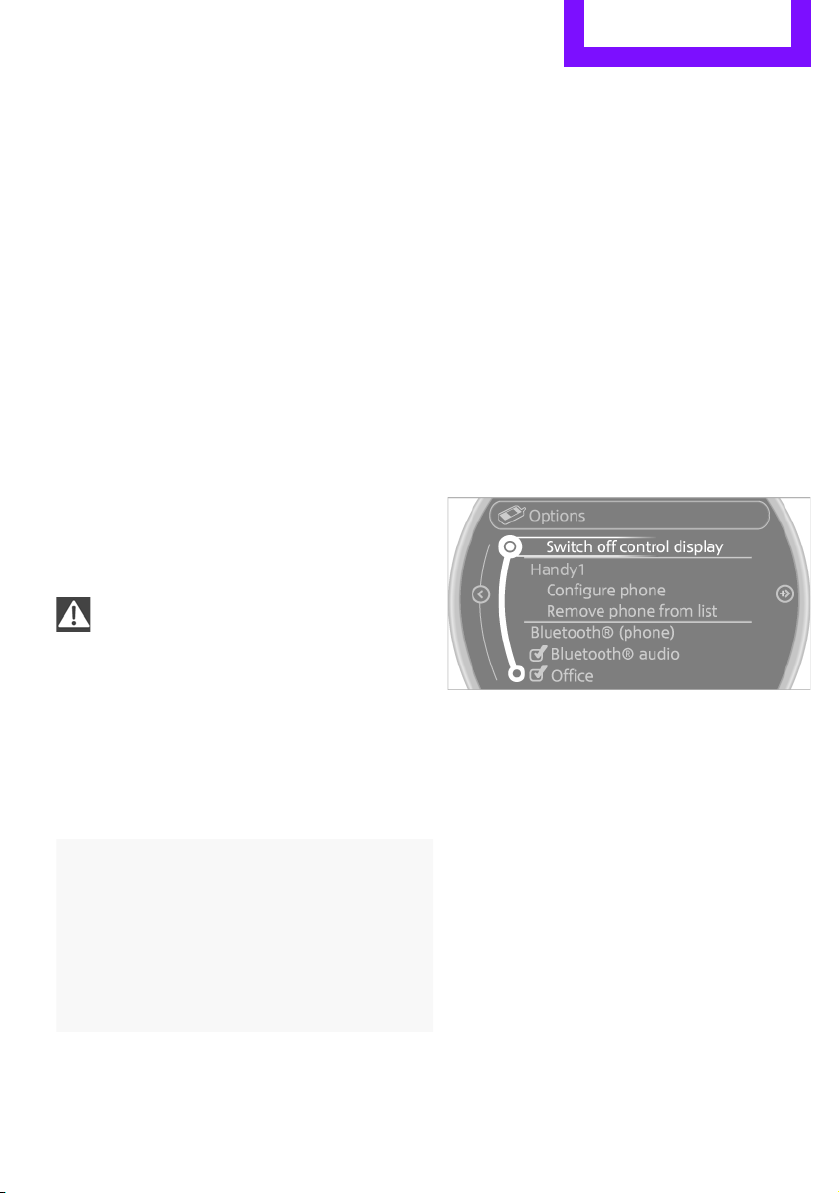
Overview of operating elements
Control Display
Notes
> When cleaning the Control Display, follow
the care instructions.
> Do not place any objects in the area of the
Control Display; otherwise, the Control
Display can be damaged.
Switching Control Display off/on
1. Move the MINI joystick to the right repeat-
edly until the "Options" menu is displayed.
2. "Switch off control display"
To switch on, press the MINI joystick.
Controls
1 Control Display
2 MINI joystick with buttons
17
Page 19
AT A GLANCE Onboard computer
Online Edition for Part no. 01 40 2 904 077 - © 03/12 BMW AG
MINI joystick with buttons
Selecting menu items and carrying out settings.
1. Turning 1 and pressing 2.
2. Tilting in four directions.
Buttons on MINI joystick
Operating principle
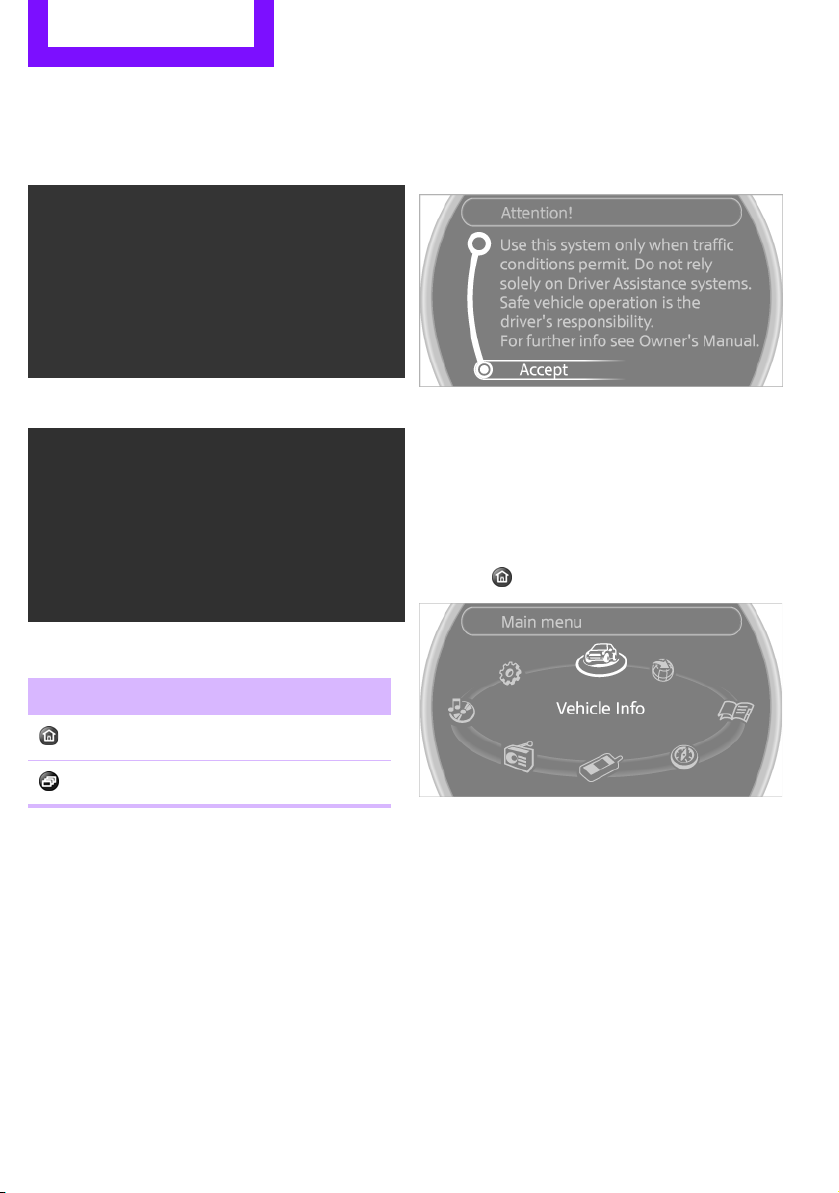
As of radio readiness, the following message
appears on the Control Display:
To hide the message:
Press the MINI joystick.
The main menu is displayed.
The message is automatically hidden after
approx. 10 seconds.
Opening the main menu
Press the button.
Button Function
Accessing the main menu
Changing to another menu
All functions of the onboard computer can be
accessed via the main menu.
18
Page 20
Onboard computer AT A GLANCE
Online Edition for Part no. 01 40 2 904 077 - © 03/12 BMW AG
Selecting a menu item
Menu items displayed in white can be selected.
1. Turn the MINI joystick until the desired
menu item is highlighted.
2. Press the MINI joystick.
A new menu is displayed or the function is
executed.
Using the button on the MINI joystick:
Press the button.
Each time that the button is pressed, the menu
items "Navigation", "Radio", "CD/Multimedia"
and "Telephone" are called up, one after
another.
Arrows pointing left or right indicate that
additional panels can be accessed.
View of a menu that has been called up
In general, when a menu is called up, the panel
that was last selected in the menu is displayed.
To display the first panel of the menu:
Move the MINI joystick as often to the left as
necessary until the first panel is displayed.
Opening the Options menu
Move the MINI joystick to the right repeatedly
until the "Options" menu is displayed.
Menu items in the Owner's Manual
In the Owner's Manual, the menu items that
should be selected are depicted in quotation
marks, e.g. "Settings".
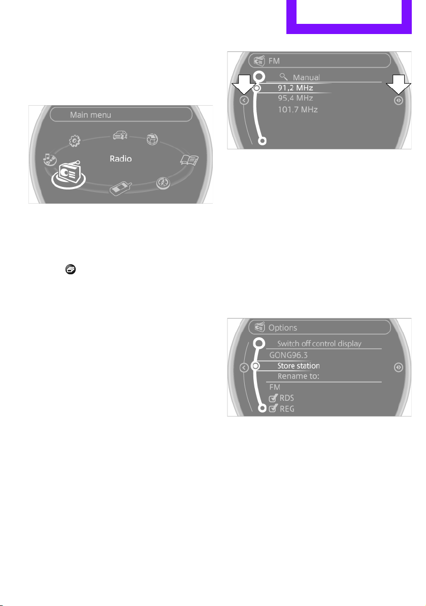
Changing between panels
After selecting a menu item, e.g. "Radio", a new
menu is displayed on a panel. The panels can
overlap.
> Move the MINI joystick to the left.
Current panel is closed and the previous
panel is displayed.
> Move the MINI joystick to the right.
The new panel is opened and placed on top.
The following is displayed in the "Options"
menu:
> Screen settings.
> Control options for the selected menu.
19
Page 21
AT A GLANCE Onboard computer
Online Edition for Part no. 01 40 2 904 077 - © 03/12 BMW AG
Adjusting settings
1. Select a field.
2. Turn the MINI joystick until the desired
setting is displayed.
3. Press the MINI joystick to confirm the
setting.
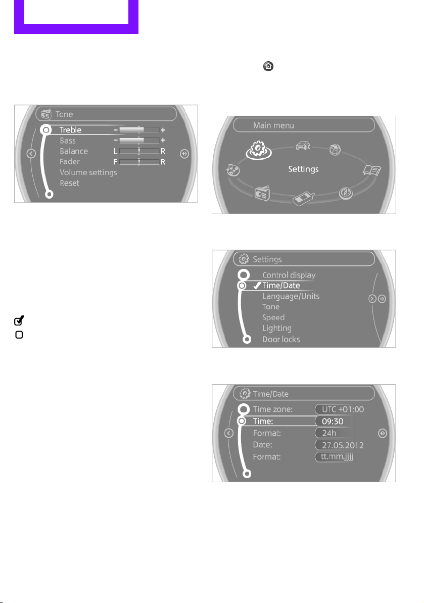
Activating/deactivating functions
Some menu items are preceded by a check box.
It indicates whether the function is activated or
deactivated.
Selecting the menu item activates or deactivates
the function.
Function is activated.
Function is deactivated.
Example: setting the clock
1. Press the button.
The main menu is displayed.
2. Turn the MINI joystick until "Settings" is
selected, and press the MINI joystick.
3. Turn the MINI joystick until "Time/Date" is
selected, and press the MINI joystick.
4. Turn the MINI joystick until "Time:" is
5. Turn the MINI joystick to set the hours and
6. Turn the MINI joystick to set the minutes and
20
selected, and press the MINI joystick.
press the MINI joystick.
press the MINI joystick.
Page 22
Onboard computer AT A GLANCE
Online Edition for Part no. 01 40 2 904 077 - © 03/12 BMW AG
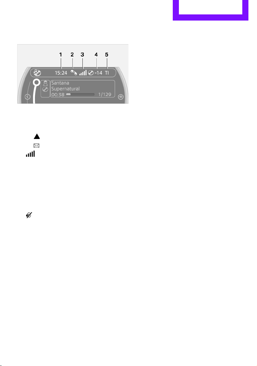
Status information
1 Time
2 Telephone status
> Incoming, outgoing or missed call
> Roaming active
> Text message received
3 Reception strength of the wireless
network, depends on the mobile phone
4 Display for:
> Entertainment:
Radio, CD, external devices
> Telephone:
Name of the mobile phone paired with
the vehicle
5 Sound output is switched off or
display for traffic bulletins:
> "TI":
Traffic bulletins are switched on.
> No display:
Traffic bulletins are switched off.
Other displays:
Status information is temporarily hidden during
Check Control message displays or entries via
the voice activation system.
21
Page 23

AT A GLANCE Letters and numbers
Online Edition for Part no. 01 40 2 904 077 - © 03/12 BMW AG
Letters and numbers
Vehicle equipment
In this chapter, all production, country, and
optional equipment that is offered in the model
range is described. Equipment is also described
that is not available because of, for example,
selected options or country version. This also
applies to safety related functions and systems.
Entering letters and numbers
1. Turn the MINI joystick: select the letters or
numbers.
2. Select additional letters or numbers if
needed.
3. "OK": confirm entry.
Switching between letters and numbers
Depending on the menu, you can switch
between entering letters and numbers:
Symbol Function
Entering letters
Entering numbers
Switching between uppercase and
lowercase letters
Depending on the menu, you can switch
between entering uppercase letters and
lowercase letters:
Symbol Function
Move the MINI joystick
forward: to switch from
uppercase letters to lowercase letters
Move the MINI joystick
forward: to switch from
lowercase letters to uppercase letters
Symbol Function
Press the MINI joystick:
delete one letter or
number
Press and hold the
MINI joystick: delete all
letters or numbers
Enter a blank space
Wordmatch concept
Entry of names and addresses: the selection is
narrowed down every time a letter is entered
and letters may be added automatically.
The entries are continuously compared to the
data stored in the vehicle.
> The only letters offered for entry are those
> Destination search: town/city names can be
22
for which data are available.
entered with the spelling used in any of the
languages available on the Control Display.
Page 24
Voice activation system AT A GLANCE
Online Edition for Part no. 01 40 2 904 077 - © 03/12 BMW AG
Voice activation system
Vehicle equipment
In this chapter, all production, country, and
optional equipment that is offered in the model
range is described. Equipment is also described
that is not available because of, for example,
selected options or country version. This also
applies to safety related functions and systems.
The concept
> By using the voice activation system, individ-
ual functions that are displayed on the
Control Display can be operated via voice
commands. The system supports the entry
process by means of announcements.
> Functions that can only be used while the
vehicle is not moving cannot be operated via
the voice activation system.
> The system includes a special microphone in
the vicinity of the rearview mirror.
Prerequisite
So that voice commands can be identified, set a
language on the Control Display that is supported by the voice activation system.
To set the language, see page 80.
Symbols in the Owner's Manual
{...} Say the specified commands word for
word.
{{...}} Indicates responses of the voice
activation system.
Saying commands
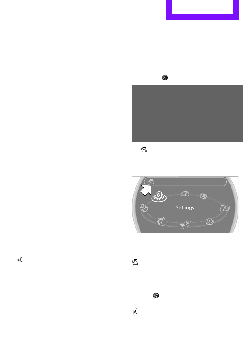
Activating voice activation system
1. Press the button on the steering wheel.
This symbol on the Control Display and
an acoustic signal indicate that the voice
activation system is ready to receive spoken
commands.
2. Say the command.
The command appears on the Control
Display.
This symbol is displayed on the Control Dis-
play when you can enter additional commands.
Terminating or canceling voice
activation system
Press the button on the steering wheel
or
{Cancel}
23
Page 25
AT A GLANCE Voice activation system
Online Edition for Part no. 01 40 2 904 077 - © 03/12 BMW AG
Commands
Individual menu items on the Control Display
can be voiced as commands.
The commands that are possible depend upon
which menu is currently shown on the Control
Display.
There are short commands for functions in the
main menu.
Some list items, for example telephone book
listings, can also be selected using the voice activation system. In particular, say the list items
exactly as they are displayed in the respective
list.
Having the possible commands
read aloud
Having the possible commands read aloud:
{Voice commands}
For example if you have selected "CD" the system will read aloud the possible commands for
operating the CD player.
Help for the voice activation system
Calling up Help:
{Help}
Additional commands for Help:
> {Help with examples}: information about
the current operating options and the most
important commands for them are
announced.
> {Help with voice activation}: information
regarding the principles behind the voice
activation system is announced.
Carrying out functions through short
commands
Main menu functions can be executed immediately by short commands, almost regardless
of which menu item is selected, e.g., {Vehicle
status}.
List of voice activation system short commands,
see page 260.
Opening the main menu
{Main menu}
Example: selecting the track of a CD
1. Switch on Entertainment sound output if
necessary.
2. Press the button on the steering wheel.
3. Select the music track, e.g.:
{C D track …}
The system replies:
{{Track …}}
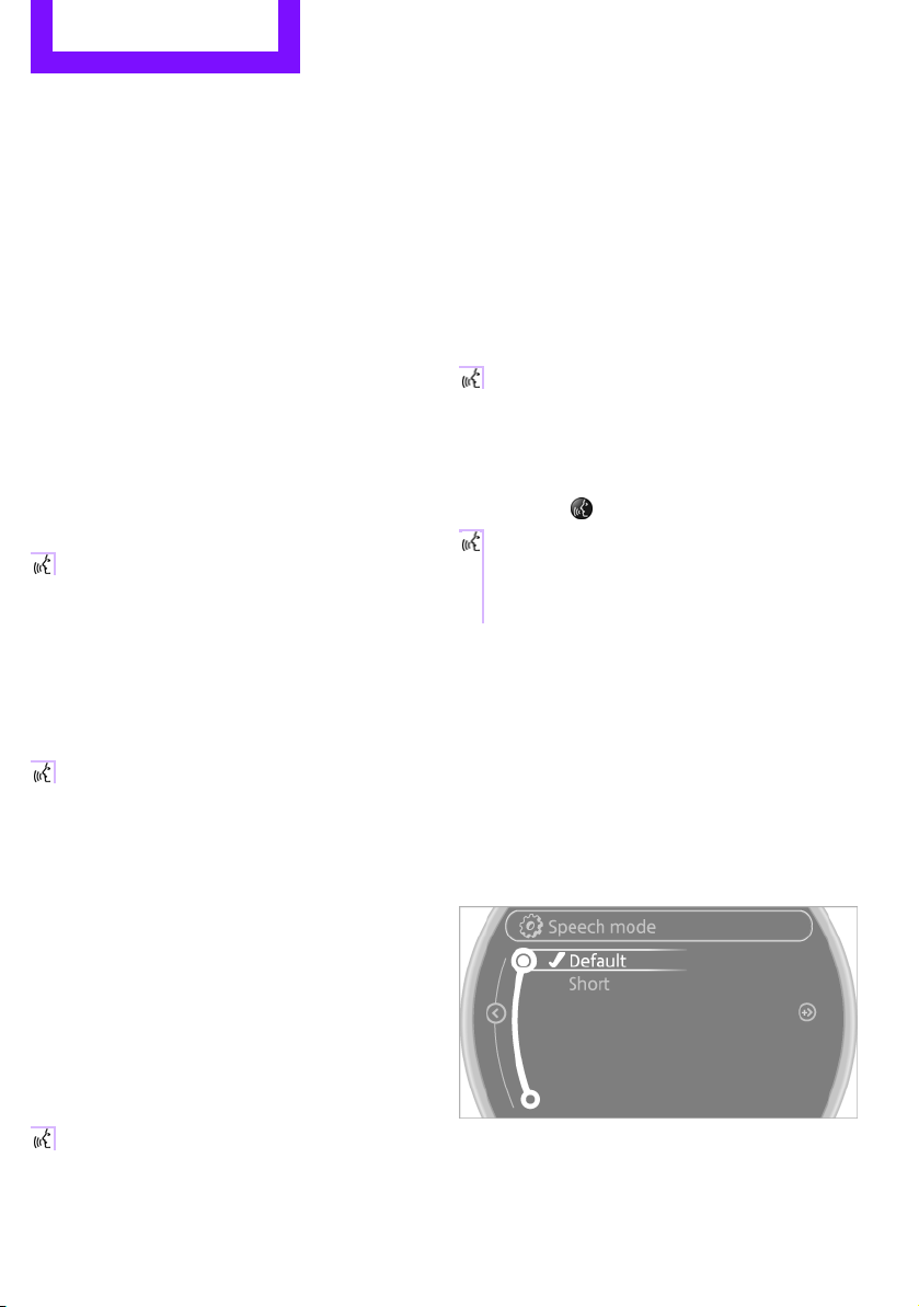
Setting the voice dialog
You can set whether the voice activation system
uses the standard dialog or the short version.
With the short version of the spoken dialog, the
requests and responses of the voice activation
system are shortened.
1. "Settings"
2. "Language/Units"
3. "Speech mode:"
Using alternative commands
There are often a number of commands to run a
function, e.g.:
{Radio} or {Radio on}
4. Select a setting:
24
> "Default"
> "Short"
Page 26

Voice activation system AT A GLANCE
Online Edition for Part no. 01 40 2 904 077 - © 03/12 BMW AG
Notes
For voice commands, bear in mind the
following:
> Do not use the voice activation system to
initiate an emergency call. In stressful
situations, the voice and vocal pitch can
change. This can unnecessarily delay the
establishment of a telephone connection.
> Pronounce the commands and digits
smoothly and at normal volume, avoiding
excessive emphases and pauses. The same
applies to spelling when entering a destination for navigation.
> Always speak the commands in the
language of the voice activation system.
> When selecting a radio station, use the
standard pronunciation of the station name.
{Select station} e.g. WPLJ
> Keep the doors and windows closed to
prevent interference from outside noise.
> Avoid ambient noise in the vehicle while
speaking.
25
Page 27
Handle Me.
Online Edition for Part no. 01 40 2 904 077 - © 03/12 BMW AG
Page 28

AT A GLANCE
Online Edition for Part no. 01 40 2 904 077 - © 03/12 BMW AG
CONTROLS
DRIVING TIPS
NAVIGATION
ENTERTAINMENT
COMMUNICATIONS
MOBILITY
REFERENCE
Page 29

CONTROLS Opening and closing
Online Edition for Part no. 01 40 2 904 077 - © 03/12 BMW AG
Opening and closing
Vehicle equipment
In this chapter, all production, country, and
optional equipment that is offered in the model
range is described. Equipment is also described
that is not available because of, for example,
selected options or country version. This also
applies to safety related functions and systems.
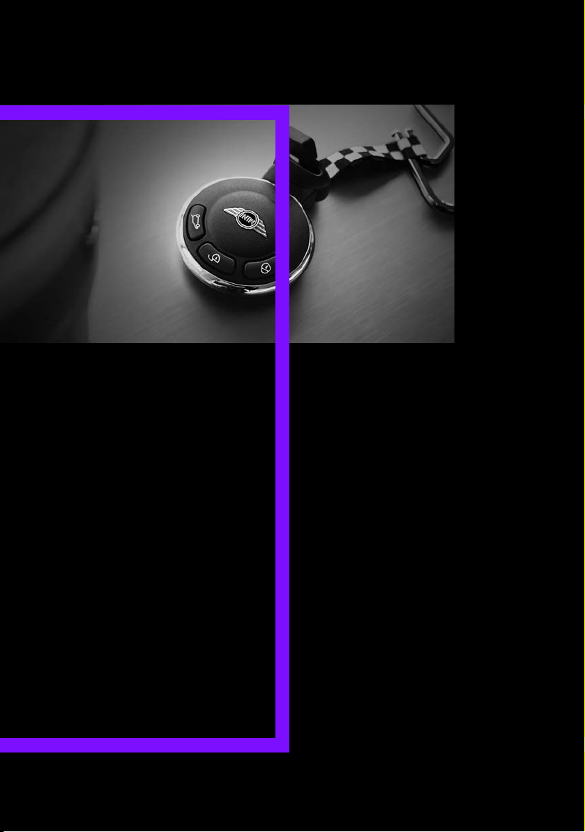
Keys/remote controls
Buttons on the remote control
1 Opening the tailgate
2 Unlocking
3 Locking
General information
Each remote control contains a rechargeable
battery that is recharged when it is in the
ignition lock while the car is being driven. You
should therefore use each remote control at
least twice a year to maintain the charge status.
In vehicles equipped with Comfort Access, the
remote control contains a replaceable battery,
page 38.
If more than one remote control unit is used, the
settings called up and implemented depend on
which remote control is recognized when the
car is unlocked, refer to Personal Profile,
page 28.
In addition, information about service requirements is stored in the remote control, refer to
Service data in the remote control, page 225.
New remote controls
Your MINI dealer can supply new remote controls as additional units or as replacements in the
event of loss.
Integrated key
Press button 1 to release the key.
The integrated key fits the following locks:
> Driver's door, page 31
> MINI Convertible, MINI Roadster: glove
compartment, page 107
> MINI Convertible: locking the rear seat
backrest, page 118
> MINI Coupe, MINI Roadster: opening for
loading, page 117
Personal Profile
The concept
The functions of your MINI can be set individually. By means of Personal Profiles, most of these
settings are stored for the remote control
currently in use. When you unlock the car, the
remote control is recognized and the settings
stored for it are called up and implemented.
28
Page 30

Opening and closing CONTROLS
Online Edition for Part no. 01 40 2 904 077 - © 03/12 BMW AG
This means that your settings will be activated
for you, even if in the meantime your car was
used by someone else with another remote
control and the corresponding settings.
At most three remote controls can be set for
three different people. A prerequisite is that
each person uses a separate remote control.
Personal Profile settings
For more information on specific settings, refer
to the specified pages.
> Response of the central locking system
when the car is being unlocked 30
> Automatic locking of the vehicle 33
> Triple turn signal activation 65
> Settings for the displays on the onboard
computer, in the speedometer and in the
tachometer:
> 12 h/24 h mode of the clock 76
> Date format 77
> Brightness of the Control Display 80
> Language on the Control Display 80
> Units of measure for fuel consumption,
distance covered/remaining distances
and temperature 74
> Light settings:
> Pathway lighting 97
> Daytime running lights 97
> Automatic climate control: activating/
deactivating the AUTO program, setting the
temperature, air volume and air
distribution 103
> Entertainment:
> Tone control 147
> Adjusting volume levels 147
Central locking system
The concept
The central locking system is ready for operation
whenever the driver's door is closed.
The system simultaneously engages and
releases the locks on the following:
> Doors
> Tailgate
> Fuel filler flap
Operating from outside
> Via the remote control
> Using the door lock
> In cars with Comfort Access, via the door
handles on the driver's and passenger's
sides
The anti-theft system is also operated at the
same time. It prevents the doors from being
unlocked using the lock buttons or door handles. The remote control can also be used to
switch on/off the welcome lamps and interior
lamps. The alarm system is also activated or
deactivated, page 34.
Operating from inside
Button for central locking system, page 32.
In the event of a sufficiently severe accident,
the central locking system unlocks automatically. In addition, the hazard warning flashers
and interior lamps come on.
Opening and closing: from outside
Persons or animals in a parked vehicle
could lock the doors from the inside. Take
the key with you when you leave the vehicle
so that the vehicle can be opened from the
outside.<
29
Page 31

CONTROLS Opening and closing
Online Edition for Part no. 01 40 2 904 077 - © 03/12 BMW AG
Using the remote control
Unlocking
Press the button.
The welcome lamps and interior lamps come on.
Unlocking mode
You can also set which parts of the car are
unlocked. The setting is stored for the remote
control in use.
1. "Settings"
2. "Door locks"
3. "Unlock button"
4. Select a menu item:
> "All doors"
Press the button once to unlock
the entire vehicle.
> "Driver's door only"
Press the button once to unlock
only the driver's door and the fuel filler
flap.
Press the button twice to unlock the
entire vehicle.
Convenient opening
Press and hold the button.
The power windows open. In the MINI Convertible, the windows and the sliding sunroof are
opened.
In order to open the convertible top of your MINI
Convertible: release button and push again until
the convertible top is completely open. The side
window remains open.
With Comfort Access: when you are close to the
vehicle, the windows are raised after the convertible top opens if you continue pressing the
button.
Convenient closing is not possible by
means of the remote control.<
Locking
Press the button.
Do not lock the vehicle from the outside if
there is any person inside, because the
vehicle cannot be unlocked from inside without
special knowledge.<
MINI Convertible: convenient closing
When you are close to the vehicle, the remote
control for Comfort Access can be used to close
the convertible top and the windows.
Press and hold the button.
The convertible top and the windows are closed.
Watch during the closing process to be
sure that no one is injured. Releasing the
button interrupts the closing process.<
Setting confirmation signals
To have the vehicle confirm when it has been
locked or unlocked.
1. "Settings"
2. "Door locks"
30
Page 32

Opening and closing CONTROLS
Online Edition for Part no. 01 40 2 904 077 - © 03/12 BMW AG
3. "Flash when lock/unlock"
4. Press the MINI joystick.
Switching on interior lamps
While the car is locked:
Press the button.
You can also use this function to locate your
vehicle in parking garages, etc.
Unlocking the tailgate
Press the button for approx. 1 second
and then release it.
When it is opened, the tailgate swings out
and up toward the rear. Make sure that
adequate clearance is available before opening.
To prevent accidentally locking yourself out, do
not place the key down in the cargo area. If the
tailgate was locked before opening, it will be
locked again after it is closed.
Before and after each trip, check that the tailgate has not been inadvertently unlocked.<
For US owners only
The transmitter and receiver units comply with
part 15 of the FCC/Federal Communications
Commission regulations. Operation is governed
by the following:
FCC ID:
LX8766S
LX8766E
LX8CAS
Compliance statement:
This device complies with part 15 of the FCC
Rules. Operation is subject to the following two
conditions:
> This device must not cause harmful
interference, and
> This device must accept any interference
received, including interference that may
cause undesired operation.
Any unauthorized modifications or
changes to these devices could void the
user's authority to operate this equipment.<
Using the door lock
Malfunctions
The remote control may malfunction due to
local radio waves. If this occurs, unlock and lock
the car at the door lock with the integrated key.
If the car can no longer be locked with a remote
control, the battery in the remote control is
discharged. Use this remote control during an
extended drive; this will recharge the battery,
page 28.
You can set which parts of the car are unlocked,
page 29.
Do not lock the vehicle from the outside if
there is any person inside, because the
vehicle cannot be unlocked from inside without
special knowledge.<
31
Page 33

CONTROLS Opening and closing
Online Edition for Part no. 01 40 2 904 077 - © 03/12 BMW AG
When there is no alarm system or Comfort
Access, only the driver's door is locked
with the door lock.<
To lock all doors, the fuel filler flap, and the
tailgate together:
With the doors closed, press the interior central
locking button, page 32, to lock the vehicle.
Unlocking and opening the driver or passenger
door, page 32.
Lock the vehicle.
> Lock the driver's door with the integrated
key via the door lock, or
> Press the safety lock button on the
passenger's door and close the door
from the outside.
Convenience operation
With an alarm system or Comfort Access, the
windows can be operated via the door lock.
Opening/closing
Hold the key in the position for unlocking or
locking.
In the MINI Convertible, the convertible top
closes first, followed by the folding sunroof, and
finally the side windows close.
During the roof closing process (in case of
the convertible top also during the open-
ing process) ensure no one gets pinched.
Releasing the key stops the operation.<
Manual operation
In the event of an electrical malfunction, the
driver's door can be unlocked or locked by turning the integrated key in the door lock to the end
positions.
Opening and closing: from inside
The switch locks or unlocks the doors and
tailgate when the doors are closed, but the antitheft system is not activated. The fuel filler flap
remains unlocked.
Unlocking and opening
> Either unlock the doors together using the
switch for the central locking system and
then pull the door handle above the armrest
or
> Pull on the door handle of either door twice:
the first time unlocks the door, the second
time opens it.
Locking
> Press the switch or
> Press down the safety lock button of a door.
To prevent you from being locked out, the
open driver's door cannot be locked using
the lock button.
Persons or animals in a parked vehicle
could lock the doors from the inside. Take
the key with you when you leave the vehicle
so that the vehicle can be opened from the
outside.<
32
Page 34

Opening and closing CONTROLS
Online Edition for Part no. 01 40 2 904 077 - © 03/12 BMW AG
Automatic locking
You can also set the situations in which the car
locks. The setting is stored for the remote
control in use.
1. "Settings"
2. "Door locks"
3. Select a menu item:
> "Lock if no door is opened"
The central locking system automatically
locks the vehicle after a short time if no
door has been opened.
> "Lock after start. to drive"
The central locking system locks the
vehicle as soon as you begin to drive.
Press the button in the handle, arrow, or the
button of the remote control, for an
extended period. The tailgate is unlocked and
can be opened.
MINI Convertible
Tailgate
To avoid damage, make sure there is
sufficient clearance before opening the
tailgate.<
While driving, sharp objects or objects
with edges may strike against the rear
window and damage the heating element for
the rear window. Assure that there are no
objects with sharp edges near the rear
window.<
Opening
In some market-specific versions, the tail-
gate cannot be unlocked using the remote
control unless the vehicle is unlocked first.<
The maximum load that may be placed on
the open tailgate is 175 lbs/80 kg.<
Manual unlocking
In the event of an electrical malfunction, you can
also manually release the tailgate.
MINI Coupe, MINI Roadster:
Pull on the handle. The tailgate is released.
33
Page 35

CONTROLS Opening and closing
Online Edition for Part no. 01 40 2 904 077 - © 03/12 BMW AG
MINI Convertible:
1. Use the integrated key and open the back-
rest lock 1.
2. Press button 2 and fold down backrest
together with the belt strap.
3. Pull the handle, refer to arrow. The tailgate is
released.
Closing
Make sure that the closing path of the tailgate is clear; otherwise, injuries may
occur.<
Take the remote control with you and do
not put it into the luggage compartment:
otherwise, the remote control can be locked in
the vehicle when the tailgate is closed.<
MINI Coupe
The handle recesses on the interior trim panel of
the tailgate make it easier to pull it down.
MINI Roadster
MINI Convertible, MINI Roadster:
Emergency unlocking
A handle recess on the interior trim panel of the
tailgate make it easier to pull it down.
Alarm system
Pull on the handle in the luggage compartment.
The tailgate is unlocked.
34
The concept
The alarm system, when activated, reacts if:
> A door, the engine compartment lid or the
> There is movement inside the car
tailgate is opened
Page 36

Opening and closing CONTROLS
Online Edition for Part no. 01 40 2 904 077 - © 03/12 BMW AG
> The car’s inclination changes, for example if
an attempt is made to jack it up and steal the
wheels or to raise it prior to towing it away
> There is an interruption in the power supply
from the battery
The alarm system briefly indicates unauthorized
entry or tampering by means of:
> An acoustic alarm
> Switching on the hazard warning flashers
Arming and disarming
General information
Whenever the car is locked or unlocked, the
alarm system is armed or disarmed.
Door lock with armed alarm system
Because of the design, unlocking the door lock
may trigger the alarm in some countries.
To turn off the alarm, unlock the vehicle using
the remote control or switch on the ignition.
Tailgate with armed alarm system
Even when the alarm system is armed, you can
open the tailgate by means of the button
on the remote control.
When you subsequently close the tailgate it is
again locked and monitored.
Panic mode
You can activate the alarm system if you find
yourself in a dangerous situation.
Press the button for at least two seconds.
Switching off the alarm:
Press any button.
Switching off an alarm
> Unlock the car with the remote control.
> Insert the key fully into the ignition lock.
> In cars with Comfort Access, press the button
on the door lock.
Display on the revolution counter
When the system is armed, all LEDs pulse. After
approx. 16 minutes one LED flashes.
> LEDs pulse or LED flashes: system is armed.
> One LED flashes at short intervals:
Doors, the hood or the tailgate are not properly closed. Even if these are not closed fully,
the remaining items are deadlocked and the
LEDs pulse after approx. 10 seconds for
approx. 16 minutes. Afterwards, one LED
flashes.
The interior movement detector is not
activated.
> LEDs go out after the vehicle is unlocked:
No attempt was made to tamper with the
car.
> LEDs flash after unlocking until the key is
inserted in the ignition, but for no longer
than approx. 5 minutes: an attempt was
made to tamper with the vehicle.
Tilt alarm sensor
The vehicle's inclination is monitored. The alarm
is triggered, for instance, if an attempt is made
to steal the vehicle's wheels or tow it away.
Interior movement detector
Before the interior movement detector can
operate correctly, the windows and glass roof
must be closed.
35
Page 37

CONTROLS Opening and closing
Online Edition for Part no. 01 40 2 904 077 - © 03/12 BMW AG
MINI Convertible, MINI Roadster
The passenger compartment is monitored up to
the height of the seat's surface. This way, the
anti-theft alarm system including the interior
motion sensor are armed, even if the convertible
top is open. Falling objects, e.g. tree leaves, may
trigger a false alarm, refer to Avoiding false
alarms.
Avoiding false alarms
The tilt alarm sensor and the interior movement
detector can be switched off together.
This prevents false alarms, e.g. in the following
situations:
> In duplex garages
> When being transported on car-carrying
trains, ferries or trailers
> If pets are to remain inside the car
Switching off the tilt alarm sensor and
interior movement detector
> Press the button on the remote
control twice in succession.
> Lock the vehicle twice with the integrated
key.
LEDs flash in short succession for approx.
2seconds.
The tilt alarm sensor and the interior movement
detector are switched off until the car is next
unlocked and locked.
Comfort Access
The concept
Access to the vehicle is possible without the use
of the remote control. All you need to do is wear
the remote control close to your body, e.g. in
your jacket pocket. The vehicle automatically
detects the remote control within the immediate vicinity or in the passenger compartment.
Comfort Access supports the following
functions:
> Unlocking/locking the vehicle
> Unlocking the tailgate separately
> Starting the engine
> MINI Convertible: convenient closing and
soft-top control with the remote control for
Comfort Access
> MINI Coupe, MINI Roadster: closing the side
windows
Functional requirements
> There are no external malfunction sources in
the vicinity.
> For locking, the remote control must be
outside of the vehicle.
> The vehicle cannot be locked or unlocked
again until after approx. 2 seconds.
> The engine can only be started if the remote
control is in the vehicle.
> The doors and tailgate must be closed to
operate the windows.
Comparison to standard remote controls
The indicated function can be operated by
pressing the buttons or via Comfort Access.
Instructions on opening and closing are found
starting on page 28.
is checking whether a remote control is inside
the vehicle. Repeat the opening or closing
procedure, if necessary.<
36
If you notice a brief delay while opening or
closing the windows or cover, the system
Page 38

Opening and closing CONTROLS
Online Edition for Part no. 01 40 2 904 077 - © 03/12 BMW AG
Unlocking
Press button 1.
Depending on the setting, refer to Unlocking
mode on page 30, only the driver's door or the
entire vehicle is unlocked.
Press the button again to lock the vehicle
again.<
Convenient opening with the remote control,
refer to page 30.
Locking
Press button 1.
If there is a remote control inside the vehicle,
then windows can be opened and closed after
radio readiness is achieved. In addition, the
convertible top on the MINI Cabrio and MINI
Roadster can be closed.
Unlocking the tailgate separately
Press the button on the outside of the tailgate.
Corresponds to pressing the button.
If the vehicle detects that a remote control
has been accidentally left inside the
locked vehicle's cargo area after the tailgate is
closed, the tailgate will reopen slightly. The hazard warning flashers flash and an acoustic signal
sounds.<
Windows, electric
If the engine is switched off, you can still operate
the windows so long as a door or the tailgate has
not been opened.
If the doors and tailgate are closed again and the
remote control is located inside the vehicle, the
windows can be operated again.
Insert the remote control into the ignition lock to
be able to operate the windows when the
engine is switched off and the doors are open.
Switching on radio readiness
Switch on radio readiness by pressing the
Start/Stop button, page 60.
Do not depress the brake or the clutch;
otherwise, the engine will start.<
Starting the engine
The engine can be started or the ignition can be
switched on when a remote control is inside the
vehicle. It is not necessary to insert a remote
control into the ignition lock, page 60.
Switching off the engine in cars with
automatic transmission
The engine can only be switched off when the
selector lever is in position P, page 62.
To switch the engine off when the selector lever
is in position N, the remote control must be in
the ignition lock.
Before driving a vehicle with automatic
transmission into a car wash
1. Insert remote control into ignition lock.
2. Depress the brake.
3. Move the selector lever to position N.
4. Switch off the engine.
The vehicle can roll.
Malfunction
Comfort Access may malfunction due to local
radio waves, e.g. due to the presence of a
mobile phone in the immediate vicinity of the
remote control or the charging of a mobile
phone in the vehicle.
If this happens, open or close the vehicle via the
buttons on the remote control or using the integrated key.
Insert the remote control into the ignition lock
and start the engine.
37
Page 39

CONTROLS Opening and closing
Online Edition for Part no. 01 40 2 904 077 - © 03/12 BMW AG
Warning lamps
The warning lamp lights up when an
attempt is made to start the engine: the
engine cannot be started. The remote
control is not inside the vehicle or is malfunctioning. Take the remote control with you inside
the vehicle or have it checked. If necessary,
insert another remote control into the ignition
lock.
The warning lamp lights up when the
engine is running: the remote control is
no longer inside the vehicle. After the
engine is switched off, the engine can only be
restarted within approx. 10 seconds.
The indicator lamp comes on and a
message appears on the Control
Display: replace the battery in the
remote control.
Replacing the battery
The remote control for Comfort Access contains
a b atter y th at wil l need to b e repl aced f rom time
to time.
1. Remove the cover.
2. Insert the new battery with the plus side
facing up.
3. Press the cover on to close.
Take the old battery to a recycling center
or to your MINI dealer.<
Windows
To prevent injuries, exercise care when
closing the windows.
Take the remote control with you when you
leave the car; otherwise, children could operate
the electric windows and possibly injure
themselves.<
If, after a window is opened and closed
several times in close succession, the
window can only be closed and not opened, the
system is overheated. Let the system cool for
several minutes with the ignition switched on or
the engine running.<
Opening
> Press the switch downward.
The window opens until you release the
switch.
> Push the switch downward.
As of radio readiness, the windows will open
automatically. Push the switch again to stop
the opening movement.
To open the window a crack, press the switch
down twice in quick succession.
Closing
In order to close the window, press the switch
up. The window closes until you release the
switch.
38
Page 40

Opening and closing CONTROLS
Online Edition for Part no. 01 40 2 904 077 - © 03/12 BMW AG
Initializing electric power windows
If the battery was disconnected, e.g. for
changing batteries or vehicle storage,
reinitialize the power windows; otherwise, the
windows will not be lowered.
MINI Convertible: opening the convertible top is
not possible.<
1. Close the doors.
2. Open both windows.
3. Close both windows.
In the event of a system malfunction, please
contact your MINI dealer.
MINI Convertible: central power
window unit
> Press the switch downward.
First the rear windows, then the front
windows open until the switch is released.
> Push the switch downward.
With ignition turned on: rear and front
window open automatically.
Push the switch again to stop the opening
movement.
To close the window, push the switch upward
and hold.
Do not close the windows until the closing
procedure for the convertible top is finished. Otherwise, it is not ensured that the side
windows will close properly against the rubber
seals of the convertible top. Convertible top,
refer to page 40.<
After switching off the ignition
When the ignition is switched off, the windows
can still be operated for approx. 1 minute as
long as no door is opened.
Take the key with you when you leave
the car; otherwise, children could operate
the electric windows and possibly injure
themselves.<
MINI Convertible: Convertible top with integrated sliding sunroof
To conserve battery power, if possible
operate the convertible top only while the
engine is running.
Prior to closing the convertible top, check for
and remove all debris from the windshield
frame; otherwise, the closing of the top may be
hampered.<
Opening and closing the sliding sunroof
To open:
Press the switch backward until the desired
position or the end position is reached.
To close:
Press the switch forward.
The sliding sunroof can be operated up to a road
speed of 74 mph / 120 km/h.
39
Page 41

CONTROLS Opening and closing
Online Edition for Part no. 01 40 2 904 077 - © 03/12 BMW AG
Power convertible top
The fully automatic convertible top provides
protection from the weather, combined with
simple and easy operation.
Here are some helpful tips for getting the most
enjoyment out of your MINI Convertible:
> It is recommended that you close the con-
vertible top whenever the vehicle is parked.
The closed convertible top not only protects
the vehicle interior from damage due to
unforeseen bad weather, but also provides a
certain degree of protection against theft.
Always keep your valuables inside the
locked luggage compartment, even if the
convertible top is closed.
> Do not mount any roof rack systems on the
convertible top.
> When opening the wet convertible top, e.g.,
after driving in the rain, water drops may
enter the luggage compartment. In order to
avoid water stains or soiling, remove all
objects from the luggage compartment, if
necessary.
If the temperature drops below +10 7/
–12 6, do not operate the convertible
top; otherwise, damage may occur.
Do not leave a wet convertible top open for
more than one day, since the humidity may
cause damages.
Do not place any objects on the convertible top,
as they could otherwise fall off while the convertible top is being operated and result in
property damage or personal injury.
If the rollover protective system is extended, do
not operate the convertible top.
Always completely finish the operation of the
convertible top. Driving off before an opening or
closing procedure is completely finished can
lead to property damage or personal injury.
During the opening and closing operation,
ensure that no one is injured by the convertible
top linkage or other moving parts. Keep children
away from the pivoting range of the convertible
top.
For safety reasons, only operate the convertible
top while the vehicle is standing.<
While opening and closing, the convertible
top pivots upward. If operating the convertible top inside a garage or under a bridge, or
similar low structure, make sure that you have
the minimum clearance of 6 ft 7 in/2 m; otherwise, the vehicle may be damaged.<
Before opening and closing
> Please observe the previous safety
instructions.
> Please ensure the luggage compartment
roller cover is in its lowest position, refer to
page 117; otherwise, the convertible top
cannot be opened.
> Ensure the cargo does not push against the
luggage compartment roller cover from
below.
> Make sure that the tailgate is closed.
Opening and closing the convertible top
To open:
Press the switch backward in order to open the
sliding/tilting sunroof. Pressing the switch again
opens the convertible top.
To close:
Press the switch forward.
40
Page 42

Opening and closing CONTROLS
Online Edition for Part no. 01 40 2 904 077 - © 03/12 BMW AG
Operating while driving
The convertible top may be opened or closed
while driving not faster than 20 mph/30 km/h.
While operating the convertible top, pay
close attention to the surrounding traffic;
otherwise, an accident may happen. Try to avoid
operating the convertible top while reversing
the vehicle since the rear view is very limited
during the convertible top's movement. Do not
operate the convertible top when driving on
winding and rough roads or during windy
conditions.<
For better control
> The LED lights up during convertible top
operation until the opening or closing
procedure is completely finished.
> The LED flashes after releasing the switch.
The opening or closing procedure has not
yet been completed. The procedure can be
continued in the desired direction by pressing the appropriate switch.
> The Convertible top not locked indicator
lamp lights up and a message appears on
the Control Display.
1. Switch off the ignition and then switch it on
again.
2. Press the switch to continue the procedure
in the desired direction.
Opening and closing procedure
Do not interrupt and restart the closing
procedure several times one after
another, or the convertible top mechanism
could be damaged.<
If the convertible top can be moved in only
one direction after several consecutive
attempts to operate it, the convertible top
system has overheated. Allow the system to cool
down for approx. 4 minutes.<
If the battery was disconnected, e.g. for
changing batteries or vehicle storage,
reinitialize the power windows, refer to page 39.
Otherwise, the windows cannot be lowered or
the convertible top cannot be opened.<
Convenience operation
For convenience operation using the remote
control, refer to page 30; for operation via the
door lock, refer to page 31.
Interruption
A convertible top which is not completely
open or closed is hazardous.<
The automatic movement is immediately interrupted when the switch for the convertible top
operation is released. The procedure can be
continued in the desired direction by pressing
the appropriate switch.
If the opening or closing procedure is interrupted by releasing the respective switch, the
convertible top stays in its current position for
several seconds before it slowly moves into a
more stable position. The procedure can be
continued by pressing the appropriate switch.
The opening and closing procedure is also interrupted in case of a mechanical blockage. In this
case, in order to operate the convertible top
again:
Manual closing in the event of an
electrical malfunction
Only close the convertible top manually if
it is absolutely necessary. Never open it
manually. Improper handling of the convertible
top can result in damage. The closing procedure
must be completely finished. Otherwise,
damage or injury could result.<
Before closing
1. Remove Allen key and screwdriver from
vehicle tools, refer to page 231.
2. Pry out luggage compartment lamp from
the left side trim using the screwdriver.
41
Page 43

CONTROLS Opening and closing
Online Edition for Part no. 01 40 2 904 077 - © 03/12 BMW AG
3. Use the screwdriver and turn the gold-col-
ored screw, refer to arrow, one and a half
turns in the direction of the arrow.
Releasing the convertible top
1. Loosen bolt, arrow, with the Allen wrench
and remove.
2. Slide cover in travel direction, arrow 1, and
rotate out sideways, arrow 2. If necessary,
press plastic trim, arrow 3 slightly inward.
4. Using the Allen wrench, loosen second bolt,
arrow, to unlock the convertible top.
5. Remove bolt.
6. Slightly lift side frame, arrow 1, and pull the
sensor with the cable forward out of the
guide.
7. Swing cable out sideways, arrow 2.
When putting aside, ensure that the cable is
not clamped.
3. Pull out the sensor from cover, arrow, and
place on the inner side panel.
8. Release the second side frame.
42
Page 44

Opening and closing CONTROLS
Online Edition for Part no. 01 40 2 904 077 - © 03/12 BMW AG
Closing the convertible top
1. Place both hands on the convertible top on
the respective side frame.
2. Lift out both sides at the same time, and
swing the convertible top forward onto the
cowl.
3. Inside the vehicle, use a screwdriver to pry
out the cover in the center of the roof.
Closing the sliding sunroof
1. Insert the hexagon wrench into the recess in
the center of the roof and push upward,
refer to arrow 1.
2. Turn the hexagon wrench in the direction of
arrow 2.
3. Open both locking mechanisms and remove
the locking pieces.
Ensure that the locking pieces do not
fall on the vehicle; otherwise it could
be damaged.<
4. Insert the pins into the respective recess in
the cowl, refer to arrow.
Locking the convertible top
Turn hexagon wrench in the opposite direction
of arrow 2 until the convertible top is securely
locked.
Please contact your MINI dealer to have
the electrical malfunction repaired.<
MINI Convertible: Wind deflector
With the convertible top open, the wind deflector keeps air movement in the passenger compartment to a minimum, thus providing you with
a more pleasant drive, even at higher speeds.
Do not let the wind deflector come into
contact with pointy objects as these may
damage the net. Do not place objects on the
installed wind deflector. When stowing the wind
deflector, ensure that it is not damaged by
objects.<
Before installing
1. Take the wind deflector out of the pouch.
2. Unfold the wind deflector, refer to arrows 1.
43
Page 45

CONTROLS Opening and closing
Online Edition for Part no. 01 40 2 904 077 - © 03/12 BMW AG
3. Press the locking device together until it
engages, refer to arrow 2.
Installing and folding up
1. Push out retaining pin 2 on one side until it
engages.
2. Insert wind deflector with retaining pins into
the openings 1 and 2 on that side of the
vehicle.
3. On the opposite side of the vehicle, insert
the retaining pin 1 into the opening, pushing against the spring load.
4. Push out retaining pin 2 on one side until it
engages.
5. Fold up the upper part of the wind deflector.
If a seat is in its rearmost position, do not
recline the backrest too far; otherwise, the
wind deflector could be damaged.<
Removing and folding
Remove the deflector following the reverse
sequence.
Push the release lever toward the center of the
wind deflector and fold both halves together.
MINI Roadster: Manual convertible top
General information
The fully automatic convertible top provides
protection from the weather, combined with
simple and easy operation.
Here are some helpful tips for getting the most
enjoyment out of your MINI Roadster:
> It is recommended that you close the con-
vertible top whenever the vehicle is parked.
The closed convertible top not only protects
the vehicle interior from damage due to
unforeseen bad weather, but also provides a
certain degree of protection against theft.
Always keep your valuables inside the
locked luggage compartment, even if the
convertible top is closed.
> Do not mount any roof rack systems on the
convertible top.
Do not leave a wet convertible top open
for more than one day, since the humidity
may cause damages.
44
Page 46

Opening and closing CONTROLS
Online Edition for Part no. 01 40 2 904 077 - © 03/12 BMW AG
Do not place any objects on the convertible top,
as they could otherwise fall off while the convertible top is being operated and result in
property damage or personal injury.
Always completely finish the operation of the
convertible top. Driving off before an opening or
closing procedure is completely finished can
lead to property damage or personal injury.
During the opening and closing operation,
ensure that no one is injured by the convertible
top linkage or other moving parts. Keep children
away from the pivoting range of the convertible
top.
Only open or close the convertible top when the
vehicle is stopped.<
While opening and closing, the convertible
top pivots upward. When opening or closing the convertible top in garages, under bridges
or similar locations, ensure that there is a minimum clearance of 2 meters; otherwise damage
may occur to the vehicle.<
Opening
1. Fold the handle out and rotate until it
reaches the end stop, arrow.
5. Push the convertible top downward with a
slight momentum until it audibly engages.
Closing
1. Switch on the ignition so that the windows
can be automatically lowered slightly.
Remove the wind deflector if necessary.
2. Press button 1.
The convertible top is unlocked and moves
slightly upward.
2. Using the handle, push the unlocked
convertible top upwards and open about six
inches.
3. Get out of the vehicle.
4. Guide the convertible top toward the rear.
3. Get out of the vehicle.
4. Guide the convertible top forward.
5. Pull convertible top onto the windshield
frame
45
Page 47

CONTROLS Opening and closing
Online Edition for Part no. 01 40 2 904 077 - © 03/12 BMW AG
6. Turn handle clockwise until there is an
audible click.
The convertible top is locked.
If the convertible top has been open
for a longer time, a greater force for
locking may be necessary.<
7. Fold the handle back in.
MINI Roadster: Semiautomatic convertible
top
General information
The fully automatic convertible top provides
protection from the weather, combined with
simple and easy operation.
Here are some helpful tips for getting the most
enjoyment out of your MINI Roadster:
> It is recommended that you close the con-
vertible top whenever the vehicle is parked.
The closed convertible top not only protects
the vehicle interior from damage due to
unforeseen bad weather, but also provides a
certain degree of protection against theft.
Always keep your valuables inside the
locked luggage compartment, even if the
convertible top is closed.
> If the temperature drops below +14 7/
–10 6, do not operate the convertible
top; otherwise, damage may occur.
> Do not mount any roof rack systems on the
convertible top.
For reasons of safety, operate the convertible top only while the vehicle is not
moving, if possible.
During the opening and closing operation,
ensure that no one is injured by the convertible
top linkage or other moving parts. Keep children
away from the pivoting range of the convertible
top.
Do not place any objects on the convertible top,
as they could otherwise fall off while the convertible top is being operated and result in
property damage or personal injury.
Always completely finish the operation of the
convertible top. Driving off before an opening or
closing procedure is completely finished can
lead to property damage or personal injury.
Do not leave a wet convertible top open for
more than one day, since the humidity may
cause damages.<
While opening and closing, the convertible
top pivots upward. When opening or closing the convertible top in garages, under bridges
or similar locations, ensure that there is a minimum clearance of 2 meters; otherwise damage
may occur to the vehicle.<
Operating while driving
The convertible top may be opened or closed
while driving not faster than 20 mph/30 km/h.
Only operate the convertible top when
traffic conditions permit and vehicle control is not affected; otherwise, an accident may
occur.
Do not operate the convertible top when the
vehicle is moving in reverse, because rear visibility is severely restricted while the convertible top
is opening or closing. Do not operate the convertible top when driving on winding and rough
roads or during windy conditions.<
For better control
Indicator lamp lights up. Convertible top
has stopped moving. Convertible top is
fully open.
Indicator lamp lights up. Convertible top
has stopped moving. Close convertible
top using the handle.
46
Page 48

Opening and closing CONTROLS
Online Edition for Part no. 01 40 2 904 077 - © 03/12 BMW AG
Malfunction
The Convertible top not locked indicator lamp
lights up and a message appears on the Control
Display.
Interruption
A convertible top which is not completely
open or closed is hazardous.<
The automatic movement is immediately interrupted when the switch for the convertible top
operation is released. The procedure can be
continued in the desired direction by pressing
the appropriate switch.
If the opening or closing operation is interrupted
by releasing the switch, the convertible top
remains in the current position. The procedure
can be continued by pressing the appropriate
switch.
The opening and closing procedure is also interrupted in case of a mechanical blockage. In this
case, in order to operate the convertible top
again:
1. Switch off the ignition and then switch it on
again.
2. Press the switch to continue the procedure
in the desired direction.
Opening
1. Fold the handle out and rotate until it
reaches the end stop, arrow.
2. Using the handle, push unlocked convertible
top upwards and open about six inches.
3. Push switch back to open the convertible
top. The windows open during this
procedure.
Opening and closing the convertible top
Switching on radio readiness or ignition, see
page 60.
To spare the battery, operate the convert-
ible top only when the engine is running, if
possible.
Before closing the convertible top, remove any
foreign objects from the windshield frame that
may interfere with the closing of the convertible
top.<
Closing
1. Press the switch forward.
2. Pull convertible top onto the front windshielf
frame,
3. Turn handle clockwise until there is an
audible click.
The convertible top is locked.
47
Page 49

CONTROLS Opening and closing
Online Edition for Part no. 01 40 2 904 077 - © 03/12 BMW AG
If the convertible top has been open
for a longer time, a greater force for
locking may be necessary.<
4. Fold the handle back in.
5. If necessary, close windows.
Manual closing in the event of an
electrical malfunction
Only close the convertible top manually if
it is absolutely necessary. Never open it
manually. Improper handling of the convertible
top can result in damage. The closing procedure
must be completely finished. Otherwise,
damage or injury could result.<
Before closing
Move the side windows slightly down, stop the
engine and switch off the ignition.
1. Remove the cover plate, see page 117.
2. Remove luggage area tray, arrow.
Closing
1. Grasp the convertible top by the convertible
top frame and guide to the windshield
frame.
2. Unfold the handle and rotate counter-
clockwise all the way to the stop.
3. Pull the convertible top onto the windshield
frame,
4. Turn handle clockwise until there is an
audible click.
The convertible top is locked.
MINI Roadster: Wind deflector
With the convertible top open, the wind deflector keeps air movement in the passenger
compartment to a minimum, thus providing you
with a pleasant drive, even at higher speeds.
Do not let the wind deflector come into
contact with pointy objects as these may
damage the net.<
Before installing
1. Take the wind deflector out of the storage
pouch.
3. Using the Allen wrench from the tool kit,
turn the gold-colored screw, see arrow, in
the direction of the arrow by about four or
five rotations all the way to the stop.
2. Fold the wind deflector open, arrow.
48
Page 50

Opening and closing CONTROLS
Online Edition for Part no. 01 40 2 904 077 - © 03/12 BMW AG
Installing
1. With the parts 1 pointing rearward, insert
the wind deflector into the recesses 2 in the
rollover bar.
2. Slide the wind deflector downward until it
engages, arrow 3.
The wind deflector must engage firmly;
otherwise it can come loose at high
speeds.<
Removing
Remove the deflector following the reverse
sequence. Pull the wind deflector upward out of
the recesses.
Storage
Fold the wind deflector 1 closed and slide it into
the storage pouch 2.
The wind deflector can be stored in the rear
storage area behind the seats, refer to
page 109.
49
Page 51

CONTROLS Adjustments
Online Edition for Part no. 01 40 2 904 077 - © 03/12 BMW AG
Adjustments
Vehicle equipment
In this chapter, all production, country, and
optional equipment that is offered in the model
range is described. Equipment is also described
that is not available because of, for example,
selected options or country version. This also
applies to safety related functions and systems.
Sitting safely
The ideal sitting position can make a vital contribution to relaxed, fatigue-free driving. In conjunction with the safety belts, the head restraints
and the airbags, the seated position has a major
influence on your safety in the event of an accident. To ensure that the safety systems operate
with optimal efficiency, we strongly urge you to
observe the instructions contained in the following section.
For additional information on transporting
children safely, refer to page 56.
Airbags
Always maintain an adequate distance
between yourself and the airbags. Always
grip the steering wheel on the rim, with your
hands in the 3 o'clock and 9 o'clock positions, to
minimize the risk of injury to the hands or arms
in the event of the airbag being deployed.
No one and nothing should come between the
airbags and the seat occupant.
Do not use the cover of the front airbag on the
front passenger side as a storage area. Ensure
that the front passenger is correctly seated, e.g.
that no feet or legs are propped against the
dashboard. Otherwise, leg injury could result if
the front airbag suddenly deployed.
Make sure that passengers keep their heads
away from the side/head airbag; otherwise injuries can occur when airbags are deployed. <
Even if you follow all the instructions, injuries
resulting from contact with airbags cannot be
fully excluded, depending on the circumstances.
The ignition and inflation noise may provoke a
mild hearing loss in extremely sensitive individuals. This effect is usually only temporary.
For airbag locations as well as additional information, refer to page 93.
Head restraint
A correctly adjusted head restraint reduces the
risk of neck injury in the event of an accident.
Adjust the head restraint in such a way
that its center is at approx. ear level.
Otherwise, there is an increased risk of injury in
the event of an accident.<
Head restraints, refer to page 52.
Safety belt
Before every drive, make sure that all occupants
wear their safety belts. Airbags complement the
safety belt as an additional safety device, but
they do not represent a substitute.
Number of safety belts
Never allow more than one person to
wear a single safety belt. Never allow
infants or small children to ride in a passenger's
lap.
Make sure that the belt in the lap area sits low
across the hips and does not press against the
abdomen. The safety belt must not rest against
the throat, run across sharp edges, pass over
hard or fragile objects or be pinched. Fasten the
safety belt so that it is pulled taut across the lap
and shoulder, fitting the body snugly without
any twists. Otherwise, the belt could slide over
the hips in the event of a frontal collision and
50
Page 52

Adjustments CONTROLS
Online Edition for Part no. 01 40 2 904 077 - © 03/12 BMW AG
injure the abdomen. Avoid wearing bulky clothing and regularly pull the belt in the upper-body
area taut; otherwise, its restraining effect could
be impaired.<
Safety belts, refer to page 53.
Seats
Note before adjusting
Never attempt to adjust your seat while
the vehicle is moving. The seat could
respond with unexpected movement, and the
ensuing loss of vehicle control could lead to an
accident.
On the front passenger seat as well, do not
incline the backrest too far to the rear while the
vehicle is being driven; otherwise, there is a
danger in the event of an accident of sliding
under the safety belt, eliminating the protection
normally provided by the belt.<
Comply with the instructions on head restraint
height on page 52 and on damaged safety belts
on page 54.
Seat adjustment
Observe the instructions on page 51 to
ensure the best possible personal
protection.<
Longitudinal adjustment
Pull the lever, arrow 1, and slide the seat into the
desired position, arrows 2.
After releasing the lever, move the seat slightly
forward or back so that it engages properly.
Height
Pull up or push down the lever repeatedly,
arrows 1, until the desired height is reached,
arrows 2.
Backrest
Pull the lever, arrow 1, and apply your weight to
the backrest or lift it off, as necessary, arrows 2.
Lumbar support
You can also adjust the contour of the backrest
to obtain additional support in the lumbar
region.
The upper hips and spinal column receive
supplementary support to help you maintain a
relaxed, upright sitting position.
51
Page 53

CONTROLS Adjustments
Online Edition for Part no. 01 40 2 904 077 - © 03/12 BMW AG
When moving the seat backward, ensure
that you do not cause personal injury or
property damage.
Before driving off, engage the front seats and
seat backrests. Otherwise, there is a risk of
accident due to unexpected movement.<
Head restraints
Turn the wheel to increase or decrease the
curvature.
MINI Convertible: getting in back
MINI Coupe, MINI Roadster: access to lateral
storage tray
1. Pull up the lever on the seat backrest,
arrow 1.
The backrest folds forward.
2. Move the seat forward by pushing on the
backrest, arrow 2.
Return seat to original position
The driver's seat has a mechanical memory
function for the forward/back setting and the
backrest adjustment.
1. Slide the seat to return to its starting
position.
Do not fold the backrest up until the
seat is in its previous position. Otherwise, the seat will engage in its current
position. In this case, adjust the longitudinal
position manually, page 51.<
2. Fold the backrest back up to lock the seat.
Correctly adjusted head restraint
A correctly adjusted head restraint reduces the
risk of neck injury in the event of an accident.
Correctly adjust the head restraints of all
occupied seats; otherwise, there is an
increased risk of injury in an accident.<
Height
Adjust the head restraint so that its center is
approximately at ear level.
Distance
Adjust the distance so that the head restraint is
as close as possible to the back of the head.
Height adjustment
To raise: pull up.
To lower: press the button, arrow 1, and slide
the head restraint down.
52
Page 54

Adjustments CONTROLS
Online Edition for Part no. 01 40 2 904 077 - © 03/12 BMW AG
Removing
Only remove a head restraint if no one will be
sitting on the seat in question.
Reinstall the head restraint before
transporting passengers, as otherwise the
head restraint cannot provide its protective
function.<
Front
1. Pull up as far as it will go.
2. Fold the backrest forward slightly.
3. Press button 1 and pull the head restraint
out as far as it will go.
4. Fold back the backrest.
MINI Convertible: rear
1. Pull up as far as it will go.
2. Press button 1 and pull the head restraint
out completely.
Seat heating
Switching off
Press button longer.
Safety belts
Observe the instructions on page 51 to
ensure the best possible personal
protection.<
Before every drive, make sure that all occupants
wear their safety belts. Airbags complement the
safety belt as an additional safety device, but
they do not represent a substitute.
Front and rear seats
Closing
Make sure you hear the lock engage in the belt
buckle.
The upper belt anchor is suitable for adults of
any stature as long as the seat is adjusted
properly, page 51.
Switching on
Press once for each temperature level.
Three LEDs indicate the highest temperature.
If you continue driving within the next
15 minutes, the seat heating is automatically
activated at the previously set temperature.
The temperature is lowered or the heating is
switched off entirely to reduce the drain on the
battery.
The LEDs stay lit.
Opening
1. Grasp the belt firmly.
2. Press the red button in the buckle.
3. Guide the belt into its reel.
53
Page 55

CONTROLS Adjustments
Online Edition for Part no. 01 40 2 904 077 - © 03/12 BMW AG
MINI Convertible: rear belt guide
Please ensure that the belt guide loop,
arrow, is locked when putting on the rear
safety belts.<
Safety Belt Reminder
Front seats
The indicator lamps come on and an
acoustic signal sounds. In addition, a
message appears on the Control Dis-
play. Check whether the safety belt has
been fastened correctly. The Safety Belt
Reminder is issued when the driver's safety belt
has not been fastened. The Safety Belt Reminder
is also activated at road speeds above approx.
5 mph or 8 km/h if the front passenger's safety
belt has not been fastened, if objects are placed
on the front passenger seat, or if driver or front
passenger unfasten their safety belts.
Damage to safety belts
If the safety belts are damaged or stressed
in an accident: have the safety belt system
and its seat-belt tensioners replaced and the
belt anchors checked. Have this work carried out
only by a MINI dealer or by a workshop that has
specially trained personnel working in accordance with the specifications of the MINI manufacturer; otherwise, correct operation of these
safety systems is not ensured.<
Mirrors
Exterior mirrors
The front passenger's mirror is more con-
vex than the driver's mirror. The objects
seen in the mirror are closer than they appear.
Do not gauge your distance from traffic behind
you on the basis of what you see in the mirror;
otherwise, there is an increased risk of an
accident.<
1 Adjusting the left or right exterior mirror
2 Tilting mirrors in and out
Manual adjustment
The mirrors can also be adjusted manually: press
the edge of the glass.
Tilting mirrors in and out
Turn the knob beyond the pressure point in
direction 2. The mirrors can be folded in at road
speeds up to approx. 20 mph/30 km/h.
This can be beneficial in narrow streets, for
example, or for moving mirrors that were folded
in by hand back out into their correct positions.
Automatic heating
At external temperatures below a certain limit,
both exterior mirrors are automatically heated
while the engine is running or the ignition
switched on.
54
Page 56

Adjustments CONTROLS
Online Edition for Part no. 01 40 2 904 077 - © 03/12 BMW AG
Interior rearview mirror
To reduce glare from vehicles behind you when
you are driving at night:
Turn the knob.
Interior and exterior mirrors,
automatic dimming feature
It is controlled by two photosensors:
> Inside the interior rearview mirror, arrow
> On the back of the mirror.
For proper function:
> Keep the photosensors clean
> Do not cover the area between the interior
rearview mirror and the windshield
> Do not place stickers or decals on the wind-
shield in front of the mirror.
Steering wheel
Adjustments
Do not adjust the steering wheel position
while the car is in motion; otherwise, there
is a risk of accident due to an unexpected
movement.<
1. Fold the lever down.
2. Move the steering wheel to the preferred
distance and angle to suit your seated
position.
3. Swing the lever back up.
Do not use force to swing the lever
back up; otherwise, the mechanism
will be damaged.<
55
Page 57

CONTROLS Transporting children safely
Online Edition for Part no. 01 40 2 904 077 - © 03/12 BMW AG
Transporting children safely
Vehicle equipment
In this chapter, all production, country, and
optional equipment that is offered in the model
range is described. Equipment is also described
that is not available because of, for example,
selected options or country version. This also
applies to safety related functions and systems.
The right place for children
Do not leave children unattended in the
vehicle; otherwise, they could endanger
themselves and/or other persons by opening the
doors, for example.<
MINI Convertible: children should
always sit in the rear
Accident research has shown that the safest
place for children is on the rear seat.
Only transport children under the age of
13 or smaller than 5 ft/150 cm in the rear
in a child restraint system suitable for their age,
weight and size. Otherwise, there is an
increased risk of injury in the event of an
accident.<
Children 13 years of age or older must be
buckled in with a safety belt as soon as there
no longer is any child restraint system that is
appropriate for their age, size and weight.
Only install child seats in the rear when the
rear seat backrest is folded all the way
back and engaged. Otherwise, there is an
increased risk of injury in the event of an
accident.<
Exception for front passenger seat
Front passenger airbags
Should it be necessary to use a child
restraint system on the front passenger
seat, the front and side airbags must be deactivated. Otherwise, there is an increased risk of
injury to the child if the airbags deploy, even if
the child is seated in a child restraint system.<
For more information on automatic deactivation
of the front passenger airbags, refer to page 93.
Child restraint systems, installation
Observe the child restraint system manu-
facturer's instructions when selecting,
installing and using child restraint systems.
Otherwise, the protective effect may be
diminished.<
On the front passenger seat
After installing a child restraint system on
the front passenger seat, make sure that
the front and side airbags for the front passenger are deactivated; otherwise, there is an
increased risk of injury if the airbags deploy.<
Seat position
Before installing a child restraint system, move
the front passenger seat as far back and up as
possible to obtain the best possible position for
the belt. Do not change the seat position after
this.
56
Page 58

Transporting children safely CONTROLS
Online Edition for Part no. 01 40 2 904 077 - © 03/12 BMW AG
Child seat security
MINI Coupe, MINI Roadster
The safety belt for the passenger can be prevented from being pulled out in order to secure
child restraint systems.
MINI Convertible
Unlocking the safety belt
1. Open the belt buckle.
2. Remove the child restraint system.
3. Allow the safety belt strap to retract all the
way.
LATCH child restraint fixing system
LATCH: lower Anchors and Tethers for Children.
To install and use the LATCH child restraint
system, follow the operating and safety
instructions provided by the manufacturer of the
system; otherwise, the protective function of the
seat may be compromised.<
MINI Convertible: anchor points for
LATCH anchors
Before installing the child seat, pull the belt out
of the area for the child restraint fixing system.
All rear safety belts and the safety belt for the
front passenger can be prevented from being
pulled out in order to secure child restraint
systems.
Locking the safety belt
1. Secure the child restraint system with the
belt.
2. Pull the belt strap all the way out.
3. Allow the belt strap to retract and pull it taut
against the child restraint system.
The safety belt is locked.
The anchor points for the lower LATCH anchors
are located behind the labeled protective caps.
Make sure that both lower LATCH anchors
are properly engaged and that the child
restraint system rests firmly against the seat
backrest; otherwise, the protective function of
the seat may be compromised.<
57
Page 59

CONTROLS Transporting children safely
Online Edition for Part no. 01 40 2 904 077 - © 03/12 BMW AG
Child restraint system with tether strap
Use the tether strap anchors to secure
child restraint systems only; otherwise, the
anchors could be damaged.<
MINI Coupe:
For child restraint systems with tether straps,
there is an additional anchor, arrow.
MINI Convertible:
There are two additional anchors for child
restraint systems with tether straps, arrows.
Placement of the tether strap
Make sure the upper tether strap does not
run over sharp edges and is not twisted as
it passes to the top anchor. Otherwise, the strap
will not properly secure the child restraint
system in the event of an accident.<
MINI Coupe
1 Direction of travel
2 Head restraint
3 Partition
4 Rear cargo well
5 Tether strap hook
6 Anchor
7 Seat backrest
8 Tether strap of the child restraint system
Attaching upper tether strap to the
attachment point
1. Removing front cargo area cover, see
page 116.
2. Slide the head restraint upward.
3. Guide the tether strap between the head
restraint holders.
4. Attach the tether strap to the anchor using
the hook.
5. Push the head restraint into its lowermost
position.
6. Pull the tether strap tight.
58
Page 60

Transporting children safely CONTROLS
Online Edition for Part no. 01 40 2 904 077 - © 03/12 BMW AG
MINI Convertible
Ensure that the upper strap 9 is passed
between the seat backrest 8 and the rollover protection system with cross member 3;
otherwise, the strap will not properly secure the
child restraint system.<
1 Direction of travel
2 Head restraint
3 Rollover protection system with cross
member
4 Cargo area cover
5 Rear cargo well
6 Tether strap hook
7 Anchor
8 Seat backrest
9 Tether strap of the child restraint system
Attaching upper tether strap to the
attachment point
1. Slide the head restraint upward.
2. Unlock backrest and slightly fold forward,
refer to page 118.
3. Guide the tether strap between the head
restraint holders.
4. Attach the tether strap to the anchor using
the hook.
5. Fold backrest back and lock in place. Push
headrest down as far as possible.
6. Pull the tether strap tight.
59
Page 61

CONTROLS Driving
Online Edition for Part no. 01 40 2 904 077 - © 03/12 BMW AG
Driving
Vehicle equipment
In this chapter, all production, country, and
optional equipment that is offered in the model
range is described. Equipment is also described
that is not available because of, for example,
selected options or country version. This also
applies to safety related functions and systems.
Ignition lock
Inserting the key into the ignition lock
Insert the key all the way into the ignition lock.
Radio readiness
Individual electrical consumers can operate.
Removing the key from the ignition lock
Press in the key briefly. It is ejected slightly.
At the same time:
> The ignition is switched off if it was on
beforehand.
Start/Stop button
Press the Start/Stop button to switch radio readiness or the ignition on and off. Do not depress
the brake or clutch while doing so.
If the Start/Stop button is pressed while
the clutch is depressed in the manual
transmission or the brake pedal is depressed in
the automatic transmission, the engine starts.<
Radio readiness
Individual electrical consumers can operate. The
time and external temperature are displayed in
the tachometer.
Radio readiness is switched off automatically:
> When the key is removed from the ignition
lock
> When using Comfort Access by pressing
the button on the door handle or the
button on the remote control, refer to
Locking on page 37
> After a certain has elapsed
Automatic transmission
The key can only be removed if the selector lever
is in position P: interlock.
Ignition on
Most indicator and warning lamps in indicator
area 1, page 13, light up for varying lengths of
time.
consumers in order to preserve the battery.<
60
When the engine is off, switch off the
ignition and any unnecessary electrical
Page 62

Radio readiness and ignition off
Online Edition for Part no. 01 40 2 904 077 - © 03/12 BMW AG
All indicator and warning lamps in the displays
go out.
The ignition switches off automatically if the
driver's door is opened. Pressing the Start/Stop
button again switches the ignition back on.
The ignition is not switched off in situations such
as the following:
> The clutch or brake is depressed
> The low beams are switched on
Starting the engine
Do not allow the engine to run in enclosed
areas; otherwise, inhalation of the noxious
exhaust gases can lead to loss of consciousness
and death. Exhaust gases contain carbon monoxide, an odorless and colorless, but highly toxic
gas. Never leave an unattended vehicle with the
engine running; otherwise, such a vehicle represents a potential safety hazard.
Before leaving the car while the engine is running, place the transmission in neutral or move
the selector lever to position P and forcefully
apply the parking brake to prevent the car from
moving.<
Avoid frequent starting in quick succes-
sion or repeated start attempts in which
the engine does not start. Otherwise, the fuel
is not burned or inadequately burned and there
is a danger of overheating and damaging the
catalytic converter.<
Do not let the engine warm up with the vehicle
at a standstill. Move off immediately at a moderate engine speed.
When starting the engine, do not depress the
accelerator pedal.
Driving CONTROLS
Manual transmission
Key in ignition lock or inside vehicle with
Comfort Access, refer to page 36.
1. Depress the brake.
2. Depress the clutch.
3. Press the Start/Stop button.
Automatic transmission
Key in ignition lock or inside vehicle with
Comfort Access, refer to page 36.
1. Depress the brake.
2. Shift the selector lever into position P or N.
3. Press the Start/Stop button.
The starter operates automatically for a certain
time, and stops automatically as soon as the
engine has started.
Switching off the engine
Always take the key with you when you
leave the vehicle.
When parking, apply the parking brake forcefully; otherwise, the vehicle could begin to roll.
Secure the vehicle on steep upward and downward slopes, for example, turn the steering
wheel towards the curb.<
Manual transmission
1. With the car at a standstill, press the
Start/Stop button.
2. Shift into first gear or reverse.
3. Forcefully apply the parking brake.
61
Page 63

CONTROLS Driving
Online Edition for Part no. 01 40 2 904 077 - © 03/12 BMW AG
Automatic transmission
1. With the car at a stop, move the selector
lever to position P.
2. Press the Start/Stop button.
3. Forcefully apply the parking brake.
Before driving into a car wash
By following these steps, the vehicle is able to
roll:
1. Place the remote control, even with Comfort
Access, in the ignition lock.
2. Depress the brake.
3. Move the selector lever to position N.
4. Switch off the engine.
Parking brake
The parking brake is primarily intended to
prevent the vehicle from rolling while parked; it
brakes the rear wheels.
In addition, follow the instructions on page 61
under Switching off the engine.
In exceptional cases, if the parking brake
has to be used to slow or stop the car, do
not pull the lever up too hard. In doing so, continuously press the button of the parking brake
lever.
Otherwise, excessive force could lead to overbraking and loss of traction, i.e. fishtailing, at the
rear axle.<
Manual transmission
When shifting into 5th or 6th gear, press
the gearshift lever to the right. Otherwise,
the engine could be damaged if you inadvertently shift into 3rd or 4th gear.<
Applying
The lever locks in position automatically.
Releasing
Reverse gear
Select this only when the vehicle is stationary.
When the gearshift lever is pressed to the left, a
slight resistance has to be overcome.
Automatic transmission with Steptronic
In addition to the fully automatic mode, you can
shift gears manually using Steptronic, page 64.
Parking the vehicle
Pull slightly upward, press the button and lower
the lever.
brake before leaving the vehicle with the engine
running.<
62
To prevent the vehicle from rolling, always
select position P and apply the parking
Page 64

Driving CONTROLS
Online Edition for Part no. 01 40 2 904 077 - © 03/12 BMW AG
Removing the key
To remove the key from the ignition lock, first
move the selector lever into position P and then
switch off the engine: interlock. Remove the key
from the ignition lock, refer to page 60.
Selector lever positions
P R N D M/S + –
Displays in the tachometer
P R N D DS M1 to M6
The selector lever position is displayed, or the
current gear in the manual mode.
Changing selector lever positions
> The selector lever can only be moved out of
position P when the ignition is switched on
or the engine is running.
> Before moving the lever away from P or N
with the vehicle stationary, first depress the
brake; otherwise, the selector lever will
refuse to move: shiftlock.
To prevent the vehicle from creeping
after you select a driving position,
depress the brake until you are ready to
start.<
A lock prevents accidental shifting into selector
lever positions R and P.
Overriding the selector lever lock
Press the button on the front of the selector
lever, arrow.
P Park
Select this only when the vehicle is stationary.
The front wheels are blocked.
R Reverse
Select this only when the vehicle is stationary.
N Neutral
Select this when you are in a car wash, for
example. The vehicle can roll.
D Drive, automatic position
Position for normal vehicle operation. All
forward gears are selected automatically.
Under normal operation conditions, fuel consumption is lowest when you drive in position D.
Kickdown
Kickdown enables you to achieve maximum
performance.
Depress the accelerator pedal beyond the fullthrottle resistance point.
63
Page 65

CONTROLS Driving
Online Edition for Part no. 01 40 2 904 077 - © 03/12 BMW AG
Sport program and manual mode M/S
Move the selector lever from position D to the
left into the M/S shifting slot:
The Sport program is activated and DS is displayed. This position is recommended for a
performance-oriented driving style.
To deactivate the Sport program or manual
mode M/S, move the selector lever to the right
into position D.
Shifting with the selector lever
Push the selector lever forward or pull it back to
activate manual operation. Steptronic shifts the
gear.
> Pull the selector lever in the + direction.
Transmission shifts up.
> Push the selector lever in the – direction.
Transmission shifts down.
The selected gear is displayed in the
tachometer, e.g. M1.
To use the automatic mode again, move the
selector lever to the right into position D.
Upshifts and downshifts are executed only when
they will result in a plausible combination of
engine and vehicle speed; thus, for example, a
downshift that would cause the engine to overrev will not be executed by the system. The
selected gear is displayed briefly, followed by
the current gear.
Shifting on the steering wheel
With the selector lever in position D, automatic
drive, you can shift gears using the shift paddles
on the steering wheel. The transmission automatically switches to manual mode.
If you do not shift gears with the shift paddles or
accelerate for a certain amount of time, the
transmission automatically returns to D,
automatic drive.
> Pull one of the shift paddles.
Transmission shifts up.
> Push one of the shift paddles.
Transmission shifts down.
M1 through M6 are displayed in the tachometer.
Manually releasing the selector
lever lock
Should the selector lever refuse to move out of
position P even though the ignition is switched
on, the brake is depressed and the button on the
selector lever is pressed, the selector lever lock
can be overridden:
1. Unclip the sleeve of the selector lever.
2. Pull the sleeve up over the selector lever
until the sleeve is inside out. Disconnect the
cable connector if necessary.
64
Page 66

3. Insert extractor hook 1 from the toolkit into
Online Edition for Part no. 01 40 2 904 077 - © 03/12 BMW AG
the loop on the passenger's side.
4. Pull the loop up.
5. Move the selector lever into the desired
position by pressing the button on the front
of the selector lever.
Before manually unlocking the selector
lever lock, firmly set the parking brake to
prevent the vehicle from rolling away.<
Turn signals/ headlamp flasher
Driving CONTROLS
Signaling a turn briefly
Press the lever as far as the resistance point for
as long as you wish to signal a turn.
Triple turn signal activation
Press the lever as far as the resistance point.
You can set whether the turn signal flashes once
or three times.
1. "Settings"
2. "Lighting"
3. "Triple turn signal"
The setting is stored for the remote control
currently in use.
1 Turn signal
2 Headlamp flasher
Using turn signals
Press the lever beyond the resistance point.
To turn off manually, press the lever to the
resistance point.
Unusually rapid flashing of the indicator
lamp indicates that an indicator bulb has
failed.<
65
Page 67

CONTROLS Driving
Online Edition for Part no. 01 40 2 904 077 - © 03/12 BMW AG
Wiper system
Do not turn on the wipers when they are
frozen; otherwise, the wiper blades and
the windshield wiper motor may be damaged.<
Do not use the windshield wipers when
the windshield is dry; otherwise the wiper
blades may wear out faster or be damaged.<
1 Switching on wipers
2 Switching off wipers or brief wipe
3 Activating/deactivating intermittent wipe or
rain sensor
4 Cleaning windshield and headlamps
Switching on wipers
Press the lever upward, arrow 1.
The lever automatically returns to its initial
position when released.
depends on the intensity of the rainfall. The rain
sensor is mounted on the windshield, directly in
front of the interior rearview mirror.
Activating intermittent wipe or rain
sensor
Press button, arrow 3.
This symbol is displayed in the
tachometer.
Deactivate the rain sensor before entering
an automatic car wash. Failure to do so
could result in damage caused by undesired
wiper activation.<
Adjusting the sensitivity of the rain
sensor
1. Switch on the ignition, refer to page 60.
2. Press the button in the turn signal indicator
as often as necessary until "SET/INFO" is
displayed.
Normal wiper speed
Press once.
The system switches to intermittent operation
when the vehicle is stationary.
3. Press and hold the button until the display
4. Press the button as often as necessary until
Fast wiper speed
Press twice or press beyond the resistance point.
The system switches to normal speed when the
vehicle is stationary.
Intermittent wipe or rain sensor
If the car is not equipped with a rain sensor, the
intermittent-wipe time is preset.
If the car is equipped with a rain sensor, the time
between wipes is controlled automatically and
66
changes.
the symbol and "SET" are displayed.
Page 68

Driving CONTROLS
Online Edition for Part no. 01 40 2 904 077 - © 03/12 BMW AG
5. Press and hold the button until the display
changes.
6. Press the button to select the desired
sensitivity.
7. Wait, or press and hold the button until the
display changes.
The settings are stored.
Deactivating intermittent wipe or
rain sensor
Press the button again, arrow 3.
Brief wipe
Press the lever downward once, arrow 2.
Cleaning windshield and headlamps
Pull the lever, arrow 4.
Washer fluid is sprayed onto the windshield and
the wipers are operated briefly.
When the vehicle lighting system is switched on,
the headlamps are cleaned at regular and
appropriate intervals.
In cars equipped with an alarm system, the
headlamps cannot be cleaned when the hood is
open.
Do not use the washers when the washer
fluid reservoir is empty; otherwise, you will
damage the washer pump.
Only use the washers if the hood has been completely closed; otherwise, the headlamp washer
system may be damaged. Do not use the washers if there is any danger that the fluid will freeze
on the windshield. If you do, your vision could be
obscured. For this reason, use antifreeze.<
Window washer nozzles
The window washer nozzles are heated automatically while the engine is running or the
ignition is switched on.
Washer fluid
Washer fluid is flammable. Keep it away
from ignition sources, only store it in the
closed, original container, and keep out of reach
of children; otherwise, there is a danger of
injury. Comply with the instructions on the
container.<
Washer fluid reservoir
Only refill washer fluid that contains
antifreeze when the engine is cool, to
avoid contact with hot engine parts. Otherwise,
fluid spills constitute a fire hazard and a risk to
personal safety.<
Fill with water and, if required, with a washer
antifreeze, according to manufacturer's
recommendations.
Mix the water and antifreeze before filling
the washer fluid reservoir to make sure
the correct concentration is maintained.<
Capacity
Approx. 2.6 US quarts/2.5 liters.
With headlamp washer system:
Approx. 4.8 US quarts/4.5 liters.
67
Page 69

CONTROLS Driving
Online Edition for Part no. 01 40 2 904 077 - © 03/12 BMW AG
Cruise control
The concept
Cruise control is available at vehicle speeds of at
least approx. 20 mph or 30 km/h. The car then
stores and maintains the speed that you specify
using the button on the steering wheel.
Do not use cruise control when driving at
constant speed is prevented by adverse
conditions, e.g. winding roads, dense traffic or
poor road conditions due to, e.g. snow, rain, ice
or loose surfaces. Otherwise, you could lose control of the vehicle and cause an accident as a
result.<
Activating
Depending on the features with which your
vehicle is equipped, you have one of the two
buttons indicated 2 in your vehicle.
1 Resuming cruise control
2 Activating/deactivating cruise control
3 Maintaining, storing and increasing speed
4 Maintaining, storing and decreasing speed
Indicator lamp in the speedometer lights up.
The cruise control system is ready and can be
activated.
Activating/deactivating cruise control
Press button 2.
The system is automatically deactivated if:
> Braking takes place
> The clutch is engaged
> The transmission is set on N
> The stability control system is on
Cruise control is not deactivated by depressing
the accelerator pedal. Once the accelerator
pedal is released, the stored speed is achieved
again and maintained.
The stored speed is cleared when the ignition is
switched off.
Maintaining current speed
Press button 3.
The system maintains and stores the current
vehicle speed.
If, on a downhill grade, the engine braking effect
is not sufficient, the controlled speed may be
exceeded. On uphill grades vehicle speed may
drop if the engine output is insufficient.
Increasing speed
Press button 3 repeatedly until the desired
speed is reached. Every time you press the button, the speed increases by approx. 1 mph or
1km/h.
Accelerating using the button
Press and hold button 3.
The vehicle accelerates without pressure on the
accelerator pedal. After the button is released,
the driving speed is maintained and stored.
Decreasing speed
Press button 4 repeatedly until the desired
speed is reached.
The functions here are the same as for increasing the speed or accelerating, except that the
speed will be decreased.
Resuming a speed stored beforehand
Press button 1.
The last speed stored is achieved again and
maintained.
The stored speed is cleared when the ignition is
switched off.
68
Page 70

Display on tachometer
Online Edition for Part no. 01 40 2 904 077 - © 03/12 BMW AG
Selected speed is displayed briefly.
If --- mph or --- km/h is displayed briefly in
the tachometer, the conditions necessary
for operation may not be fulfilled.<
Malfunction
The warning lamp in the tachometer
lights up if the system fails. A message
appears on the Control Display.
Driving CONTROLS
69
Page 71

CONTROLS Controls overview
Online Edition for Part no. 01 40 2 904 077 - © 03/12 BMW AG
Controls overview
Vehicle equipment
In this chapter, all production, country, and
optional equipment that is offered in the model
range is described. Equipment is also described
that is not available because of, for example,
selected options or country version. This also
applies to safety related functions and systems.
Fuel gauge
Fuel tank capacity
Approx. 13.2 US gal/50 liters.
You can find information on refueling on
page 207.
If the tilt of the vehicle varies for a longer period,
when you are driving in mountainous areas, for
example, the indicator may fluctuate slightly.
The arrow next to the gas pump symbol of the
fuel gauge points toward the side of the vehicle
with the fuel filler flap.
Reserve
Once the fuel level has fallen to the reserve zone
of approx. 2.1 US gal/8 liters the remaining indicator lamps change from orange to red, arrow,
and a message is displayed briefly on the Control
Display. The tachometer displays the remaining
cruising range. When the range is less than
approx. 30 miles/50 km, the message remains
in the Control Display.
If the range displayed is less than
30 miles/50 km, be sure to refuel; other-
wise, engine functions are not guaranteed and
damage may occur.<
With a dynamic driving style, e.g. rapid cornering, engine functions are not always assured.
Tachometer
Never operate the engine with the needle in the
red overspeed zone of the gauge. In this range,
the fuel supply is interrupted to protect the
engine.
70
Page 72

Controls overview CONTROLS
Online Edition for Part no. 01 40 2 904 077 - © 03/12 BMW AG
Displays in tachometer
1 Current vehicle speed
2 Odometer in kilometers, trip recorder,
external temperature, time
3 Resetting the trip odometer
Press button on turn signal indicator to call up
information in the display area 2.
The following information is displayed
sequentially:
> Trip odometer
> Time
> External temperature
Trip odometer
To display trip recorder:
Briefly press button 3.
Resetting the trip odometer:
While the trip recorder is displayed and the
ignition is switched on, press button 3.
Time
To set time, see page 76.
External temperature, external
temperature warning
When the displayed temperature sinks to
approx. +377/+36, a signal sounds and a
warning lamp lights up. There is an increased
risk of black ice.
Even at temperatures above +37 7/+36
ice can form. Therefore, drive carefully,
e.g. on bridges and sections of road in the
shade; otherwise, there is an increased accident
risk.<
Units of measure
Select the respective units of measure, miles or
km for the odometer as well as 7 or 6 for the
external temperature, page 74.
Computer
Displays in tachometer
Press the button in the turn signal lever repeatedly to call up various items of information.
The following information is displayed
sequentially:
> Cruising range
> Average fuel consumption
> Current fuel consumption
> Average speed
> MINI Roadster, MINI Convertible: Always
Open Timer
To set the corresponding units of measure, refer
to Units of measure on page 74.
Cruising range
Displays the estimated cruising range available
with the remaining fuel. The range is calculated
on the basis of the way the car has been driven
over the last 18 miles/30 km and the amount of
fuel currently in the tank.
If the range displayed is less than
30 miles/50 km, be sure to refuel; other-
wise, engine functions are not guaranteed and
damage could occur.<
71
Page 73

CONTROLS Controls overview
Online Edition for Part no. 01 40 2 904 077 - © 03/12 BMW AG
Average fuel consumption
Calculated for the time the engine has been
running.
With the trip computer, page 73, you can have
the average fuel consumption for another trip
displayed.
To reset average fuel consumption: press the
button in the turn signal lever for approx.
2seconds.
Current fuel consumption
Displays the current fuel consumption to allow
you to see whether your current driving style is
conducive to fuel economy with minimum
exhaust emissions.
Average speed
Periods with the vehicle parked and the engine
switched off are not included in the calculations
of average speed.
With the trip computer, page 73, you can have
the average speed for another trip displayed.
To reset average speed: press the button in the
turn signal lever for approx. 2 seconds.
The following driving times are displayed:
1 Total driving time
2 Current driving time
To reset the display 2:
Press and hold the button in the turn signal lever
or the "Reset trip odometer" button, page 12,
for approx. 2 seconds.
To reset the total driving time, contact your MINI
dealer.
Analog Always Open Timer
The analog Always Open Timer indicates the
number of hours and minutes that you drove
with the convertible top down. A maximum of
6 hours and 59 minutes can be displayed.
The total driving time is displayed digitally in the
tachometer.
Always Open Timer
When driving the MINI Convertible or the MINI
Roadster with its convertible top down, the
driving times are displayed digitally on the
tachometer.
1 LED hour display
2 Minute display
72
Page 74

Controls overview CONTROLS
Online Edition for Part no. 01 40 2 904 077 - © 03/12 BMW AG
Displays on the Control Display
1. "Vehicle Info"
2. "Onboard info" or "Trip computer"
Displays in the "Onboard info":
> Cruising range
> Distance from destination
> Probable arrival time when a destination has
been input into the navigation system,
page 126.
Displays in the "Trip computer":
Both displays show the following:
> Average fuel consumption
> Average speed
Reset fuel consumption and speed on
the onboard computer
To reset the values for the average speed and
average fuel consumption:
1. Select the respective menu entry.
2. Press the MINI joystick to confirm the
message.
Resetting the trip computer
To reset all values:
1. "Vehicle Info"
2. "Trip computer"
3. "Reset"
Settings and information
Operating principle
Certain settings and information are only available when the ignition is switched on, the vehicle is at a standstill and the doors are closed.
> Departure time
> Trip duration
> Trip distance
73
Page 75

CONTROLS Controls overview
Online Edition for Part no. 01 40 2 904 077 - © 03/12 BMW AG
1 Button for:
> Selecting display
> Setting values
> Confirming selected display or set values
> Calling up computer information 71
Symbol Function
Adjusting rain sensor 66
Calling up Check
Control 77
Exiting the menu
Exiting displays
Next setting or item of information
1. While in a setting or information item, press
the button in the turn signal indicator
repeatedly until "NEXT" is displayed.
2. Press the button for a longer period.
The display changes directly to the next setting
or item of information.
Units of measure
To set the units of measure. The settings are
stored for the remote control currently in use,
refer also to Personal Profile on page 28.
1. "Settings"
2. "Language/Units"
3. Select the desired menu item.
1. Press the button in the turn signal lever
repeatedly until "HOME" is displayed.
2. Press the button for a longer period.
Current vehicle speed is once again displayed.
Displays are also exited if no entries are made
for approx. 8 seconds.
4. Select the desired unit.
74
Page 76

Controls overview CONTROLS
Online Edition for Part no. 01 40 2 904 077 - © 03/12 BMW AG
Service requirements
The remaining driving distance and the date of
the next scheduled service are briefly displayed
immediately after you start the engine or switch
on the ignition.
The extent of service work required can be
read out from the remote control by your
MINI dealer.<
More information on the MINI Maintenance
System can be found on page 225.
More information
Detailed information on service
requirements
You can have further information on the scope
of maintenance displayed on the Control
Display, refer to page 17.
1. "Vehicle Info"
2. "Vehicle status"
You can request more detailed information on
every entry:
Select an entry and press the MINI joystick.
To exit from the menu:
Move the MINI joystick to the left. A list of
selected maintenance schedules and, if
required, legally mandated inspections, is
shown.
Symbols
No service is currently required.
The deadline for service or a legally
mandated inspection is approaching.
Please schedule a service appointment.
The service deadline has already passed.
Entering deadlines for legally required
inspections
Make sure the date on the Control Display is
always set correctly, page 77; otherwise, the
effectiveness of Condition Based Service CBS is
not ensured.
1. "Vehicle Info"
2. "Vehicle status"
3. "Service required"
3. "Service required"
Required maintenance procedures and legally
mandated inspections are displayed.
75
Page 77

CONTROLS Controls overview
Online Edition for Part no. 01 40 2 904 077 - © 03/12 BMW AG
4. "§ Vehicle inspection"
5. Open the deadline entry menu.
6. "Date:"
7. Create the settings.
8. Press the MINI joystick to apply the setting.
The year is highlighted.
9. Turn the MINI joystick to make the
adjustment.
10. Press the MINI joystick to apply the setting.
The date entry is stored.
To exit from the menu:
Move the MINI joystick to the left.
Clock
Setting the time
1. "Settings"
2. "Time/Date"
3. "Time:"
4. Turn the MINI joystick to set the hours and
press the MINI joystick.
5. Turn the MINI joystick to set the minutes and
press the MINI joystick.
The system accepts the new time.
Setting the time format
The settings are stored for the remote control
currently in use, refer also to Personal Profile on
page 28.
1. "Settings"
2. "Time/Date"
3. "Format:"
4. Select the desired format and press the MINI
joystick.
The time format is stored.
76
Page 78

Controls overview CONTROLS
Online Edition for Part no. 01 40 2 904 077 - © 03/12 BMW AG
Setting time zone
1. "Settings"
2. "Time/Date"
3. "Time zone:"
4. Turn MINI joystick until the desired time
zone is set and press the MINI joystick.
The time zone is stored.
Date
Setting date
1. "Settings"
2. "Time/Date"
3. "Date:"
4. Turn MINI joystick until the desired day is
displayed and press the MINI joystick.
5. Create the necessary settings for the month
and year.
The date is stored.
Setting the date format
1. "Settings"
2. "Time/Date"
3. "Format:"
Check Control
The concept
The Check Control monitors vehicle functions
and alerts you to any malfunctions in the
systems monitored. Check Control messages
involve indicator and warning lamps in the
display and, in some circumstances, an acoustic
signal as well as text messages at the bottom of
the Control Display.
Indicator and warning lamps
Indicator and warning lamps can light up in
various combinations and colors in the indicator
areas 1 and 2.
Text messages
Text messages at the upper edge of the Control
Display explain the meaning of the displayed
indicator and warning lamps.
4. Select the desired format.
The settings are stored for the remote control
currently in use, refer also to Personal Profile on
page 28.
77
Page 79

CONTROLS Controls overview
Online Edition for Part no. 01 40 2 904 077 - © 03/12 BMW AG
Supplemental text messages
For most Check Control messages, you can view
more information later, e.g. regarding the cause
of a malfunction and how to respond, refer to
page 79.
In urgent cases, this information will be shown
as soon as the corresponding lamp comes on.
Exit display:
"OK"
Hiding Check Control messages
The symbol indicates that Check Control
messages have been stored. Check Control messages can be viewed whenever it is convenient.
Viewing stored Check Control messages
Stored Check Control messages can only be
displayed if the driver's door is closed.
1. Press the button in the turn signal indicator
as often as necessary until "SET/INFO" is
displayed.
2. Press and hold the button until the display
Press the button in the turn signal lever.
> Some Check Control messages are displayed
until the malfunctions have been rectified.
They cannot be hidden. If several malfunctions occur at the same time, they are
displayed in succession.
>They are marked with the symbol
shown here.
> Other Check Control messages are automat-
ically hidden after approx. 20 seconds, but
remain stored.
>They are marked with the symbol
shown here.
3. Press the button repeatedly until the corre-
78
changes.
sponding symbol and "CHECK INFO" appear
in the display.
Page 80

Controls overview CONTROLS
Online Edition for Part no. 01 40 2 904 077 - © 03/12 BMW AG
4. Press and hold the button.
If there are no Check Control messages, then
"CHECK OK" is displayed.
If a Check Control message has been stored,
the corresponding message is displayed. In
addition, the text message appears on the
Control Display.
5. Press the button to check for other
messages.
Displaying on the onboard computer
1. "Vehicle Info"
2. "Vehicle status"
3. "Check Control"
4. Select the text message.
5. Select a text message.
Displaying, setting or changing the limit
1. "Settings"
2. "Speed"
3. "Warning at:"
4. Turn the MINI joystick to set the limit.
5. Press the MINI joystick to apply the setting.
The limit is stored.
Applying your current speed as limit
1. "Settings"
2. "Speed"
3. "Select current speed"
Speed limit
Enter a speed, and a Check Control message will
indicate when you reach this speed. This enables
you, for example, to receive warnings if you
exceed a speed limit in an urban area.
You are only warned of reaching this speed a
second time if your vehicle speed falls below it
again by at least 3 mph or 5 km/h.
4. Press the MINI joystick.
The system adopts your current speed as the
limit.
79
Page 81

CONTROLS Controls overview
Online Edition for Part no. 01 40 2 904 077 - © 03/12 BMW AG
Activating/deactivating the limit
1. "Settings"
2. "Speed"
3. "Warning"
4. Press the MINI joystick.
Altering settings
Language on the Control Display
You can set the language on the Control Display.
1. "Settings"
2. "Language/Units"
3. "Language:"
4. Select the desired language.
The setting is stored for the remote control
currently in use.
Setting the voice dialog
Switch between a standard dialog and a short
dialog.
1. "Settings"
2. "Language/Units"
3. "Speech mode:"
4. Select the desired dialog.
The setting is stored for the remote control
currently in use.
Brightness of the Control Display
The brightness is automatically adapted to the
ambient lighting conditions. Note, however,
that you can change the basic setting while the
low beams are switched on. The setting is stored
for the remote control currently in use.
1. "Settings"
2. "Control display"
3. "Brightness"
80
Page 82

Controls overview CONTROLS
Online Edition for Part no. 01 40 2 904 077 - © 03/12 BMW AG
4. Turn the MINI joystick until the desired
setting is reached.
5. Press the MINI joystick.
The setting is stored for the remote control currently in use. In bright conditions, for example,
the brightness control may not be clearly visible.
81
Page 83

CONTROLS Technology for driving comfort and safety
Online Edition for Part no. 01 40 2 904 077 - © 03/12 BMW AG
Technology for driving comfort and safety
Vehicle equipment
In this chapter, all production, country, and
optional equipment that is offered in the model
range is described. Equipment is also described
that is not available because of, for example,
selected options or country version. This also
applies to safety related functions and systems.
Park Distance Control PDC
The concept
PDC assists you with parking in reverse. Acoustic
signals and a visual indicator warn you of the
presence of an object behind the vehicle. To
measure the distance, there are four ultrasonic
sensors in either bumper.
These sensors have a range of approx. 6.5 ft/
2m. However, an acoustic warning does not
sound until an object is approx. 24 in/60 cm
from the rear corner sensors, or approx. 5 ft/
1.50 m from the rear center sensors.
PDC is a parking aid that can indicate
objects when they are approached slowly,
as is usually the case when parking. Avoid
approaching an object at high speed; otherwise,
physical circumstances may lead to the system
warning being issued too late.<
Automatic mode
With the engine running or the ignition switched
on, the system is activated automatically after
approx. 1 second when you engage reverse
gear or move the automatic transmission selector lever to position R. Wait this short period
before driving.
Acoustic signals
As the distance between vehicle and object
decreases, the intervals between the tones
become shorter. If the distance to the nearest
object falls to below roughly 1 ft/30 cm, then a
continuous tone sounds.
If the distance remains constant, e.g. when driving parallel to a wall, the acoustic signal stops
after approx. 3 seconds.
Malfunction
Indicator lamp lights up. PDC has failed.
A message appears on the Control
Display. Have the system checked.
To avoid this problem, keep the sensors clean
and free of ice or snow in order to ensure that
they will continue to operate effectively. When
using a high-pressure cleaner, do not direct the
jet toward the sensors for lengthy periods and
only spray from a distance of at least 4 in/10 cm.
PDC with visual warning
To have the system show distances to objects on
the Control Display. The contours of distant
objects are shown on the Control Display even
before the acoustic signal sounds. The display
appears on the Control Display as soon as the
transmission is shifted into reverse or the
selector lever is moved into the R position.
System limitations
Even with PDC, final responsibility for esti-
mating the distance between the vehicle
and any obstructions always remains with the
driver. Sensors, too, have blind spots in which
objects cannot be detected. Moreover, ultrasonic detection can reach its physical limits with
objects such as trailer tow bars and couplings,
thin and wedge-shaped objects, etc. Low
objects already indicated, such as curbs, may
82
Page 84

Technology for driving comfort and safety CONTROLS
Online Edition for Part no. 01 40 2 904 077 - © 03/12 BMW AG
enter the sensors' blind spots before or after a
continuous audible signal is given. Higher, protruding objects, such as wall ledges, may not be
detectable. Therefore, always drive cautiously;
otherwise, there is a risk of personal injury or
property damage. Loud sound sources outside
or inside the car can drown out the PDC signal.<
Driving stability control systems
Your MINI has a number of systems that help to
maintain the vehicle's stability even in adverse
driving conditions.
The laws of physics cannot be repealed,
even with driving stability control systems.
An appropriate driving style always remains the
responsibility of the driver. Therefore do not
reduce the additional safety margin by engaging
in hazardous driving thereby running the risk of
an accident.<
Antilock Brake System ABS
ABS prevents locking of the wheels during
braking. Safe steering response is maintained
even during full braking. Active safety is thus
increased.
Braking safely, refer to page 115.
ABS is operational every time you start the
engine.
Brake Assist
Rapidly depressing the brake causes this system
to automatically develop maximum braking
force. Thus, the system helps keep braking
distance to a minimum. At the same time, all the
benefits provided by ABS are exploited.
Do not reduce the pressure on the brake for the
duration of the full braking application.
Dynamic Stability Control DSC
The concept
DSC prevents the driving wheels from losing
traction when you pull away from rest or
accelerate.
DSC also detects unstable driving conditions
such as when the vehicle's rear end fishtails or
the vehicle is sliding on its front wheels. In these
cases, DSC helps the vehicle maintain a safe
course within physical limits by reducing engine
output and through braking actions at the
individual wheels.
Every time that the engine is started, DSC is
ready to operate.
Deactivating DSC
Cornering Brake Control CBC
Driving stability and steering characteristics
are further enhanced while braking in turns or
during a lane change.
Electronic brake-force distribution EBV
The system controls the brake pressure in the
rear wheels to ensure stable braking behavior.
Press the button until the DSC OFF indicator
lamp on the speedometer is on and DSC OFF is
displayed on the tachometer. DSC is deactivated. Stabilizing and propulsion promoting
actions are no longer executed.
When driving with snow chains or to 'rock free'
in snow, it can be helpful to switch off DSC for a
brief period.
To increase vehicle stability, activate DSC again
as soon as possible.
83
Page 85

CONTROLS Technology for driving comfort and safety
Online Edition for Part no. 01 40 2 904 077 - © 03/12 BMW AG
Activating DSC
Press the button again: the DSC indicator lamps
in the display elements go out.
For better control
The indicator lamp on the tachometer is
flashing:
DSC controls the driving and braking
forces.
The indicator lamp DSC OFF on the
speedometer is on and DSC OFF is
displayed on the tachometer:
DSC is deactivated.
Dynamic Traction Control DTC
The concept
DTC is a type of DSC that is propulsion optimized
for special road conditions such as uncleared
snowy roads. The system ensures maximum
propulsion though with restricted driving
stability. You therefore need to drive with
suitable caution.
In the following exceptional situations, it can be
useful to briefly activate DTC:
> When driving on snow-covered inclines, in
slush, or on uncleared snowy roads.
> When rocking the vehicle free, driving out of
deep snow or on loose surfaces.
> When driving with snow chains.
Activating DTC
Press the button; the indicator lamp DSC OFF on
the speedometer comes on and TRACTION is
displayed on the tachometer.
The Dynamic Stability Control DSC is deactivated; the Dynamic Traction Control DTC is
activated.
For better control
The indicator lamp on the tachometer is
flashing:
DTC controls the driving and braking
forces.
The indicator lamp on the speedometer
is on and TRACTION is displayed on the
tachometer:
DTC is activated.
Deactivating DTC
Press button again, the indicator lamp DSC OFF
on the speedometer and TRACTION on the
tachometer go out.
84
Page 86

Technology for driving comfort and safety CONTROLS
Online Edition for Part no. 01 40 2 904 077 - © 03/12 BMW AG
Deactivating both DTC and DSC
Press the button for at least 3 seconds; the indicator lamp DSC OFF on the speedometer comes
on and DSC OFF is displayed on the tachometer.
The Dynamic Traction Control DTC and Dynamic
Stability Control DSC are both deactivated. There
will be no more stabilizing interventions.
Interventions (differential lock) in braking occur
to improve propulsion when drive wheels are
rotating unevenly, even when DSC is deactivated.
Activating DSC
Press the button again: the indicator lamps go
out.
Hill Assist
Hill Assist aids you in comfortably driving off on
inclines. It is not necessary to use the parking
brake for this.
1. Hold the MINI with the brake.
2. Release the brake and immediately drive
off.
Hill Assist holds the car in place for approx.
2 seconds after the brake is released.
Depending on the load and gradient, the
vehicle can roll backward slightly during
this period. After you release the brake, immediately start driving since the Hill Assist only holds
the vehicle for about 2 seconds, and it will start
to roll backward.<
Sport button
Pressing the button causes your MINI to respond
even more sportily.
> Engine responds more spontaneously to
movements of the accelerator.
> Steering response is more direct.
> Cooper S, John Cooper Works: the engine
sounds more sporty in coasting mode.
With automatic transmission:
> More rapid gear shifting in Sport program.
Activating the system
Press the button.
The LED lights up.
SPORT is briefly displayed in the tachometer.
Deactivating the system
> Press the button again.
> Switch off the engine.
MINI Coupe, MINI Roadster: Automatic rear spoiler
General information
The automatic rear spoiler increases the driving
stability of your MINI Coupe or MINI Roadster.
Make sure that the range of motion for the
rear spoiler is clear; otherwise, damage
may occur.<
85
Page 87

CONTROLS Technology for driving comfort and safety
Online Edition for Part no. 01 40 2 904 077 - © 03/12 BMW AG
Do not push on the rear spoiler; otherwise, it
may be damaged.
For information on car washing facilities and
care, see page 227 and following.
Automatic mode
When starting the engine, a retracted rear
spoiler is in the automatic mode. It is possible
that there will be some noise for a short time
when driving off because of the initialization of
the system.
Automatic extension:
When driving at speeds in excess of approx.
50 mph/80 km/h.
Automatic retraction:
When driving at speeds below 38 mph/60 km/h.
In the automatic mode, the rear spoiler
can not be retracted manually at speeds
greater than 37 mph/60 km/h.<
Manual mode
The manual mode can, for example, be used
when cleaning the rear spoiler while the ignition
is on or the engine is running. LED on switch is
on.
If the rear spoiler stops in an intermediate
position after repeatedly being extended
and retracted, then the system has become
overheated. After a short cooling down time, the
rear spoiler can again be operated.<
Extending rear spoiler
Press the switch toward the rear.
Retracting rear spoiler
If the rear spoiler was manually extended and a
speed of 50 mph/80 km/h not exceeded, then
the rear spoiler can again be retracted. Otherwise, the rear spoiler cannot be retracted unless
the speed is below 37 mph/60 km/h.
> For speeds between 12 mph/20 km/h and
50 mph/80 km/h,
briefly press the switch forward or keep
pressed.
> For speeds less than 12 mph/20 km/h,
press switch forward and keep pressed.
Malfunctions
Indicator lamp goes on briefly when the
ignition is switched on and an acoustic
signal is produced.
A message appears on the Control Display.
Display in the following situations:
> Rear spoiler is extended.
Manually retract rear spoiler or it will automatically retract at a speed of approx.
12 mph/20 km/h.
> Rear spoiler can not be extended from the
rear spoiler compartment.
Check if the rear spoiler is free of snow or ice,
for example. Free rear spoiler or clear of ice.
Warning lamp goes on and an acoustic
signal sounds several times.
A message appears on the Control
Display.
Display in the following situation:
If the rear spoiler can not be completely
extended, do not exceed a speed of 50 mph or
80 km/h.
Have the system checked.
When there is a malfunction at speeds greater
than 30 mph/50 km/h, the Dynamic Stability
Control DSC switches on.
86
Page 88

Technology for driving comfort and safety CONTROLS
Online Edition for Part no. 01 40 2 904 077 - © 03/12 BMW AG
Flat Tire Monitor FTM
The concept
The system does not measure the actual
inflation pressure in the tires.
The system detects a pressure loss in a tire by
comparing the rotational speeds of the individual wheels while moving.
In the event of a pressure loss, the diameter and
therefore the rotational speed of the corresponding wheel change. This is detected and
reported as a flat tire.
Functional requirement
The system must have been initialized while the
tire inflation pressure was correct; otherwise,
reliable signaling of a flat tire is not ensured.
Initialize the system after every correction of the
tire inflation pressure and after every tire or
wheel change.
System limitations
Sudden serious tire damage caused by
external influences cannot be indicated in
advance.<
A natural, even pressure loss in all four tires
cannot be detected. Therefore, check the tire
inflation pressure regularly.
In the following situations, the system could be
delayed or malfunction:
> System has not been initialized.
> Driving on snowy or slippery road surface.
> Performance-oriented style of driving: slip in
the drive wheels, high lateral acceleration.
> Snow chains are attached.
When the vehicle is driven with a space-saver
spare tire, page 240, the Flat Tire Monitor
cannot function.
Status display
The current status of the Flat Tire Monitor can be
displayed on the Control Display, e.g. whether or
not the FTM is active.
1. "Vehicle Info"
2. "Vehicle status"
3. "Flat Tire Monitor"
The status is displayed.
Initializing the system
The initialization process adopts the set inflation
tire pressures as reference values for the detection of a flat tire. Initialization is started by
confirming the inflation pressures.
Do not initialize the system when driving with
snow chains.
1. "Vehicle Info"
2. "Vehicle status"
3. "Reset"
4. Start the engine, but do not start driving.
5. Select "Reset" to start the initialization.
6. Start to drive.
87
Page 89

CONTROLS Technology for driving comfort and safety
Online Edition for Part no. 01 40 2 904 077 - © 03/12 BMW AG
The initialization is completed during driv-
ing, which can be interrupted at any time.
When driving resumes, the initialization is
continued automatically.<
Indication of a flat tire
The warning lamps come on in yellow
and red. A message appears on the
Control Display. An acoustic signal also
sounds. There is a flat tire or a major loss
in tire inflation pressure.
1. Reduce speed and stop the vehicle with
caution. Avoid sudden braking and steering
maneuvers.
2. Check whether the vehicle is equipped with
normal tires or with run-flat tires.
Run-flat tires, refer to page 218, are identified by a circular symbol containing the
letters RSC on the tire sidewall.
If the vehicle is not equipped with run-flat
tires, do not continue driving; continuing
to drive can result in serious accidents.<
When a flat tire is reported, the Dynamic Stability
Control DSC is activated.
Actions in the event of a flat tire
Normal tires
1. Identify the damaged tire.
To do so, check the inflation pressure in all
four tires.
The inflation pressure display of the Mobility
Kit, page 237, can be used for this purpose.
If the inflation pressure in all four tires is correct, the Flat Tire Monitor might not have
been initialized. The system must then be
initialized.
If it is not possible to identify the damaged
tire, contact your MINI dealer.
2. Use the Mobility Kit to remedy the flat tire on
the damaged wheel, refer to page 237, or to
replace the damaged wheel, refer to
page 239.
Run-flat tires
You can continue driving with a damaged tire at
speeds up to 50 mph or 80 km/h.
Continued driving with a flat tire
When driving with a damaged tire:
1. Avoid sudden braking and steering
maneuvers.
2. Do not exceed a speed of 50 mph or
80 km/h.
3. At the next opportunity, check the air
pressure in all four tires.
If the inflation pressure in all four tires is correct, the Flat Tire Monitor might not have
been initialized. The system must then be
initialized.
Possible driving distance with complete loss of
tire inflation pressure:
The distance it is possible to drive with a flat tire
depends on the load and the stress on the vehicle while driving.
With an average load, it may be possible to drive
for approx. 50 miles/80 km.
When driving with damaged tires, the handling
characteristics change, e.g. the vehicle will skid
sooner when braking, braking distances will be
longer, or self-steering response will change.
Adapt your driving style accordingly. Avoid turning abruptly and driving over obstacles such as
curbs, potholes, etc.
Since the possible driving distance depends to a
considerable degree on the strain exerted on
the vehicle while driving, it can be shorter or,
with a gentle driving style, can also be longer,
depending on the speed, road condition, external temperature, vehicle load, etc.
Drive cautiously and do not exceed a
speed of 50 mph/80 km/h.
A loss of tire inflation pressure results in a
change in the handling characteristics, e.g.
reduced lane stability during braking, a longer
braking distance and altered self-steering
properties.<
88
Page 90

Technology for driving comfort and safety CONTROLS
Online Edition for Part no. 01 40 2 904 077 - © 03/12 BMW AG
Vibrations or loud noises while driving can
indicate final failure of the tire. Reduce
your speed and bring the vehicle to a stop; otherwise, pieces of tire may come off, which could
result in an accident. Do not continue driving
and contact your MINI dealer.<
Tire Pressure Monitor TPM
The concept
Measuring the inflation pressure in the four
mounted tires. The system notifies you if there is
a significant loss of pressure in one or more tires.
Functional requirement
The system must have been reset while the
inflation pressure was correct; otherwise,
reliable signaling of a flat tire is not ensured.
Always use wheels with TPM electronics to
ensure that the system will operate properly.
Reset the system again after each correction of
the tire inflation pressure and after every tire or
wheel change.
System limitations
Sudden, serious tire damage caused by
external influences cannot be indicated in
advance.<
The system does not operate correctly if it has
not been reset. For example, a flat tire may be
indicated despite correct tire inflation pressures.
The system is inactive and cannot indicate a flat
tire:
> If a wheel without TPM electronics, e.g. a
compact spare wheel, is mounted.
> Interference with TPM by other systems
or devices with the same transmission
frequency.
Status display
The current status of the Tire Pressure Monitor
can be displayed by the onboard computer, e.g.
whether or not the TPM is activated.
1. "Vehicle Info"
2. "Vehicle status"
3. "Tire Pressure Monitor - TPM"
The status is displayed.
Status indicator on the onboard
computer
The tire and system condition is indicated by the
color of the tires.
A change in the tire inflation pressure during
driving is taken into account.
A correction is only required when this is
indicated by the TPM.
Green wheels
The inflation pressure corresponds to the
desired state.
"TPM active" is displayed on the onboard
computer.
Gray wheels
The system cannot detect a puncture.
Reasons for this may be:
> TPM is being reset.
> Interference from systems or devices with
the same transmission frequency.
> Malfunction.
89
Page 91

CONTROLS Technology for driving comfort and safety
Online Edition for Part no. 01 40 2 904 077 - © 03/12 BMW AG
Resetting the system
Reset the system again after each correction of
the tire inflation pressure and after every tire or
wheel change.
1. "Vehicle Info"
2. "Vehicle status"
3. "Reset"
4. Start the engine – do not drive away.
5. Select "Reset" to start the initialization.
6. Start to drive.
The tires are shown in gray and "Resetting
TPM..." is displayed.
After driving a few minutes, the set inflation
pressures in the tires are accepted as the target
values to be monitored. The resetting process is
completed automatically as you drive. The tires
are depicted in green on the Control Display and
"Status: TPM active" is displayed again.
The trip can be interrupted at any time. When
driving resumes, resetting is continued automatically.
If a flat tire is detected while the system is
resetting, all tires on the Control Display
are displayed in yellow. The message "Low tire!"
is displayed.<
Message for low tire inflation pressure
The warning lamps come on in yellow
and red. A message appears on the
onboard computer. An acoustic signal
also sounds.
1. Reduce speed and stop the vehicle with
caution. Avoid sudden braking and steering
maneuvers.
2. Check whether the vehicle is equipped with
normal tires or with run-flat tires.
Run-flat tires, refer to page 218, are identi-
fied by a circular symbol containing the
letters RSC on the tire sidewall.
When a low inflation pressure is reported, the
Dynamic Stability Control DSC is activated.
Actions in the event of a flat tire
Normal tires
1. Identify the damaged tire.
To do so, check the inflation pressure in all
four tires. The inflation pressure display of
the Mobility Kit, refer to page 237, can be
used for this.
If the inflation pressure is correct in all four
tires, then the Tire Pressure Monitor may not
have been reset. The system must then be
reset.
If it is not possible to identify the damaged
tire, contact your MINI dealer.
2. Use the Mobility Kit to remedy the flat tire on
the damaged wheel, refer to page 237, or to
replace the damaged wheel, refer to
page. 239.
The use of tire sealant, e.g. Mobility Kit, can
damage the TPM wheel electronics. In this
case, have the electronics checked and
replaced if necessary at your earliest
opportunity.
Run-flat tires
You can continue driving with a damaged tire at
speeds up to 50 mph/80 km/h.
If the vehicle is not equipped with run-flat
tires, do not continue driving; continuing
to drive can result in serious accidents.<
90
Page 92

Technology for driving comfort and safety CONTROLS
Online Edition for Part no. 01 40 2 904 077 - © 03/12 BMW AG
Continued driving with a flat tire
When driving with a damaged tire:
1. Avoid sudden braking and steering
maneuvers.
2. Do not exceed a speed of 50 mph/80 km/h.
3. At the next opportunity, check the air
pressure in all four tires.
If the inflation pressure is correct in all four
tires, then the Tire Pressure Monitor may not
have been reset. The system must then be
reset.
Possible driving distance with complete loss of
tire inflation pressure:
The distance it is possible to drive with a flat tire
depends on the load and the stress on the vehicle while driving.
With an average load, it may be possible to drive
for approx. 50 miles/80 km.
When driving with damaged tires, the handling
characteristics change, e.g. the vehicle will skid
sooner when braking, braking distances will be
longer, or self-steering response will change.
Adapt your driving style accordingly. Avoid turning abruptly and driving over obstacles such as
curbs, potholes, etc.
Since the possible driving distance depends to a
considerable degree on the strain exerted on
the vehicle while driving, it can be shorter or,
with a gentle driving style, can also be longer,
depending on the speed, road condition, external temperature, vehicle load, etc.
Drive cautiously and do not exceed a
speed of 50 mph/80 km/h.
A loss of tire inflation pressure results in a change
in the handling characteristics, e.g. reduced lane
stability during braking, a longer braking distance and altered self-steering properties.<
Vibrations or loud noises while driving can
indicate complete failure of the tire.
Reduce your speed and bring the vehicle to a
stop; otherwise, pieces of tire may come off,
which could result in an accident. Do not continue driving and contact your MINI dealer.<
Malfunction
The small warning lamp flashes in yellow and then lights up continuously; the
larger warning lamp lights up in yellow.
On the onboard computer, the tires are
shown in gray and a message appears.
No punctures can be detected.
Display in the following situations:
> Wheel without TPM electronics is mounted:
If need be, have it checked by your MINI
dealer.
> Malfunction:
Have the system checked.
> TPM was unable to complete the resetting
procedure; reset the system again.
The small warning lamp flashes in yellow and then lights up continuously; the
larger warning lamp lights up in yellow.
On the onboard computer, the tires are
shown in gray and a message appears.
No punctures can be detected.
Display in the following situation:
> Malfunction because of other equipment or
devices, same radio frequency:
After leaving the interference area, the
system is again active automatically.
Message for unsuccessful system reset
Yellow warning lamp comes on. A
message appears on the onboard
computer.
The system has detected a wheel change, but
has not yet been reset. It is not possible to
provide a reliable warning about the current
inflation pressure.
Check the tire inflation pressure and reset the
system, page 90.
91
Page 93

CONTROLS Technology for driving comfort and safety
Online Edition for Part no. 01 40 2 904 077 - © 03/12 BMW AG
Declaration according to NHTSA/
FMVSS 138 Tire Pressure Monitoring
Systems
Each tire, including the spare, should be
checked monthly when cold and inflated to the
inflation pressure recommended by the vehicle
manufacturer on the vehicle placard or tire inflation pressure label. If your vehicle has tires of a
different size than the size indicated on the vehicle placard or tire inflation pressure label, you
should determine the proper tire inflation pressure for those tires. As an added safety feature,
your vehicle has been equipped with a tire pressure monitoring system TPMS that illuminates a
low tire pressure telltale when one or more of
your tires are significantly underinflated.
Accordingly, when the low tire pressure telltale
illuminates, you should stop and check your tires
as soon as possible, and inflate them to the
proper pressure. Driving on a significantly
underinflated tire causes the tire to overheat
and can lead to tire failure. Underinflation also
reduces fuel efficiency and tire tread life and
may affect the vehicle’s handling and stopping
ability. Please note that the TPMS is not a substitute for proper tire maintenance, and it is the
driver’s responsibility to maintain correct tire
pressure, even if underinflation has not reached
the level sufficient to trigger illumination of the
TPMS low tire pressure telltale.
The TPMS malfunction indicator is combined
with the low tire pressure telltale. When the system detects a malfunction, the telltale will flash
for approximately one minute and then remain
continuously lit. This sequence will continue
upon subsequent vehicle startups as long as the
malfunction exists. When the malfunction indicator is illuminated, the system may not be able
to detect or signal low tire pressure as intended.
TPMS malfunctions may occur for a variety of
reasons, including the installation of replacement or alternate tires or wheels on the vehicle
that prevent the TPMS from functioning properly. Always check the TPMS malfunction telltale
after replacing one or more tires or wheels on
your vehicle to ensure that the replacement or
alternate tires and wheels allow the TPMS to
continue to function properly.
92
Page 94

Technology for driving comfort and safety CONTROLS
Online Edition for Part no. 01 40 2 904 077 - © 03/12 BMW AG
Airbags
1 Front airbags
2 Side/head airbags in the backrests
Protective action
Observe the instructions on page 50 to
ensure the best possible personal
protection.<
The front airbags help protect the driver and
front passenger by responding to frontal
impacts in which safety belts alone cannot provide adequate restraint. When needed, the head
and side airbags help provide protection in the
event of side impact. The side/head airbag supports the body in the lateral chest area as well as
the head.
The airbags are designed to not be triggered in
every type of collision, e.g. not in minor accidents, certain rollover situations or rear impacts.
Do not apply adhesive materials to the
cover panels of the airbags, cover them or
modify them in any other way.
Keep the dashboard and window on the passenge r s ide f re e fro m obs tr ucti on, i .e . do n ot cov er it
with adhesive film or coverings, and do not affix
any holders such as for a navigation device or a
mobile phone.
Do not attach seat covers, cushions or other
objects not specifically approved for seats with
integral side airbags to the front seats. Do not
hang items of clothing such as coats or jackets
over the backrests. Do not attempt to remove
the airbag retention system from the vehicle. Do
not modify the individual components of the
system or its wiring in any way. This includes the
upholstery in the center of the steering wheel,
on the instrument cluster, the doors, and the
roof pillars as well as the sides of the headliner.
Do not attempt to remove or dismantle the
steering wheel.
Do not touch the individual components immediately after the system has been triggered,
because there is a danger of burns.
In the event of malfunctions, deactivation, or
triggering of the airbag restraint system, have
the testing, repair, removal, and disposal of airbag generators executed only by a MINI dealer
or a workshop that works according to repair
procedures of the manufacturer of your MINI
with correspondingly trained personnel and has
the required explosives licenses. Otherwise,
unprofessional attempts to service the system
could lead to failure in an emergency or undesired airbag activation, either of which could
result in personal injury.<
Warning notices and information about the
airbags can also be found on the sun visors.
Automatic deactivation of the front
passenger airbags
An analysis of the impression in the front passenger seat cushion determines whether and
how the seat is occupied. The front and side
airbags for the front passenger are activated or
deactivated by the system accordingly.
The indicator lamp above the interior
rearview mirror shows the current status
of the front passenger airbags, deactivated or
activated, refer to Status of front passenger
airbags below.<
Before transporting a child on the front
passenger seat, read the safety precautions and handling instructions under Transporting children safely, page 56.
The front and side airbags can also be deactivated by adolescents and adults sitting in certain
positions; the indicator lamp for the front passenger airbags comes on. In such cases, the passenger should change his or her sitting position
93
Page 95

CONTROLS Technology for driving comfort and safety
Online Edition for Part no. 01 40 2 904 077 - © 03/12 BMW AG
so that the front passenger airbags are activated
and the indicator lamp goes out. If the desired
airbag status cannot be achieved by changing
the sitting position, transport the relevant passenger on a rear seat. Do not attach covers,
cushions, ball mats or other items to the front
passenger seat unless they are specifically recommended by the manufacturer of your MINI.
Do not place items under the seat which could
press against the seat from below. Otherwise, a
correct analysis of the seat cushion is not
ensured.<
Status of front passenger airbags
The indicator lamp for the front passenger airbags shows the functional status of the front
passenger's front and side airbags in accordance
with whether and how the front passenger seat
is occupied. The indicator lamp shows whether
the front passenger airbags are activated or
deactivated.
> The indicator lamp comes on as intended
when a child in a specially designated child
restraint system is detected on the seat.
The front and side airbags for the front
passenger are not activated.
Most child seats are detected by the
system. This particularly applies to
child seats that were required by NHTSA at
the time of manufacture of the vehicle. After
installing a child seat, check that the indicator lamp for the front passenger airbags
lights up. It indicates that the child seat has
been detected and that the front passenger
airbags are deactivated.<
> Th e i nd ic at or la mp do es no t com e o n a s l on g
as a person of sufficient size and in a correct
sitting position is detected on the seat.
The front and side airbags for the front
passenger are activated.
> The indicator lamp does not come on if the
seat is empty.
The front and side airbags for the front
passenger are not activated.
Operational readiness of airbag system
As of radio readiness, page 60, the warning
lamp lights up briefly to indicate that the entire
airbag system and the belt tensioners are
operational.
Airbag system malfunction
> The warning lamp does not come on when
radio readiness is switched on.
> The warning lamp stays lit continuously.
In the event of a fault in the airbag system,
have it checked without delay; otherwise,
there is the risk that the system will not function
as intended even if a severe accident occurs.<
94
Page 96

Technology for driving comfort and safety CONTROLS
Online Edition for Part no. 01 40 2 904 077 - © 03/12 BMW AG
MINI Convertible: Rollover protection system
The rollover protection system is automatically
activated in the event of a sufficiently severe
accident or with an extreme inclination in the
longitudinal axis. The roll bar located behind the
rear seat headrest is projected within a fraction
of a second.
In addition to the reinforced windshield frame,
the rollover protection system increases the
safety for the vehicle occupants.
Never block the travel path of the rollover
protection system with any objects.
Always wear your safety belt, it protects you in a
minor car accident and, depending on the
severity of the accident, the safety belt tensioner
and the multilevel airbag system will protect
you.<
Lowering
If the rollover protection system releases
accidentally, have your MINI dealer check it.
If the rollover protective system is
extended, do not operate the convertible
top.
Never attempt to modify the individual components or the electrical wiring of the rollover
protective system.
Have the necessary work on the rollover protection system of your MINI only carried out by an
authorized MINI dealer.
Faulty repair may lead to the failure of the
system or malfunctions.
Check the system regularly and in order to
ensure a long service life of all functions, it is
mandatory to maintain the service intervals,
refer to page 75.<
95
Page 97

CONTROLS Lamps
Online Edition for Part no. 01 40 2 904 077 - © 03/12 BMW AG
Lamps
Vehicle equipment
In this chapter, all production, country, and
optional equipment that is offered in the model
range is described. Equipment is also described
that is not available because of, for example,
selected options or country version. This also
applies to safety related functions and systems.
Parking lamps/low beams
0 Lamps off / daytime running lights
1 Parking lamps and daytime running lights
2 Low-beam headlamps and welcome lamps
3 Automatic headlamp control, daytime run-
ning lights, welcome lamps, and Adaptive
Light Control
When you open the driver's door with the
ignition switched off, the exterior lighting is
automatically switched off if the light switch is in
position 0, 2 or 3.
Switch on the parking lamps if necessary, switch
position 1.
Parking lamps
Turn the light switch to position 1.
The front, rear and side vehicle lighting is
switched on.
Activation of lights on one side of the vehicle for
parking, page 98.
The parking lamps will discharge the
battery. Therefore, do not leave them on
for unduly long periods of time; otherwise, the
battery might not have enough power to start
the engine.<
Low beams
Turn the light switch to position 2.
The low beams come on when the ignition is on.
Automatic headlamp control
When the switch is in position 3, the low beams
are switched on and off automatically depending on ambient light conditions, e.g. in a tunnel,
in twilight, or if there is precipitation. Adaptive
Light Control is active.
The headlamps may also come on when the sun
is sitting low on a blue sky.
When driving into tunnels with bright overhead
lights, there may be a delay before the headlamps come on.
The low beams remain switched on independent of the ambient lighting conditions when
you switch on the fog lamps.
If the daytime running lights are activated,
page 97, the low beams are always switched on
with the light switch in position 3 and the ignition on. The exterior lamps are automatically
switched off after the vehicle is parked.
The automatic headlamp control cannot
serve as a substitute for your personal
judgment in determining when the lamps
should be switched on in response to ambient
lighting conditions. For example, the system
cannot detect fog or hazy weather. To avoid
safety risks, you should respond to these kinds
of low-visibility situations by switching the headlamps on manually.<
96
Page 98

Lamps CONTROLS
Online Edition for Part no. 01 40 2 904 077 - © 03/12 BMW AG
Welcome lamps
If you leave the light switch in the low beam or
automatic headlamp control position when you
switch off the ignition, the parking lamps and
interior lamps come on for a certain time as soon
as the vehicle is unlocked.
Pathway lighting
If you activate the headlamp flasher after
switching off the ignition with the lamps
switched off, the low beams come on and
remain on for a certain time.
The setting is stored for the remote control in
use, refer to Personal Profile, page 28.
Setting the duration or deactivating the
function
1. "Settings"
2. "Lighting"
3. "Pathway light.:"
4. Set a time of duration or deactivate the
function.
Daytime running lights
The light switch can remain in the lamps off,
parking lamps or automatic headlamp control
position.
In the lamps off position, the exterior lighting is
automatically switched off after the vehicle is
parked. In the parking lamps position, the parking lamps will stay on after the ignition is
switched off.
Switch on the parking lamps separately if
needed.
Activating/deactivating daytime
running lights
The setting is stored for the remote control in
use, refer to Personal Profile, page 28.
1. "Settings"
2. "Lighting"
3. "Daytime running lamps"
The setting is stored for the remote control
currently in use.
The setting is stored for the remote control
currently in use.
Adaptive Light Control
The concept
Adaptive Light Control is a variable headlamp
control system that enables better illumination
of the road surface. Depending on the steering
angle and other parameters, the light from the
headlamp follows the course of the road.
97
Page 99

CONTROLS Lamps
Online Edition for Part no. 01 40 2 904 077 - © 03/12 BMW AG
Activating Adaptive Light Control
With the ignition switched on, turn the light
switch to position 3, refer to page 96.
Standstill function: to avoid blinding oncoming
traffic, the Adaptive Light Control does not pivot
toward the driver's side when the vehicle is at a
standstill.
In reverse, the Adaptive Light Control is not
activated.
Malfunction
A message is displayed.
The Adaptive Light Control is malfunctioning or
failed. Have the system checked as soon as
possible.
High beams/ roadside parking lamps
Switching on
After parking the vehicle, press the lever up or
down, arrow 1.
The roadside parking lamps drain the
battery. Therefore, do not leave them on
for unduly long periods of time; otherwise, the
battery might not have enough power to start
the engine.<
Switching off
Press the lever up or down to the pressure point.
Front fog lamps
MINI Coupe, MINI Roadster
1 Front fog lamps
2 Rear fog lamp
Press the respective switch to turn the lamps
1 Turn signals/roadside parking lamps
2 Switching on high beams
3 Switching off high beams/headlamp flasher
on/off.
MINI Convertible
Roadside parking lamps, left or right
The vehicle can be illuminated on one side for
parking. Comply with local regulations when
doing so.
> Turn on front fog lamps:
98
Press the switch upward
Page 100

Lamps CONTROLS
Online Edition for Part no. 01 40 2 904 077 - © 03/12 BMW AG
> Turn on rear fog lamps:
Press the switch downward
To switch them off, press the switch upward or
downward again.
Front fog lamps
The parking lamps or low beams must be
switched on for the fog lamps to operate. The
green indicator lamp lights up when the fog
lamps are switched on.
Depending on your vehicle's equipment, the fog
lamps are switched off when you activate the
headlamp flasher or switch on the high beams.
If the automatic headlamp control is activated, the low beams will come on auto-
matically when you switch on the fog lamps.<
Rear fog lamp
The low beams or parking lamps with fog lamps
must be switched on. The yellow indicator lamp
comes on when the rear fog lamp is switched on.
Instrument lighting
You can adjust the brightness of the instrument
lighting only when the parking lamps or the low
beams are on.
The intensity of the brightness changes up to a
predetermined end point, and then decreases.
Interior lamps
The interior lighting, the footwell lamps and the
luggage compartment lighting are automatically controlled.
To reduce the drain on the battery, a short
while after the ignition is switched off,
refer to Start/Stop button on page 60, all lights in
the vehicle's passenger compartment are
switched off.<
Switching interior lamps on/off manually
To switch the interior lamps on/off.
Press the switch.
To switch off the interior lamps permanently,
press the switch for about 3 seconds.
Reading lamps
Adjusting brightness
> Briefly press button: brightness changes in
stages.
> Press and hold the button. Brightness
changes in a continuous manner.
To switch the reading lamps on and off.
Press the switch.
99
 Loading...