

Page 1
Workshop Manual
Werkplaatshandboek
Manuel D’Atelier
Werkstatthandbuch
Manuale D’Officina
Manual De Taller
Manual de Oficina
Page 2

Page 3

AMENDMENT INSTRUCTION SHEET
MINI WORKSHOP MANUAL
Publication Number RCL 0193ENG - 2nd Edition
Amendment Number: XN-001/97ENG Date: 12/96
To ensure that this manual is kept up to date and that a record of amendments to this manual is available, an
Amendment Instruction Sheet will be issued with each set of revised pages.
• The Title page of the Manual is re-issued, and the Part No. has been raised to the next edition. Except for the
Contents pages, all revised and new pages have the issue date at the foot of each page, together with an
indication of whether the pages are revised or new.
• This Amendment Instruction Sheet must be inserted at the front of the manual to indicate that the amendment
has been incorporated. Do not discard previous Amendment Instruction sheets.
• Your manual is only complete to this issue providing all prior Amendments are included.
• The filing instructions give section and page numbers affected. Additional pages or complete new sections may
be issued, insert the pages as instructed.
FILING INSTRUCTIONS
Section Discard Existing
Introduction Title Page Title Page Introduction of new sections. Part number
Information Contents Page Contents Page Corrections to existing information and
Engine Contents Page Contents Page Corrections to existing information and
Emission Control Description and
Engine Management
System - MEMS
Fuel Delivery System Contents Page Contents Page Corrections to existing information and
Pages
General data,1 General data,1
Torque wrench
settings, 1&3
Repairs, 33-37 Repairs, 33-41
operation, 1
Repairs, 1 Repairs,1
Contents Page Contents Page Corrections to existing information.
Description and
operation, 1-11
- Adjustments
Repairs, 1 Repairs,1
Insert New Pages Reason for Amendment
raised to next edition.
addition of new torque figures.
Torque wrench
settings, 1-5
addition of new repair procedures.
Description and
operation, 1
Description and
operation, 1-11
Corrections to existing information.
introduction of Adjustments section.
Cooling System Repairs, 3 Repairs,3 Corrections to existing information.
Manifold & Exhaust
Systems
Clutch Contents page Contents Page Corrections to existing information and
Description and
operation, 3
Adjustments, 1 Adjustments, 1
Repairs, 1-7 Repairs,1-11
Description and
operation, 3
Corrections to existing information.
addition of new repair procedures.
Continued.....
Page 4

Section Discard Existing
Pages
Insert New Pages Reason for Amendment
Manual Gearbox Contents page Contents Page Corrections to existing information and
Adjustments, 1 Adjustments, 1
- Repairs, 1-5
Drive shafts - Contents Page NewSection
- Repairs, 1-5
Steering Contents page Contents Page Corrections to existing information and
- Adjustments, 1
Repairs, 1 Repairs, 1-11
Suspension - Contents Page New Section.
- Adjustments, 1
- Repairs, 1&3
Brakes Contents Page Contents Page Corrections to existing information and
Adjustments, 1 Adjustments, 1
Repairs, 1&3 Repairs, 1-17
Restraint Systems Description and
operation, 3
Repairs, 3&5 Repairs, 3&5
Body Contents Page Contents Page Corrections to existing information and
Exterior fittings,
1&3
Interior trim
components, 1
Screens, 1 Screens, 1
- Seats and seat
Description and
operation, 3
Exterior fittings,
1-7
Interior trim
components, 1-7
belts, 1&3
addition of new repair procedures.
addition of new repair procedures.
addition of new repair procedures.
Corrections to existing information.
addition of new repair procedures.
Heating & Ventilation - Contents Page New Section.
- Repairs, 1-7
Wipers & Washers Contents Page Contents page Addition of new repair procedures
Repairs, 1 Repairs, 1-7
Electrical Contents Page Contents Page Corrections to existing information and
Description and
operation, 1
Adjustments, 1 Adjustments, 1
Repairs, 1-19 Repairs, 1-27
Instruments Repairs, 7 Repairs, 7 Corrections to existing information.
Description and
operation, 1
addition of new repair procedures.
Page 5

AMENDMENT INSTRUCTION SHEET
MINI WORKSHOP MANUAL
Publication Number RCL0193ENG (3rd Edition)
Amendment Number: XN003.98ENG Date: 11/98
To ensure that this manual is kept up to date and that a record of amendments to this manual is available, an
Amendment Instruction Sheet will be issued with each set of revised pages.
• The Title page of the Manual is re-issued, and the Part No. has been raised to the next edition. Except for the
Contents pages, all revised and new pages have the issue date at the foot of each page, together with an
indication of whether the pages are revised or new.
• This Amendment Instruction Sheet must be inserted at the front of the manual to indicate that the amendment
has been incorporated. Do not discard previous Amendment Instruction sheets.
• Your manual is only complete to this issue providing all prior Amendments are included.
• The filing instructions give section and page numbers affected. Additional pages or complete new sections may
be issued, insert the pages as instructed.
FILING INSTRUCTIONS
Section Discard Existing
Pages
TITLE PAGE Title page Title page Part number raised to 4th Edition and year
INSTRUMENTS Contents page Contents page Additional jobs added
INSTRUMENTS Page 9 Pages 9 and 11 Speedometer cable upper and lower added
Insert New Pages Reason for Amendment
of copyright amended.
Page 6

AMENDMENT INSTRUCTION SHEET
MINI WORKSHOP MANUAL
Publication Number RCL0193ENG (4th Edition)
Amendment Number: XN002.99ENG Date: 06/99
To ensure that this manual is kept up to date and that a record of amendments to this manual is available, an
Amendment Instruction Sheet will be issued with each set of revised pages.
• The Title page of the Manual is re-issued, and the Part No. has been raised to the next edition. Except for the
Contents pages, all revised and new pages have the issue date at the foot of each page, together with an
indication of whether the pages are revised or new.
• This Amendment Instruction Sheet must be inserted at the front of the manual to indicate that the amendment
has been incorporated. Do not discard previous Amendment Instruction sheets.
• Your manual is only complete to this issue providing all prior Amendments are included.
• The filing instructions give section and page numbers affected. Additional pages or complete new sections may
be issued, insert the pages as instructed.
FILING INSTRUCTIONS
Section Discard Existing
Pages
TITLE PAGE Title Page Title Page Part number raised to 5th Edition.
ELECTRICAL Contents page Contents page Contents changed.
Adjustments pages
1&2
Repairs pages 1 &2Repairs pages 1 &2Auxiliary Drive Belt - Remove and Refit -
Repairs page 27 Repairs pages 27
Insert New Pages Reason for Amendment
Adjustments pages
1&2
&28
Auxiliary Drive Belt - Check and Adjust Caution regarding drive belt adjusting bolt
added.
Cautions regarding drive belt adjusting bolt
added.
CD Player - Remove and Refit - New
operation issued herewith.
Page 7
WORKSHOP
INTRODUCTION
GENERAL INFORMATION
INFORMATION
ENGINE
EMISSION CONTROL
ENGINE MANAGEMENT SYSTEM
FUEL DELIVERY SYSTEM
COOLING SYSTEM
MANUAL
This manual covers changes to Mini models
manufactured from VIN SAXXNNAZEBD 134455
and should be used in conjunction with the following
manuals.
AKM 7169 Mini Repair Manual
RCL 0194 Mini Electrical Circuit Diagrams
MANIFOLD & EXHAUST SYSTEMS
CLUTCH
MANUAL GEARBOX
DRIVE SHAFTS
STEERING
SUSPENSION
BRAKES
Publication Part No. RCL 0193ENG (5th Edition)
Published by Rover Technical Communication
1998 Rover Group Limited
RESTRAINT SYSTEMS
BODY
HEATING & VENTILATION
WIPERS & WASHERS
ELECTRICAL
INSTRUMENTS
Page 8

Page 9

INTRODUCTION
CONTENTS
INTRODUCTION
INTRODUCTION 1......................................................................................................
REPAIRS AND REPLACEMENTS 2...........................................................................
SPECIFICATION 2......................................................................................................
ABBREVIATIONS AND SYMBOLS 3..........................................................................
Page
Page 10

Page 11

INTRODUCTION
INTRODUCTION
How to use this Manual
To assist in the use of this Manual the section title is
given at the top and the relevant sub-section is given
at the bottom each page.
Each major section starts with a contents page,
listing the information contained in the relevant
sub-sections. To assist filing of revised information
each sub-section is numbered from page 1.
The individual items comprising repair operations
are to be followed in the sequence in which they
appear. Items numbers in the illustration are referred
to in the text.
Adjustment and repair operations include reference
to Service tool numbers and the associated
illustration depicts the tool. Where usage is not
obvious the tool is shown in use. Adjustment and
repair operations also include reference to wear
limits, relevant data, torque figures, and specialist
information and useful assembly details. Each
adjustment or repair operation is given its Repair
Operation Time number. WARNINGS, CAUTIONS
and NOTES have the following meanings:
References
References to the LH or RH side given in this
Manual are made when viewing the vehicle from the
rear. With the engine and gearbox assembly
removed, the crankshaft pulley end of the engine is
referred to as the front.
Operations covered in this Manual do not include
reference to testing the vehicle after repair. It is
essential that work is inspected and tested after
completion and if necessary a road test of the
vehicle is carried out particularly where safety
related items are concerned.
Dimensions
The dimensions quoted are to design engineering
specification with Service limits where applicable.
WARNING: Procedures which must be
followed precisely to avoid the possibility
of injury.
CAUTION: Calls attention to procedures
which must be followed to avoid damage
to components.
NOTE: Gives helpful information.
INTRODUCTION 1
Page 12

INTRODUCTION
REPAIRS AND REPLACEMENTS
When replacement parts are required it is essential
that only Rover recommended parts are used.
Attention is particularly drawn to the following points
concerning repairs and the fitting of replacement
parts and accessories.
Safety features and corrosion prevention treatments
embodied in the car may be impaired if other than
Rover recommended parts are fitted. In certain
territories, legislation prohibits the fitting of parts not
to the manufacturer’s specification. Torque wrench
setting figures given in this Manual must be used.
Locking devices, where specified, must be fitted. If
the efficiency of a locking device is impaired during
removal it must be renewed.
Owners purchasing accessories while travelling
abroad should ensure that the accessory and its
fitted location on the car conform to legal
requirements.
The Terms of the vehicle Warranty may be
invalidated by the fitting of other than Rover
recommended parts.
SPECIFICATION
Rover are constantly seeking to improve the
specification, design and production of their vehicles
and alterations take place accordingly. While every
effort has been made to ensure the accuracy of this
Manual, it should not be regarded as an infallible
guide to current specifications of any particular
vehicle.
This Manual does not constitute an offer for sale of
any particular vehicle. Rover Dealers are not agents
of Rover and have no authority to bind the
manufacturer by any expressed or implied
undertaking or representation.
All Rover recommended parts have the full backing
of the vehicle Warranty.
Rover Dealers are obliged to supply only Rover
recommended parts.
2
INTRODUCTION
Page 13

ABBREVIATIONS AND SYMBOLS
INTRODUCTION
After Bottom Dead Centre ABDC
After Top Dead Centre ATDC
Air conditioning A/C
Air fuel ratio AFR
Alternating current ac
Amperes A
Anti-lock brake system ABS
Automatic temperature control ATC
Before Bottom Dead Centre BBDC
Before Top Dead Centre BTDC
Bottom Dead Centre BDC
British Standards BS
Camshaft Position CMP
Carbon monoxide CO
Celcius (Centigrade) C
Centimetre cm
Chlorofluorocarbons CFC’s
Cubic centimetres cm
Crankshaft position CKP
Degree (angle) deg. or °
Degree (temperature) deg. or °
Dial test indicator DTI
Diameter dia.
Direct current dc
Electronic Control Unit ECU
Exhaust gas recirculation EGR
Engine Control Module ECM
Engine coolant temperature ECT
Fuel Injection Pump FIP
Manifold absolute pressure MAP
Mass air flow MAF
Maximum max.
Mercury Hg
Metre m
Metric unit of horse power PS
Miles per hour mph
Millimetre mm
Minimum min
Minus (of tolerance) Minute (angle) ’
Model Year MY
Multi-point injection MPi
Negative (electrical) (-)
Newton metre Nm
Number No.
3
Outside diameter o.dia.
Percentage %
Plus or minus ±
Plus (tolerance) +
Positive (electrical) +
Positive crankcase ventilation PCV
Radius r
Ratio :
Reference ref
Revolutions per minute rev/min
Right-hand RH
Right-hand drive RHD
Rover Engineering Standards RES
Gramme (mass) g
High compression hc
High Tension h.t.
Hour h
Idle Air Control Valve IACV
Inertia Fuel Shut-off IFS
Intake air temperature IAT
Internal diameter i.dia.
International Organisation for
ISO
Standardization
Kilometre km
Kilogramme kg
Left-hand LH
Left-hand drive LHD
Light emitting diode LED
Litre l
Low Compression lc
Second (angle) "
Single overhead camshaft SOHC
Specific gravity sp.gr
Square centimetres cm
Standard std.
Supplementary Restraint System SRS
Synchronizer/synchromesh synchro
Thousand k
Top dead centre TDC
Throttle position TP
United Kingdom UK
United States US
Variable induction system VIS
Vehicle identification number VIN
Volt V
Watt W
2
INTRODUCTION 3
Page 14

Page 15

GENERAL INFORMATION
CONTENTS
VEHICLE IDENTIFICATION NUMBER
VEHICLE IDENTIFICATION NUMBER 1....................................................................
IDENTIFICATION NUMBER LOCATIONS 1...............................................................
GENERAL PRECAUTIONS AND FITTING INSTRUCTIONS
GENERAL PRECAUTIONS AND FITTING INSTRUCTIONS 1..................................
Dangerous substances 1.............................................................................................
Engine oils 1................................................................................................................
Health Protection Precautions 1..................................................................................
Environmental Protection Precautions 1......................................................................
SAFETY INSTRUCTIONS 2........................................................................................
FUEL HANDLING PRECAUTIONS
FUEL HANDLING PRECAUTIONS 1..........................................................................
ELECTRICAL PRECAUTIONS
ELECTRICAL PRECAUTIONS 1.................................................................................
Page
Page 16

Page 17
GENERAL INFORMATION
VEHICLE IDENTIFICATION NUMBER
Location
The Vehicle Identification Number (VIN) plate is
attached to the RH inner wing valance.
The VIN is also etched into the lower LH corners of
the windscreen and rear window.
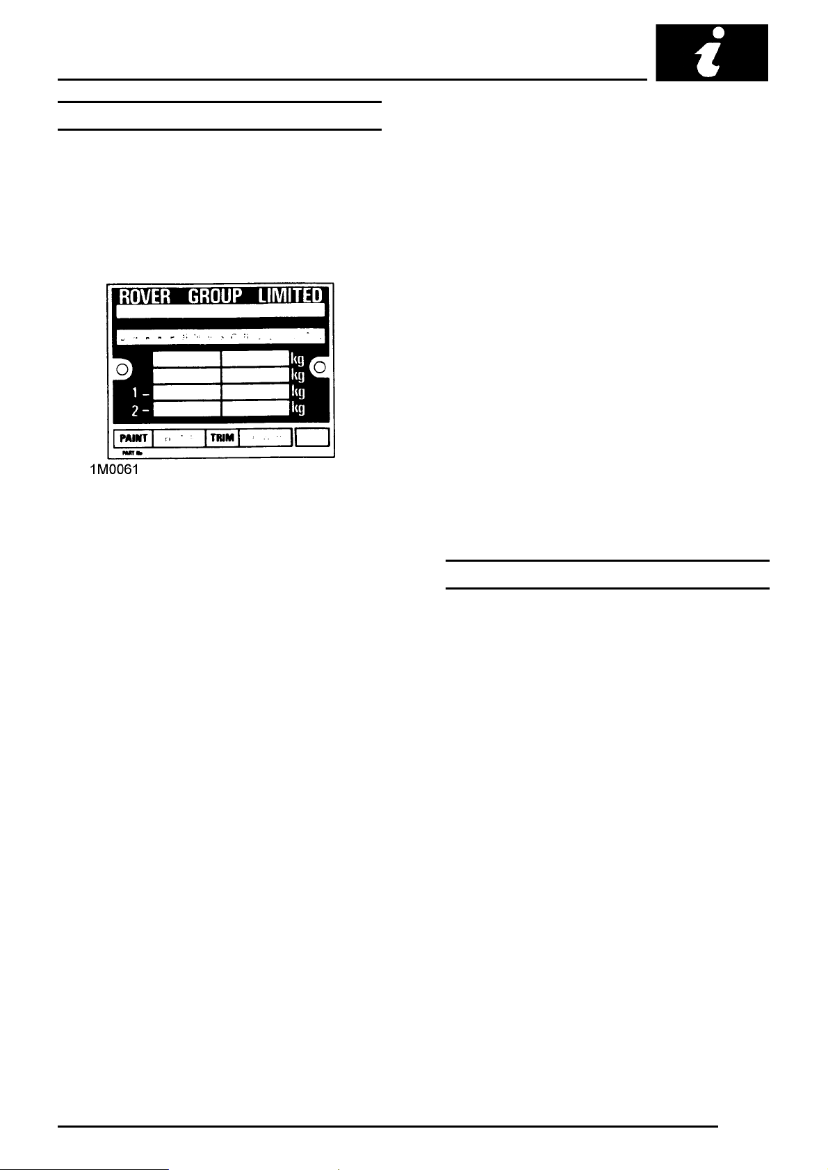
Paint and Trim colour codes
3-letter codes identifying the original Paint and Trim
colours are stamped on the VIN plate.
Paint
Example: H A M
H= Basic colour
A= Mark identifier
M= Colour/Shade name
Trim
Example: L P R
L= Basic colour
P= Mark identifier
R= Colour/Shade name
Vehicle identification number
Example: SAXXNNAZEBD134455
S= Geographic area
A= Country
X= Manufacturer
XN= Marque/Model
N= Class
A= Body
Z= Engine
E= Transmission and Steering
B= Model change
D= Assembly plant
6 figures= Serial number
IDENTIFICATION NUMBER LOCATIONS
Engine number
Stamped on the front face of the cylinder block
adjacent to the alternator.
Gearbox number
Shown on a label attached to the upper face of the
final drive housing.
Body number
The body number is stamped on a plate fixed to the
bonnet locking platform.
VEHICLE IDENTIFICATION NUMBER 1
Page 18

Page 19

GENERAL INFORMATION
GENERAL PRECAUTIONS AND FITTING INSTRUCTIONS
Ignition system safety precautions
WARNING: Before commencing work on
an ignition system, all high tension
terminals, adapters and diagnostic
equipment for testing should be inspected to
ensure that they are adequately insulated and
shielded to prevent accidental personal contacts
and minimise the risk of shock. Wearers of
surgically implanted pacemaker devices should
not be in close proximity to ignition circuits or
diagnostic equipment.
Dangerous substances
WARNING: Many liquids and other
substances used in motor vehicles are
poisonous and should under no
circumstances be consumed and should, as far
as possible, be kept from contact with the skin.
These substances among others include acid,
anti- freeze, asbestos, brake fluid, fuel,
windscreen washer additives, lubricants,
refrigerant and various adhesives.
Always read carefully the instructions printed on
labels or stamped on components and obey
them implicitly. Such instructions are included
for reasons of your health and personal safety.
Never disregard them.
Used engine oils: Prolonged exposure to used
engine oils can cause serious skin disorders,
avoid excessive skin contact and always adhere
to the following recommendations:
Engine oils
Prolonged and repeated contact with mineral oil will
result in the removal of natural fats from the skin,
leading to dryness, irritation and dermatitis. In
addition, used engine oil contains potentially harmful
contaminants which may cause skin cancer.
Adequate means of skin protection and washing
facilities must be provided.
Health Protection Precautions
• Avoid prolonged and repeated contact with oils,
particularly used engine oils.
• Wear protective clothing, including impervious
gloves where practicable.
• Do not put oily rags in pockets.
• Avoid contaminating clothes, particularly
underpants, with oil.
• Overalls must be cleaned regularly. Discard
heavily soiled clothing and oil impregnated
footwear.
• First aid treatment should be obtained
immediately for open cuts and wounds.
• Use barrier creams, applying before each work
period, to help the removal of oil from the skin.
• Wash with soap and water to ensure all oil is
removed (skin cleansers and nail brushes will
help). Preparations containing lanolin replace the
natural skin oils which have been removed.
• Do not use petrol, kerosene, diesel fuel, gas oil,
thinners or solvents for cleaning skin.
• If skin disorders develop, obtain medical advice
without delay.
• Where practicable, degrease components prior
to handling.
• Where there is a risk of eye contact, eye
protection should be worn, for example, chemical
goggles or face shields; in addition an eye wash
facility should be provided.
Environmental Protection Precautions
It is illegal to pour used oil on to the ground, down
sewers or drains, or into water courses.
Burning of used engine oil in small space heaters or
boilers can be recommended only for units of
approved design. The heating system must meet the
regulatory standards of HMIP for small burners of
less than 0.4 MV. If in doubt check with the
appropriate local authority and/or manufacturer of
approved appliance.
Dispose of used oil and used filters through
authorised waste disposal contractors to licensed
waste disposal sites, or to the waste oil reclamation
trade. If in doubt, contact the Local Authority for
advice on disposal facilities.
GENERAL PRECAUTIONS AND FITTING INSTRUCTIONS 1
Page 20

GENERAL INFORMATION
SAFETY INSTRUCTIONS
Jacking
The recommended jacking points are given in
LIFTING AND TOWING, always ensure that any
lifting apparatus has adequate load and safety
capacity for the weight to be lifted. Ensure the
vehicle is standing on level ground prior to lifting or
jacking. Apply the handbrake and chock the wheels.
Never rely on a jack as the sole means of support
when working beneath the vehicle. Use additional
safety supports beneath the vehicle.
Do not leave tools, lifting equipment, spilt oil, etc.
around or on the work bench area.
Precautions against damage
Always fit wing and seat covers before commencing
work. Avoid spilling brake fluid or battery acid on
paintwork. Wash off with water immediately if this
occurs.
Disconnect the battery earth lead before starting
work, see ELECTRICAL PRECAUTIONS.
Always use the recommended service tool or a
satisfactory equivalent where specified.
Protect exposed bearing and sealing surfaces and
screw threads from damage.
Brake shoes and pads
WARNING: Always fit the correct grade
and specification of brake linings and
renew brake pads and brake shoes in axle
sets only.
Brake hydraulics
WARNING: It is imperative that the correct
brake fittings are used and that threads of
components are compatible.
Always use two spanners when slackening or
tightening brake pipe or hose connections. Ensure
that hoses run in a natural curve and are not kinked
or twisted. Fit brake pipes securely in their retaining
clips and ensure that the pipe run cannot contact a
potential chafing point.
Containers used for hydraulic fluid must be kept
absolutely clean. Do not store hydraulic fluid in an
unsealed container, it will absorb water and in this
condition would be dangerous to use. Do not allow
hydraulic fluid to be contaminated with mineral oil, or
use a container which has previously contained
mineral oil. Do not re-use fluid from the system.
Always use clean brake fluid or a recommended
alternative to clean hydraulic components. Fit a
blanking cap to an hydraulic union and a plug to its
socket after removal to prevent the ingress of dirt.
Absolute cleanliness must be observed with
hydraulic components.
Engine coolant caps and plugs
Extreme care is necessary when removing engine
coolant caps and plugs when the engine is hot and
especially if it is overheated. To avoid the possibility
of scalding allow the engine to cool before
attempting coolant cap or plug removal.
Cleaning components
Always use the recommended cleaning agent or
equivalent.
Do not use degreasing equipment for components
containing items which could be damaged by the
use of this process. Whenever possible clean
components and the area surrounding them before
removal. Always observe scrupulous cleanliness
when cleaning dismantled components.
2
GENERAL PRECAUTIONS AND FITTING INSTRUCTIONS
Page 21
GENERAL INFORMATION
Joints and joint faces
Fit joints dry unless otherwise specified in this
Manual.
If gaskets and/or jointing compound is
recommended for use; remove all traces of old
jointing material prior to reassembly. Do not use a
tool which will damage the joint faces and smooth
out any scratches or burrs on the joint faces using
an oil stone. Do not allow dirt or jointing material to
enter any tapped holes.
Prior to reassembly, blow through any pipes,
channels or crevices with compressed air.
Screw threads
Both UNF and metric threads to ISO standards are
used.
Damaged nuts, bolts and screws must always be
discarded.
Cleaning up damaged threads with a die or tap
impairs the strength and closeness of fit of the
threads and is not recommended.
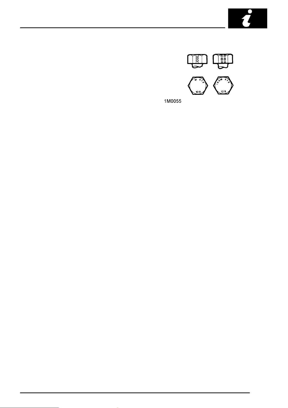
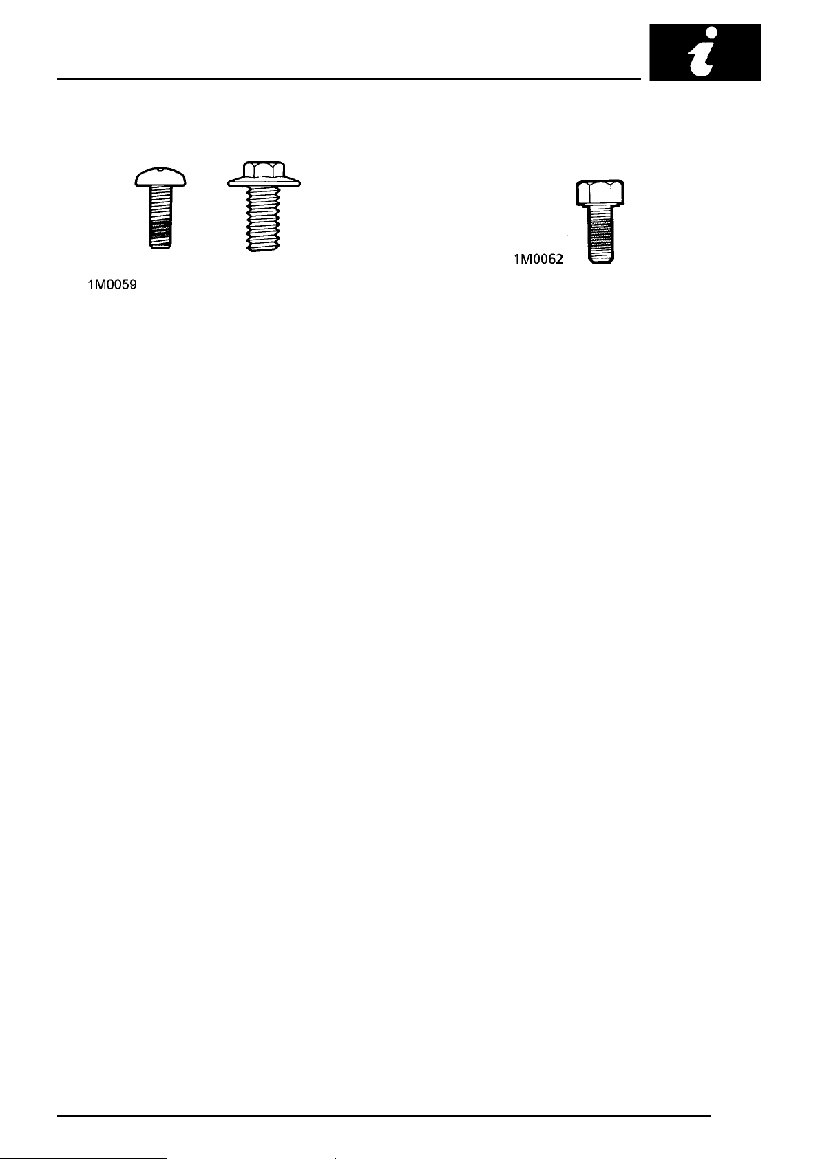
Bolt identification
An ISO metric bolt or screw made of steel and larger
than 6 mm in diameter can be identified by either of
the symbols ISO M or M embossed or indented on
top of the head.
In addition to marks to identify the manufacturer, the
head is also marked with symbols to indicate the
strength grade, e.g. 8.8; 10.9; 12.9; 14.9. As an
alternative, some bolts and screws have the M and
strength grade symbol on the flats of the hexagon.
Castellated nuts must not be slackened back to
accept a split-pin, except in those recommended
cases when this forms part of an adjustment.
Do not allow oil or grease to enter blind threaded
holes. The hydraulic action on screwing in the bolt or
stud could split the housing.
Always tighten a nut or bolt to the recommended
torque figure. Damaged or corroded threads can
affect the torque reading.
To check or re-tighten a bolt or screw to a specified
torque figure, first slacken a quarter of a turn, then
retighten to the correct torque figure.
GENERAL PRECAUTIONS AND FITTING INSTRUCTIONS 3
Page 22
GENERAL INFORMATION
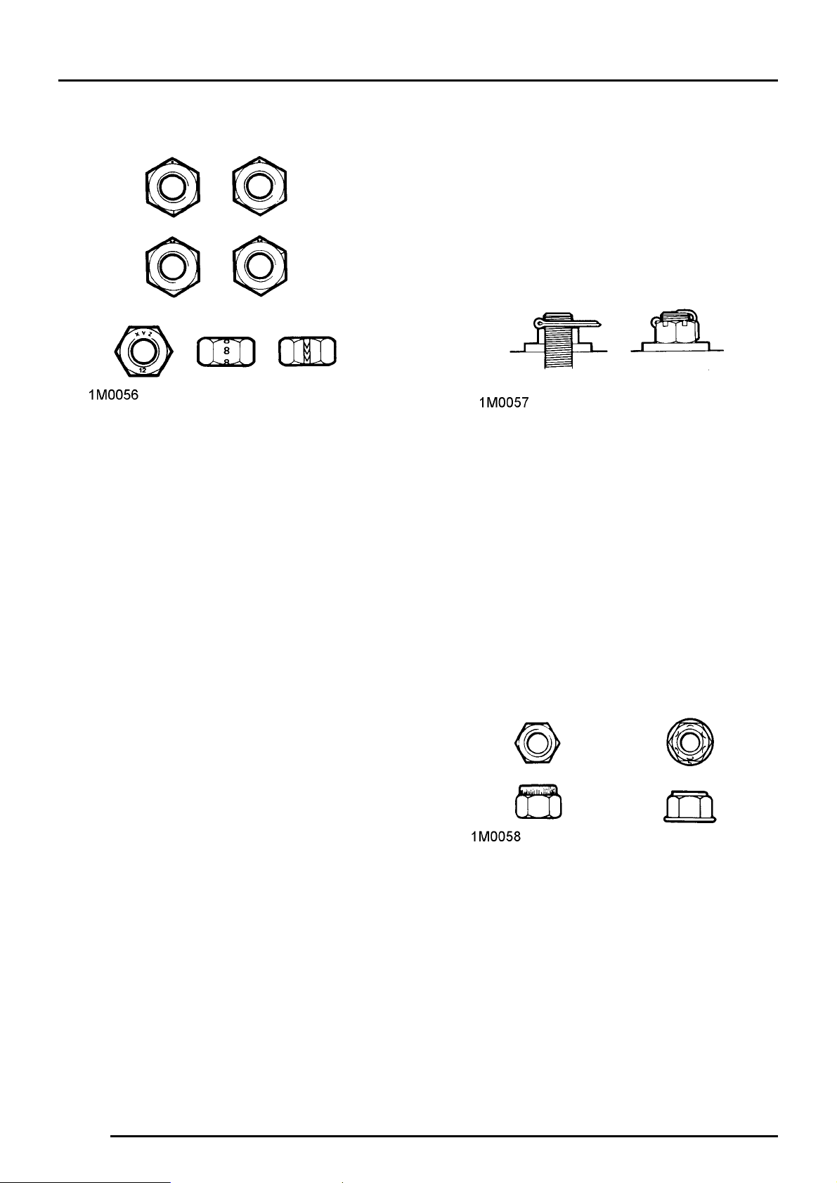
Nut identification
A nut with an ISO metric thread is marked on one
face or on one of the flats of the hexagon with the
strength grade symbol 8, 12, or 14. Some nuts with
a strength grade 4, 5 or 6 are also marked and some
have the metric symbol M on the flat opposite the
strength grade marking.
A clock face system is used as an alternative
method of indicating the strength grade. The
external chambers or a face of the nut is marked in a
position relative to the appropriate hour mark on a
clock face to indicate the strength grade.
A dot is used to locate the 12 o’clock position and a
dash to indicate the strength grade. If the grade is
above 12, two dots identify the 12 o’clock position.
Locking devices
Always release locking tabs and fit new locking
washers, do not re-use locking tabs. Always use a
backing spanner when slackening or tightening
brake and fuel pipe unions.
Fitting a split pin
Always fit new split-pins of the correct size for the
hole in the bolt or stud. Do not slacken back nut to
enter split-pin.
Always fit new roll pins of an interference fit in the
hole.
Always fit new circlips of the correct size for the
groove.
Self-locking nuts
Self-locking nuts, i.e. nylon insert or metal stiff nuts
can be re-used providing resistance can be felt
when the locking portion of the nut passes over the
thread of the bolt or stud.
4
GENERAL PRECAUTIONS AND FITTING INSTRUCTIONS
Page 23
GENERAL INFORMATION
Self-locking bolts and screws
Self-locking bolts and screws, i.e. nylon patched or
trilobular thread can be re-used providing resistance
can be felt when the locking portion enters the
female thread.
Nylon patched bolts and screws have a locking
agent pre-applied to the threads. They are identified
by the presence of a coloured section of thread
which extends for up to 180° around the thread.
Trilobular i.e. Powerlok bolts have a special thread
form which creates a slight interference in the
tapped hole or threads of the nut into which it is
screwed.
DO NOT re-use self-locking fasteners in critical
locations eg engine bearings flywheel. Always use
the correct replacement self-locking nut, bolt or
screw.
DO NOT fit non self-locking fasteners in applications
where a self-locking nut, bolt or screw is specified.
Encapsulated bolts and screws
Encapsulated bolts and screws have a
micro-encapsulated locking agent pre-applied to the
thread. They are identified by the presence of a
coloured section of thread which extends completely
around the thread - 360°. The locking agent is
released and activated by the assembly process and
is then chemically cured to provide the locking
action.
Unless a specific repair procedure states otherwise,
encapsulated bolts may be re-used providing the
threads are undamaged and the following procedure
is adopted.
Remove loose adhesive from the bolt and housing
threads, ensure threads are clean and free of oil and
grease. Apply an approved adhesive.
Fit a new encapsulated bolt, or if not available a bolt
of equivalent specification treated with an approved
adhesive.
GENERAL PRECAUTIONS AND FITTING INSTRUCTIONS 5
Page 24

GENERAL INFORMATION
Oil seals
Always renew oil seals which have been removed
from their working location either as an individual
component or as part of an assembly.
Ensure the surface on which the new seal is to run is
free of burrs or scratches. Renew the component if
the original sealing surface cannot be completely
restored.
Protect the seal from any surface which it has to
pass when being fitted. Use a protective sleeve or
tape to cover the relevant surface.
Lubricate the sealing lips with a recommended
lubricant before use to prevent damage in initial use.
On dual lipped seals, smear the area between the
lips with grease.
Use the recommended service tool to fit an oil seal.
If the correct service tool is not available, use a
suitable tube approximately 0.4 mm smaller than the
outside diameter of the seal.
Body repairs
Any damage found, that would affect the corrosion
resistance of the vehicle during the Warranty period
must be rectified by an authorised Rover Dealer to
the standards, and by the methods, detailed in the
Body Repair Manual.
Replacement body panels
Body panels are supplied coated in cathodic
electrocoat primer.
Synthetic rubber
Many ’O’ rings, seals, hoses, flexible pipes and other
similar items which appear to be natural rubber, are
in fact, made of synthetic materials called
Fluoroelastomers. Under normal operating
conditions this material is safe and does not present
a health hazard. However, if the material is
damaged by fire or excessive heating, it can break
down and produce highly corrosive Hydrofluoric acid
which can cause serious burns on contact with skin.
If skin contact does occur:
Press or drift the seal in to the depth of its housing,
with the sealing lip facing the lubricant to be retained
if the housing is shouldered, or flush with the face of
the housing where no shoulder is provided.
Service tools and garage equipment
Special service tools have been developed to
facilitate removal, dismantling and assembly of
mechanical components in a cost effective and
practical manner without causing damage. Some
operations in this Manual cannot be carried out
without the aid of the relevant service tools.
TestBook
TestBook is a computerised workshop tool which
provides your dealership with instant access to the
very latest Technical Information from ROVER,
allowing for accurate and effective fault diagnosis
and repair of all Rover Vehicles.
Where specific garage equipment is required for
diagnosis and repair, reference should be made to
the Service Tools and Equipment Programme where
details of the equipment recommended by Rover
Service may be found.
• Remove any contaminated clothing immediately.
• Irrigate effected area with a copious amount of
cold water or limewater for 15 to 60 minutes.
• Obtain medical assistance immediately
Should the material be in a burnt or over-heated
condition handle only with seamless industrial
gloves. Decontaminate and dispose of loves
immediately after use.
6
GENERAL PRECAUTIONS AND FITTING INSTRUCTIONS
Page 25

GENERAL INFORMATION
FUEL HANDLING PRECAUTIONS
General
The following information provides basic precautions
which must be observed if petrol (gasoline) is to be
handled safely. It also outlines other areas of risk
which must not be ignored. This information is
issued for basic guidance only, and if in doubt
appropriate enquiries should be made of your local
Fire Officer.
Petrol - Gasoline
Petrol/gasoline vapour is highly flammable and in
confined spaces is also explosive and toxic.
When petrol/gasoline evaporates it produces 150
times its own volume in vapour which when diluted
with air becomes a readily ignitable mixture. The
vapour is heavier than air and will always fall to the
lowest level. It can readily be distributed throughout
a workshop by air currents; consequently, even a
small spillage of petrol/ gasoline is potentially very
dangerous.
Always have a fire extinguisher containing FOAM,
CO2, GAS or POWDER close at hand when
handling or draining fuel or when dismantling fuel
systems and in other areas where fuel containers
are stored.
Always disconnect the vehicle battery before
carrying out dismantling or draining work on a fuel
system.
Fuel tank drainage
WARNING: Petrol/gasoline must not be
extracted or drained from any vehicle
whilst it is standing over a pit.
Draining or extraction of petrol/gasoline from a
vehicle fuel tank must be carried out in a well
ventilated area.
The receptacle used to contain the
petrol/gasoline must be more than adequate for
the full amount of fuel to be extracted or drained.
The receptacle should be clearly marked with its
contents, and placed in a safe storage area
which meets the requirements of local authority
regulations.
CAUTION: When petrol/gasoline has been
extracted or drained from a fuel tank the
precautions governing naked lights and
ignition sources should be maintained.
Fuel tank removal
When the fuel line is secured to the fuel tank outlet
by a spring steel clip, the clip must be released
before the fuel line is disconnected or the fuel tank is
removed. This procedure will avoid the possibility of
residual petrol fumes in the fuel tank being ignited
when the clip is released.
As an added precaution fuel tanks should have a
’PETROL (GASOLINE) VAPOUR’ warning label
attached to them as soon as they are removed from
the vehicle.
Whenever petrol/gasoline is being handled, drained
or stored or when fuel systems are being
dismantled, all forms of ignition must be
extinguished or removed; any leadlamps must be
flameproof and kept clear of spillage.
WARNING: No one should be permitted to
repair components associated with
petrol/gasoline without first having
specialist training.
FUEL HANDLING PRECAUTIONS 1
Page 26

GENERAL INFORMATION
Fuel tank repairs
Under no circumstances should a repair to any fuel
tank involving heat treatment be carried out without
first rendering the tank SAFE, by using one of the
following methods:
a. STEAMING: With the filler cap and tank unit
removed, empty the tank. Steam the tank for at least
two hours with low pressure steam. Position the tank
so that condensation can drain away freely, ensuring
that any sediment and sludge not volatized by the
steam is washed out during the steaming process.
b. BOILING: With the filler cap and tank unit
removed, empty the tank. Immerse the tank
completely in boiling water containing an effective
alkaline degreasing agent or a detergent, with the
water filling and also surrounding the tank for at least
two hours.
After steaming or boiling, a signed and dated label to
this effect should be attached to the tank.
Body and chassis repairs
When a body or chassis repairs involve the use of
heat, all fuel pipes which run in the vicinity of the
repair area must be removed, and the tank outlet
plugged, BEFORE HEAT IS APPLIED. If the repair
is in the vicinity of the fuel tank, the tank must be
removed.
Plastic fuel pipes are particularly susceptible to heat,
even at relatively low temperature, and can be
melted by heat conducted from some distance away.
Fuel lines or tanks must not be removed whilst the
vehicle is over an inspection pit.
2
FUEL HANDLING PRECAUTIONS
Page 27

GENERAL INFORMATION
ELECTRICAL PRECAUTIONS
General
The following guidelines are intended to ensure the
safety of the operator whilst preventing damage to
the electrical and electronic components fitted to the
vehicle. Where necessary specific precautions are
detailed in the relevant sections of this Manual which
should be referred to prior to commencing repair
operations.
Equipment - Prior to commencing any test
procedure on the vehicle ensure that the relevant
test equipment is working correctly and any harness
or connectors are in good condition, this particularly
applies to mains lead and plugs.
WARNING: Before commencing work on
an ignition system all high tension
terminals, adapters and diagnostic
equipment for testing should be inspected to
ensure that they are adequately insulated and
shielded to prevent accidental personal contacts
and minimise the risk of shock. Wearers of
surgically implanted pacemaker devices should
not be in close proximity to ignition circuits or
diagnostic equipment.
Polarity - Never reverse connect the vehicle battery
and always observe the correct polarity when
connecting test equipment.
High Voltage Circuits - Whenever disconnecting live
ht circuits always use insulated pliers and never
allow the open end of the ht lead to come into
contact with other components particularly ECU’s.
Exercise caution when measuring the voltage on the
coil terminals while the engine is running, high
voltage spikes can occur on these terminals.
Having confirmed a component to be faulty switch
off the ignition and disconnect the battery. Remove
the component and support the disconnected
harness. When replacing the component keep oily
hands away from electrical connection areas and
push connectors home until any locking tabs fully
engage.
Battery disconnection
Before disconnecting the battery, switch off all
electrical equipment. If the radio is to be serviced,
ensure the security code has been deactivated.
CAUTION: To prevent damage to electrical
components ALWAYS disconnect the
battery when working on the vehicle
electrical system. The earth lead must be
disconnected first and reconnected last.
Always ensure that battery leads are routed
correctly and are not close to any potential
chafing points.
Battery charging
Recharge the battery out of the vehicle and keep the
top well ventilated. While being charged or
discharged, and for approximately fifteen minutes
afterwards, batteries emit hydrogen gas. This gas is
inflammable.
Always ensure any battery charging area is well
ventilated and that every precautions is taken to
avoid naked flames and sparks.
Connectors and Harness - The engine compartment
of a vehicle is a particularly hostile environment for
electrical components and connectors. Always
ensure these items are dry and oil free before
disconnecting and connecting test equipment. Never
force connectors apart either by using tools or by
pulling on the wiring harness. Always ensure locking
tabs are disengaged before removal and not
orientation to enable correct reconnection. Ensure
that any protective covers and substances are
replaced if disturbed.
ELECTRICAL PRECAUTIONS 1
Page 28

GENERAL INFORMATION
Disciplines
Switch off ignition prior to making any connection or
disconnection in the system as electrical surge
caused by disconnecting ’live’ connections can
damage electronic components.
Ensure hands and work surfaces are clean and free
of grease, swarf, etc. as grease collects dirt which
can cause tracking or high-resistance contacts.
When handling printed circuit boards, treat them as
you would a disc - hold by the edges only; note that
some electronic components are susceptible to body
static.
Connectors should never be subjected to forced
removal or refit, especially inter-board connectors,
damaged contacts will cause short- circuit and
open-circuit conditions.
Prior to commencing test, and periodically during
test, touch a good earth, i.e. cigar lighter socket, to
discharge body static as some electronic
components are vulnerable to static electricity.
Grease for electrical connectors
All under bonnet and under body connectors are
protected against corrosion by the application of a
special grease on production. Should connectors be
disturbed in service or repaired or replaced, a
grease of this type, available in 150 gm tubes under
Part No. BAU 5811, should again be applied.
NOTE: The use of other greases must be
avoided as they can migrate into relays,
switches etc. contaminating the contacts
and leading to intermittent operation or failure.
2
ELECTRICAL PRECAUTIONS
Page 29

INFORMATION
CONTENTS
LIFTING AND TOWING
JACKING, SUPPORTING AND TOWING 1................................................................
WORKSHOP JACK 2..................................................................................................
WHEEL-FREE LIFT 2..................................................................................................
TOWING 2...................................................................................................................
GENERAL DATA
ENGINE 1....................................................................................................................
FUEL SYSTEM 1.........................................................................................................
COOLING SYSTEM 1..................................................................................................
CLUTCH 2...................................................................................................................
MANUAL GEARBOX 2................................................................................................
AUTOMATIC GEARBOX 2..........................................................................................
FINAL DRIVE 2............................................................................................................
WHEELS 3...................................................................................................................
TYRE SIZE 3...............................................................................................................
TYRE PRESSURES 3.................................................................................................
ELECTRICAL 3............................................................................................................
DIMENSIONS 4...........................................................................................................
WEIGHTS 4.................................................................................................................
Page
ENGINE TUNING DATA
Model: SPi with manual gearbox 1..............................................................................
Model: SPi with automatic gearbox 2...........................................................................
Model: MPi 3................................................................................................................
TORQUE WRENCH SETTINGS
GENERAL 1.................................................................................................................
ENGINE 1....................................................................................................................
EMISSION CONTROL 2..............................................................................................
ENGINE MANAGEMENT SYSTEM 2..........................................................................
FUEL SYSTEM 2.........................................................................................................
COOLING 2.................................................................................................................
MANIFOLD AND EXHAUST 3.....................................................................................
CLUTCH 3...................................................................................................................
MANUAL GEARBOX 3................................................................................................
STEERING 3...............................................................................................................
SUSPENSION 4..........................................................................................................
BRAKES 4...................................................................................................................
RESTRAINT SYSTEMS 4...........................................................................................
BODY 5........................................................................................................................
HEATING AND VENTILATION 5.................................................................................
WIPERS AND WASHERS 5........................................................................................
ELECTRICAL 5............................................................................................................
INSTRUMENTS 5........................................................................................................
CAPACITIES, FLUIDS AND LUBRICANTS
CAPACITIES 1.............................................................................................................
FLUIDS 1.....................................................................................................................
LUBRICATION 2..........................................................................................................
Page 30

Page 31

JACKING, SUPPORTING AND TOWING
INFORMATION
Jacking and support points
1. Lashing/towing eye - front
2. LH floor front reinforcement
3. RH floor front reinforcement
4. Sill reinforced brackets - front
5. LH subframe longitudinal - front
WARNING: In accordance with normal
workshop practice and to avoid the
possibility of damage or personal injury,
work must not be carried out on or under a
vehicle when it is supported solely on a jack.
Place safety supports under the sill reinforced
brackets (4 and 7).
6. RH subframe longitudinal - front
7. Sill reinforced brackets - rear
8. RH subframe longitudinal - rear
9. LH subframe longitudinal - rear
10. Lashing eye - rear
WARNING: Do not position a jack, jack
stand or wheel free support under the
subframe transverse members.
CAUTION: Use suitable hardwood or
rubber pads when jacking and supporting
the vehicle.
LIFTING AND TOWING 1
Page 32

INFORMATION
WORKSHOP JACK
Front
Locate the jack head under the front subframe
longitudinal (5 or 6) towards the rear directly below
the drive shaft.
Position a safety support under the appropriate floor
front reinforcement (2 or 3).
Side
Locate the jack head under the appropriate front sill
reinforced bracket (4).
Position a safety support under the nearest floor
front reinforcement (2 or 3).
CAUTION: The side jacking points are
designed to accommodate the vehicle jack
only.
Rear
Locate the jack head under the triangular depression
on the appropriate rear subframe longitudinal (8 or
9).
Position a safety support under the adjacent rear sill
reinforcement (7).
WHEEL-FREE LIFT
TOWING
It is recommended that a recovery trailer or two
wheel car ambulance be used. When a recovery
trailer, the car should be secured using the front
lashing/towing eye (1) and the rear lashing points on
the subframe (10). No other attachment points may
be used for this purpose. In an emergency, the car
may be towed on its own wheels using the front
lashing/towing eye.
CAUTION: Do not use the car for towing
another light vehicle, or a trailer, as it not
suitable for this purpose.
Suspended tow
A front wheel lift should be used with a cross beam
and body protection.
Before towing commences release the handbrake,
place the gear lever in neutral and the ignition switch
at ’I’. Do not tow at a speed greater than 30 mph, 50
km/h.
CAUTION: On no account should the car
be towed with the front wheels on the
ground if the transmission is faulty, the
transmission fluid level is low, or the towing
distance exceeds 30 miles, 50 km.
Two-post lift and crossbeams: Locate the pads
under the floor front reinforcements (2, 3), and under
the rear sill reinforcements (5, 7).
Longitudinal beams: Locate the beams under the
front and rear subframe longitudinals (5, 6) and (8,
9). Raise the lift a few inches and ensure the car is
firmly supported. Raise the lift to full height and
inspect the lifting points for security.
2
LIFTING AND TOWING
Page 33

Manual gearbox models
Use the front lashing/towing eye (1) for towing the
car on all four wheels from the front.
WARNING: To ensure that the steering
does not lock when the car is being towed,
it is essential that the starter key is turned
to position ’I’, and remains there while the car is
moving.
Ensure the following precautions are observed:
Do not tow if the gearbox or a drive shaft is
faulty.
Do not tow if a wheel or drive shafts are touching
the body or frame.
Ensure the gear lever is in neutral and the
handbrake is released.
Remember that greater effort than normal will be
necessary to apply the brakes if the car is being
towed without the engine running.
Automatic gearbox models
When a car with an automatic gearbox is to be
towed, a suspended tow must be used because the
gearbox is not adequately lubricated without the
engine running. The following precautions must be
observed:
INFORMATION
The selector must be at ’N’.
CAUTION: A rear suspended tow must not
be attempted as serious damage will be
caused to the automatic transmission.
NOTE: A vehicle fitted with an automatic
gearbox cannot be started by towing or
pushing.
LIFTING AND TOWING 3
Page 34

Page 35

ENGINE
Type 8 valve OHV......................................
Cylinder arrangement 4 in line - transverse........................
Bore 70.61 mm......................................
Stroke 81.28 mm....................................
Capacity 1275 cm
Firing order 1 - 3 - 4 - 2................................
Rotation Clockwise, viewed from front of engine...................................
Compression ratio 10.0: 1...........................
Valve timing
Inlet:
Opens 9°BTDC...................................
Closes 41°ABDC...................................
Exhaust:
Opens 55°BBDC...................................
Closes 17°ATDC...................................
Lubrication
System type Wet sump, crankshaft driven eccentric rotor pump................................
Relief valve opening pressure 2.0 bar..................
Pressure at idle 0.5 bar.............................
Oil pressure warning light switch opens 0.2 to 0.3 bar..........
Oil filter Full flow with disposable canister...................................
...................................
INFORMATION
3
FUEL SYSTEM
Electronic fuel injection data See Engine Tuning Data...................
Fuel Pump:
Type Electric immersible.....................................
Pump maximum pressure at 16V 2.7 bar..............
Regulated injection pressure range 1.0 to 3.0 bar ± 0.2 bar.............
COOLING SYSTEM
Pressure cap opens 0.5 bar..........................
Thermostat starts to open 88°C ± 2°.....................
Thermostat fully open 100°C ± 2°........................
Cooling fan operation:
On 105°C......................................
Off 98°C......................................
GENERAL DATA 1REVISED: 12/96
Page 36

INFORMATION
CLUTCH
Type Diaphragm spring, hydraulically operated......................................
Clutch plate diameter 180 mm.........................
MANUAL GEARBOX
Gear ratios:
Fourth 1.000 : 1...................................
Third 1.425 : 1....................................
Second 2.185 : 1..................................
First 3.647 : 1.....................................
Reverse 3.667 : 1..................................
AUTOMATIC GEARBOX
Type 3-speed, torque converter......................................
Gear ratios:
Drive 1.000 : 1....................................
Third 1.460 : 1....................................
Second 1.845 : 1..................................
First 2.690 : 1.....................................
Reverse 2.690 : 1..................................
FINAL DRIVE
Manual gearbox:
Ratio 3.213 : 1....................................
Road speed at 1000 rev/min:
Fourth 28.6 km/h................................... 17.8 mph
Third 20.1 km/h.................................... 12.5 mph
Second 13.1 km/h.................................. 8.2mph
First 7.9 km/h..................................... 4.9mph
Automatic gearbox:
Ratio 2.690 : 1....................................
Road speed at 1000 rev/min:
Drive 29.3 km/h.................................... 18.2 mph
Third 20.1 km/h.................................... 12.5 mph
Second 15.9 km/h.................................. 9.9mph
First 10.1 km/h..................................... 6.8mph
2
GENERAL DATA
Page 37

WHEELS
Wheel size and type:
Steel wheel (spare only) 4«J x 12.....................
Standard alloy wheel 4«J x 12........................
Optional alloy wheel 6J x 13........................
TYRE SIZE
Steel spare wheel 145/70-SR 12...........................
Standard alloy wheel 145/70-SR 12.........................
Optional alloy wheel 175/50-VR 13.........................
TYRE PRESSURES
Pressures (cold):
INFORMATION
Loading conditions bar lbf/in
All load conditions
145/70-SR 12
Front 2.0 28
Rear 2.0 28
175/50-VR 13
Front 2.0 28
Rear 1.8 26
ELECTRICAL
System 12 volt, negative earth....................................
Battery
Cold crank 265 amps.................................
Reserve capacity 45 minutes............................
Alternator
Type A115l - 65......................................
Maximum output 65 Amps............................
Regulator 21TR..................................
Starter motor
Type M79......................................
Power 0.8 kW....................................
GENERAL DATA 3
Page 38

INFORMATION
DIMENSIONS
Overall length 3.05 m..............................
Overall width (including mirrors) 1.58 m................
Overall height * 1.34 m.............................
Ground clearance * 163 mm..........................
Wheelbase 2.04 m.................................
Turning circle (kerb to kerb):
145/70 SR-12 tyres 8.60 m.........................
175/VR-13 tyres 8.80 m............................
* At unladen weight
WEIGHTS
Unladen (fuel tank full, excluding optional fittings) 715 kg...
Maximum gross vehicle weight 1050 kg.................
Maximum roof rack load (distributed) 50 kg............
CAUTION: Do not use the vehicle for towing a trailer, as it is not suitable for this purpose.
4
GENERAL DATA
Page 39

Model: SPi with manual gearbox
INFORMATION
Engine
Type / Capacity 12A2EK71/1275 cm
Firing order 1 - 3 - 4 - 2................................
Compression ratio 10.0: 1...........................
Idle speed, controlled by the ECM * 900 æ 50 rev/min.............
Exhaust gas CO content at idle less than 0.4% hot.................
Ignition timing at idle speed ¸c15°BTDC (nominal)..................
Valve rocker clearance (cold) 0.27 to 0.33 mm..................
Ignition Coil
Type Quad type dry......................................
Part No. NEC 1000710...................................
Primary resistance at 20°C 0.41 to 0.61 ohm....................
Secondary resistance at 20°C 6200 to 6700 ohm..................
Consumption at engine idle speed 4.7 to 6.7 amps..............
Spark Plugs
Type NGK BPR6E......................................
Plug gap 0.80 to 0.90 mm..................................
Engine Management System
Type Single point throttle body injection......................................
MEMS ECM MNE 101350................................
Fuel pump module WFX 10047...........................
Injector/fuel pressure regulator JZX 3300................
Fuel pressure 1.0 æ 0.2 bar constant..............................
Throttle position (TP) sensor MJC 10020...................
Intake air temperature (IAT) sensor NNK 10001..............
Crankshaft position (CKP) sensor ADU 7340...............
Engine coolant temperature (ECT) sensor ADU 7161........
Heated oxygen sensor (HO2S) MHK 10004.................
Lost motion gap at engine idle speed Equal either side of lever............
TP sensor voltage:
Throttle closed 0 to 1v.............................
Throttle open 90° 4to5v...........................
Throttle open 65° 3to4v...........................
Fuel grade 95 RON minimum - UNLEADED fuel.................................
.............................
3
CAUTION: Do not use LEADED fuel as it will damage the catalyst. Serious damage to the engine may
occur if a lower octane number fuel than that recommended is used.
* No electrical load present
¸c Crankshaft degrees and rev/min
ENGINE TUNING DATA 1
Page 40

INFORMATION
Model: SPi with automatic gearbox
Engine
Type / Capacity 12A2EK72/1275 cm
Firing order 1 - 3 - 4 - 2................................
Compression ratio 9.4: 1...........................
Idle speed, controlled by the ECM * 900 æ 50 rev/min.............
Exhaust gas CO content at idle less than 0.4% hot.................
Ignition timing at idle speed ¸c15°BTDC (nominal)..................
Valve rocker clearance (cold) 0.27 to 0.33 mm..................
Ignition Coil
Type Quad type dry......................................
Part No. NEC 1000710...................................
Primary resistance at 20°C 0.41 to 0.61 ohm....................
Secondary resistance at 20°C 6200 to 6700 ohm..................
Consumption at engine idle speed 4.7 to 6.7 amps..............
Spark Plugs
Type NGK BPR6E......................................
Plug gap 0.80 to 0.90 mm..................................
Engine Management System
Type Single point throttle body injection......................................
MEMS ECM MNE 101350................................
Fuel pump module WFX 10047...........................
Injector/fuel pressure regulator JZX 3300................
Fuel pressure 1.0 æ 0.2 bar constant..............................
Throttle position (TP) sensor MJC 10020...................
Intake air temperature (IAT) sensor NNK 10001..............
Crankshaft position (CKP) sensor ADU 7340...............
Engine coolant temperature (ECT) sensor ADU 7161........
Heated oxygen sensor (HO2S) MHK 10004.................
Lost motion gap at engine idle speed Equal either side of lever............
TP sensor voltage:
Throttle closed 0 to 1v.............................
Throttle open 90° 4to5v...........................
Throttle open 65° 3to4v...........................
Fuel grade 95 RON minimum - UNLEADED fuel.................................
.............................
3
CAUTION: Do not use LEADED fuel as it will damage the catalyst. Serious damage to the engine may
occur if a lower octane number fuel than that recommended is used.
* No electrical load present
¸c Crankshaft degrees and rev/min
2
ENGINE TUNING DATA
Page 41

Model: MPi
INFORMATION
Engine
Type / Capacity 12A2LK70/1275 cm
Firing order 1 - 3 - 4 - 2................................
Compression ratio 10.0: 1...........................
Idle speed, controlled by the ECM * 900 æ 50 rev/min.............
Exhaust gas CO content at idle less than 0.4% hot.................
Ignition timing at idle speed ¸c12°BTDC (nominal)..................
Valve rocker clearance (cold) 0.27 to 0.33 mm..................
Ignition Coil
Type Quad type dry......................................
Part No. NEC 1000710...................................
Primary resistance at 20°C 0.41 to 0.61 ohm....................
Secondary resistance at 20°C 6200 to 6700 ohm..................
Consumption at engine idle speed 4.7 to 6.7 amps..............
Spark Plugs
Type NGK BPR6E......................................
Plug gap 0.80 to 0.90 mm..................................
Engine Management System
Type Two point injection......................................
MEMS ECM MNE 104290................................
Fuel pump module WFX 100810...........................
Injector/fuel pressure regulator MKW 10016................
Fuel pressure 3.0 æ 0.2 bar constant..............................
Throttle position (TP) sensor MJC 10020...................
Intake air temperature (IAT) sensor NNK 10001..............
Crankshaft position (CKP) sensor ADU 7340...............
Camshaft position (CMP) sensor NSC100390................
Engine coolant temperature (ECT) sensor MEK 100060........
Heated oxygen sensor (HO2S) MHK 10004.................
TP sensor voltage:
Throttle closed 0 to 1v.............................
Throttle open 90° 4to5v...........................
Throttle open 65° 3to4v...........................
Fuel grade 95 RON minimum - UNLEADED fuel.................................
.............................
3
CAUTION: Do not use LEADED fuel as it will damage the catalyst. Serious damage to the engine may
occur if a lower octane number fuel than that recommended is used.
* No electrical load present
¸c Crankshaft degrees and rev/min
ENGINE TUNING DATA 3
Page 42

Page 43

Refer to the appropriate section heading for component torque figures, e.g.
Road wheel nuts - refer to SUSPENSION,
Exhaust front pipe to manifold - refer to MANIFOLD AND EXHAUST
GENERAL
Bolt M6 10 Nm...................................
Bolt M8 25 Nm...................................
Bolt M10 45 Nm..................................
Bolt M12 80 Nm..................................
1/4 UNC/UNF 9 Nm..............................
5/16 UNC/UNF 25 Nm.............................
3/8 UNC/UNF 40 Nm..............................
7/16 UNC/UNF 75 Nm.............................
1/2 UNC/UNF 90 Nm..............................
5/8 UNC/UNF 135 Nm..............................
INFORMATION
ENGINE
Timing gear cover bolts 16 Nm.......................
Timing gear nuts 90 Nm............................
Timing chain tensioner bolts 22 Nm...................
Cylinder head nuts 34 Nm then a further 34 Nm...........................
Front cover plate bolts 11 Nm........................
Rocker shaft nuts 25 Nm............................
Camshaft thrust plate screws 11 Nm..................
Rocker cover bolts 5 Nm...........................
Crankshaft pulley bolt 150 Nm........................
Engine LH mounting:
Mounting to subframe - nuts 25 Nm..................
Mounting to engine - bolts 25 Nm....................
Engine RH mounting:
Mounting to flywheel housing cover - bolts 18 Nm.......
Mounting to subframe - nuts 22 Nm..................
Engine steady bar upper bolts 22 Nm..................
Engine steady bar lower:
Bar to subframe bolt 40 Nm........................
Bar to flywheel housing bolt 40 Nm...................
Oil pressure gauge sensor 60 Nm....................
Oil pressure relief valve cap 60 Nm...................
Oil pressure switch 25 Nm..........................
Oil pump to engine - bolts 11 Nm.....................
Flywheel housing to engine/gearbox - bolts 25 Nm.......
Earth lead to engine - bolt 10 Nm.....................
Engine to gearbox - nuts and bolts 8 Nm..............
Flywheel to crankshaft - bolt 150 Nm...................
Flywheel housing cover - bolts 10 Nm.................
Engine mounting adaptor plate to engine - bolts 25 Nm....
TORQUE WRENCH SETTINGS 1REVISED: 12/96
Page 44

INFORMATION
EMISSION CONTROL
Oil breather/separator to flywheel housing 18 Nm........
Catalytic converter to tail pipe nuts 9 Nm..............
Catalytic converter to front pipe nuts 45 Nm.............
Emission canister purge valve to body - bolts 9 Nm......
ENGINE MANAGEMENT SYSTEM
ECT sensor to thermostat housing 15 Nm..............
MAP sensor to inlet manifold 6 Nm...................
IAT sensor to inlet manifold 7 Nm....................
TP sensor to throttle body screws 1.5 Nm...............
Throttle housing to inlet mainifold - bolts 8 Nm..........
Throttle pedal nuts 25 Nm...........................
Spark plugs 25 Nm................................
Ignition coil to bracket - bolts 10 Nm...................
HO2S to exhaust manifold 55 Nm.....................
Air cleaner to inlet manifold 7 Nm....................
ECM to mounting bracket 10 Nm.....................
ECM mounting bracket to body 10 Nm.................
IACV to inlet manifold - bolts 7 Nm...................
CMP sensor to engine - bolt 10 Nm...................
CKP sensor to flywheel housing - bolts 6 Nm...........
CKP sensor multiplug to flywheel housing - bolt 3 Nm....
FUEL SYSTEM
Fuel breather valve nut 9 Nm.......................
Fuel pump to fuel tank nuts 9 Nm....................
IFS to bulkhead - screws 2 Nm......................
Fuel filter mounting bracket to body 9 Nm..............
Fuel pipe unions to fuel filter 30 Nm...................
Fuel feed/return pipes to fuel rail 5 Nm................
Fuel rail to inlet manifold - bolts 10 Nm.................
COOLING
Radiator brackets to bonnet platform 9 Nm.............
Thermostat housing bolts 11 Nm.....................
Coolant pump bolts 22 Nm..........................
Coolant pump pulley bolts 10 Nm.....................
Expansion tank to mounting bracket 10 Nm.............
Expansion tank mounting bracket to body 10 Nm.........
2
TORQUE WRENCH SETTINGS REVISED:12/96
Page 45

MANIFOLD AND EXHAUST
Front pipe to manifold nuts 22 Nm....................
Front pipe to differential housing 22 Nm................
Inlet and exhaust manifold nuts 22 Nm.................
Catalytic converter to tail pipe nuts 9 Nm..............
Catalytic converter to front pipe nuts 45 Nm.............
CLUTCH
Flywheel centre bolt 150 Nm..........................
Pressure plate to flywheel bolts 25 Nm.................
Flywheel housing to engine block bolts 25 Nm...........
Slave cylinder to mounting bracket 37 Nm..............
Slave cylinder mounting bracket to flywheel
housing:
M8 bolts 37 Nm..................................
M5 bolt 7 Nm...................................
Pipe union to master cylinder 14 Nm..................
Pipe union to slave cylinder 14 Nm....................
INFORMATION
MANUAL GEARBOX
Gearbox to engine bolts 28 Nm......................
Third motion shaft bearing retaining bolts 18 Nm.........
First motion shaft gear nut 200 Nm.....................
Speedometer drive housing to gearbox - bolts 25 Nm.....
Speedometer drive housing cover - bolts 8 Nm.........
Speedometer drive pinion clamping plate - bolt 8 Nm.....
STEERING
Steering wheel nut 49 Nm...........................
Drivers air bag module Torx screws 9 Nm.............
Steering column upper mounting to fascia rail bolt 25 Nm..
Inner column to steering rack pinion clamp bolt 16 Nm....
Track rod ball joint to steering arm nut 30 Nm...........
Steering rack U-bolts 15 Nm.........................
Steering rack pinion cover bolts 15 Nm.................
Steering arm to front hub bolts 45 Nm.................
Steering column to pinion - bolt 15 Nm.................
TORQUE WRENCH SETTINGS 3REVISED: 12/96
Page 46

INFORMATION
SUSPENSION
Wheel nuts:
Alloy wheels 50 Nm...............................
Steel wheels 60 Nm..............................
Upper arm to front hub 52 Nm.......................
Lower arm to front hub 52 Nm.......................
Front hub to drive shaft - nut 260 Nm...................
Front subframe turret bolts 67 Nm....................
Front damper to body bracket - nut 37 Nm..............
Front damper to upper arm - nut 48 Nm................
Front subframe to body - nuts and bolts 25 Nm..........
Rear damper to body 25 Nm.........................
Rear damper to suspension arm 25 Nm................
BRAKES
Bleed screw to caliper 9 Nm........................
Brake master cylinder nuts 25 Nm....................
Brake servo banjo bolt 50 Nm........................
Brake servo to bracket nuts 25 Nm....................
Brake servo bracket nuts and bolts to body 25 Nm........
Brake caliper to swivel hub bolts 52Nm................
Brake disc to drive flange bolts 57 Nm.................
Brake drum back plate to radius arm bolts 28 Nm........
Pressure limiting valve to body bolt 17 Nm..............
Brake pipe to master cylinder - union 14 Nm............
Brake drum to hub - screw 7 Nm....................
Brake pipe union to pressure reducing valve 14 Nm.......
Pressure reducing valve to body - bolt 17Nm...........
Brake pedal pivot bolt - nut 15 Nm....................
Brake light switch bracket to pedal box 5 Nm...........
Brake hose union to caliper 15 Nm....................
Brake pipe unon to wheel cylinder 14 Nm...............
RESTRAINT SYSTEMS
Rotary coupler bolts 15 Nm..........................
Diagnostic unit 9 Nm..............................
Airbag module screws 7 Nm........................
Diagnostic harness earth lead bolt 10 Nm..............
Front seat belt stalk bolt 32 Nm......................
Front seat belt upper mounting bolt 32 Nm..............
Front seat belt lower mounting bolt 30 Nm..............
Front seat belt upper mounting bolt 30 Nm..............
Seat belt pre-tensioner reel bolt 30 Nm.................
Seat belt pre-tensioner tube nut 6 Nm................
Seat belt pre-tensioner tube screw 1.2 Nm..............
Rear seat belt buckle to body - bolt 30 Nm..............
Rear seat belt reel to body - bolt 30 Nm................
Rear seat belt lower mounting bolt 30 Nm..............
Rear seat belt upper mounting bolt 30 Nm..............
4
TORQUE WRENCH SETTINGS REVISED:12/96
Page 47

BODY
Bonnet hinge nuts 9 Nm...........................
Front/Rear bumper to body - nuts 10 Nm...............
Door striker to body - screws 18 Nm...................
Bonnet latch to body - bolts 9 Nm....................
Wheel arch extension to body - nuts 9 Nm.............
Fascia top rail to body - nuts 9 Nm...................
Front seat to body - nut and bolt 25 Nm................
HEATING AND VENTILATION
Heater to bulkhead - nut 9 Nm......................
INFORMATION
WIPERS AND WASHERS
Wiper wheel boxes to body - nut 10 Nm................
ELECTRICAL
Alternator pulley nut 25 Nm..........................
Auxiliary drive belt tensioner pulley nut 25 Nm...........
Auxiliary drive belt tensioner to engine 22 Nm...........
Starter motor to flywheel housing bolts 37 Nm...........
Starter solenoid terminal nuts 4 Nm..................
Horn mounting bracket to body 9 Nm.................
Horn to mounting bracket 10 Nm.....................
INSTRUMENTS
Oil temperature gauge sensor 60 Nm..................
TORQUE WRENCH SETTINGS 5ISSUED: 12/96
Page 48

Page 49

CAPACITIES
Fuel tank 34.0 litres..................................
Engine/gearbox oil refill and filter change 4.8 litres.........
Automatic gearbox 5.1 litres...........................
Cooling system refill 4.0 litres.........................
Windscreen washer reservoir 2.3 litres..................
FLUIDS
Fuel
Octane rating: UNLEADED fuel - 95 RON minimum..............................
CAUTION: Catalyst equipped vehicles MUST NOT be run on LEADED fuel as damage to the catalyst
will result.
Brake/Clutch Fluid
INFORMATION
For topping-up Rover recommend the use of AP
New Premium Super DOT 4 brake fluid or Castrol
Universal DOT 4 brake/clutch fluid.
Anti-freeze solutions
The overall anti-freeze concentration should not fall,
by volume below 30% to ensure that the
anti-corrosion properties of the coolant are
maintained. Anti-freeze concentrations greater than
60% are not recommended as cooling efficiency will
be impaired.
Use UNIPART SUPERPLUS 3 ANTI-FREEZE AND
SUMMER COOLANT to protect the cooling system.
If this is not available, use an ethylene glycol based
anti-freeze, containing no methanol with
non-phosphate corrosion inhibitors suitable for use
in mixed metal engines to ensure the protection of
the cooling system against frost and corrosion.
CAUTION: No other ’universal’ anti-freeze
should be used with UNIPART
SUPERPLUS 3 ANTI-FREEZE AND
SUMMER COOLANT.
The cooling system should be drained, flushed and
refilled with the correct amount of anti-freeze
solution at three years and every two years
thereafter.
After filling with anti-freeze solution, attach a warning
label to a prominent position on the vehicle stating
the type of anti-freeze contained in the cooling
system to ensure that the correct type is used for
topping-up.
The recommended quantities of anti-freeze for
different degrees of frost protection are:
Solution Amount of anti-freeze Commences freezing Frozen solid
50% Litres °C °F °C °F
331/
3
50 1.8 -36 - 33 - 48 - 53
1.2 -19 - 2 - 36 - 33
CAPACITIES, FLUIDS AND LUBRICANTS 1
Page 50

INFORMATION
LUBRICATION
The engine and other lubricating systems are filled
with high-performance lubricants giving prolonged
life.
CAUTION: You should always use a high
quality oil of the correct viscosity range in
the engine and gearbox during
maintenance and when topping-up. The use of
oil not to the correct specification can lead to
high oil and fuel consumption and ultimately to
damaged components.
Oil to the correct specification contains additives
which disperse the corrosive acids formed by
combustion and prevent the formation of sludge
which can block the oil ways. Additional oil additives
should not be used.
Always adhere to the recommended servicing
intervals.
Engine/Gearbox oil
Use oil meeting specification ACEA A2 and having a
viscosity of 10W/30.
Gear linkage - Manual
Use a grease Part No. AFU 1500.1509 containing
3% Molybdenum Disulphide.
Steering rack
Use Sterak grease specification 31.815.252 in
accordance with specification 31.820.194; a toal
quantity of 100 cm3is required to fill a rack from the
dry condition.
General Greasing
Use Multipurpose Lithium Base Grease N.L.G.I.
consistency No. 2.
Bonnet latch
Lubricate cable and latch with oil.
Locks, latches and hinges
Use Door Lock and Latch Lubricant, Part No. VWN
10075.
2
CAPACITIES, FLUIDS AND LUBRICANTS
Page 51

ENGINE
CONTENTS
ADJUSTMENTS
CRANKSHAFT PRIMARY GEAR END-FLOAT 1............................
VALVE ROCKER ADJUSTMENT 2......................................
REPAIRS
CAMSHAFT THRUST PLATE 1.........................................
CRANKSHAFT FRONT PULLEY 1.......................................
CRANKSHAFT FRONT SEAL 3.........................................
MAIN BEARING CAP OIL SEAL 5.......................................
FRONT PLATE GASKET 5.............................................
CYLINDER HEAD GASKET 6...........................................
ROCKER COVER GASKET 11..........................................
ROCKER SHAFT ASSEMBLY 11........................................
VALVE 13..........................................................
ENGINE AND GEARBOX 15...........................................
ENGINE LH MOUNTING 24............................................
ENGINE RH MOUNTING 25............................................
ENGINE STEADY BAR - UPPER 25.....................................
ENGINE STEADY BAR - LOWER 26.....................................
FLYWHEEL HOUSING OIL SEAL 27.....................................
FLYWHEEL HOUSING GASKET 29......................................
FLYWHEEL 32......................................................
OIL FILTER 33......................................................
OIL PUMP 34.......................................................
ENGINE TO GEARBOX GASKET 34.....................................
OIL PRESSURE SWITCH 39...........................................
OIL PRESSURE RELIEF VALVE 39......................................
TIMING GEAR COVER AND OIL SEAL 40................................
TIMING CHAIN AND GEARS 40.........................................
TIMING CHAIN TENSIONER 42.........................................
Page
Page 52

Page 53

ENGINE
CRANKSHAFT PRIMARY GEAR END-FLOAT
Service repair no - 12.21.28
Check and Adjust
Check
1. Remove clutch assembly.
See CLUTCH,
Repairs.
Adjust
4. Remove flywheel housing oil seal.
See
Repairs.
5. Remove primary gear front thrust washer.
6. Measure thickness of thrust washer.
7. Select a thrust washer which will give the
correct end-float figure.
NOTE: Thrust washers are available in
sizes from 2.79 mm to 3.04 mm in steps of
0.05 mm.
8. Grease the selected washer and fit with
chamfered inner edge against the crankshaft.
9. Fit primary gear (without the oil seal), fit
backing ring and ’C’ shaped washer.
10. Check that end-float is now within tolerance.
11. Remove ’C’ shaped washer, backing ring and
primary gear.
12. Fit flywheel housing oil seal.
13. Fit clutch assembly.
See CLUTCH, Repairs.
See Repairs.
2. Using feeler gauges, check primary gear
end-float between backing ring and primary
gear.
DATA: End-float = 0.089 to 0.165 mm.
3. Adjust end-float if outside of tolerance.
ADJUSTMENTS 1
Page 54

ENGINE
VALVE ROCKER ADJUSTMENT
Service repair no - 12.29.48
Remove
1. Disconnect battery earth lead.
2. Remove rocker cover.
See Repairs.
3. Check clearance between the valve rocker
arms and valve stems with a feeler gauge.
Data: Clearance = 0.30 mm.
4. Check clearance of each valve in the following
order:
Check No. 1 valve with No. 8 fully open.
Check No. 3 valve with No. 6 fully open.
Check No. 5 valve with No. 4 fully open.
Check No. 2 valve with No. 7 fully open.
Check No. 8 valve with No. 1 fully open.
Check No. 6 valve with No. 3 fully open.
Check No. 4 valve with No. 5 fully open.
Check No. 7 valve with No. 2 fully open.
NOTE: The gauge should be a sliding fit
when the engine is cold.
5. Loosen adjusting screw lock nut.
6. Rotate the adjusting screw, clockwise to
decrease or anti-clockwise to increase the
clearance.
7. Tighten locknut when clearance is correct,
holding the screw against rotation.
8. Fit rocker cover.
9. Connect battery earth lead.
See Repairs.
2
ADJUSTMENTS
Page 55

ENGINE
CAMSHAFT THRUST PLATE
Service repair no - 12.13.23.
Remove
1. Remove timing chain and gears.
section.
See this
CRANKSHAFT FRONT PULLEY
Service repair no - 12.21.01
Remove
1. Remove coolant pump pulley.
SYSTEM, Repairs.
2. Remove starter motor.
See ELECTRICAL,
Repairs.
See COOLING
2. Remove 3 bolts securing camshaft thrust plate
and remove camshaft thrust plate.
Refit
1. Clean camshaft thrust plate and engine front
plate.
2. Lubricate face of camshaft thrust plate.
3. Fit camshaft thrust plate and tighten bolts to 11
Nm.
4. Fit timing chain and gears.
See this section.
3. Fit flywheel locking tool and secure with 2
bolts.
4. Position jack under engine.
CAUTION: Use a block of wood or hard
rubber pad between jack and engine.
5. Take the weight off engine LH mounting.
6. Remove bolts securing engine LH mounting
bracket to gearbox casing.
7. Raise engine to allow access to crankshaft
pulley bolt.
REPAIRS 1
Page 56

ENGINE
11. Disconnect multiplug from ECT sensor.
8. Remove nuts securing expansion tank to
mounting bracket and position tank aside.
9. Remove nuts securing expansion tank
mounting bracket to body and remove bracket.
10. Remove bolts securing horn bracket to body
and position horn aside.
12. Tap back lock washer from crankshaft pulley
bolt and remove bolt.
13. Remove lockwasher from bolt.
14. Remove crankshaft pulley.
2
REPAIRS
Page 57

ENGINE
Refit
1. Clean crankshaft pulley and ensure Woodruff
key is in position in crankshaft.
2. Lubricate oil seal surface on crankshaft pulley
and fit pulley to crankshaft.
3. Fit new lock washer to pulley bolt, fit pulley bolt
and tighten to 150 Nm.
4. Secure crankshaft pulley bolt with lock washer.
5. Remove bolts securing flywheel locking tool.
6. Fit starter motor.
7. Connect multiplug to ECT sensor.
8. Position horn mounting bracket to body, fit
bolts and tighten to 9 Nm.
9. Position expansion tank mounting bracket to
body fit nuts and tighten to 10 Nm.
10. Fit expansion tank to mounting bracket fit and
tighten nuts to 10 Nm.
11. Fit coolant pump pulley.
See ELECTRICAL, Repairs.
See COOLING
SYSTEM, Repairs.
12. Lower jack to align engine LH mounting to
engine, fit bolts and tighten to 25 Nm.
13. Remove jack.
CRANKSHAFT FRONT SEAL
Service repair no - 12.21.14
Remove
1. Remove crankshaft front pulley.
section.
See this
2. Remove bolts securing drive belt tensioner to
engine.
3. Remove tensioner and collect spacer.
REPAIRS 3
Page 58

ENGINE
4. Disconnect breather hose from timing gear
cover.
5. Remove 11 bolts securing timing gear cover to
engine front plate.
6. Remove timing gear cover and discard gasket.
7. Remove cable tie from timing gear cover and
release harness.
8. Remove oil seal from timing gear cover.
Refit
1. Clean mating faces of timing gear cover and
engine front plate.
2. Lubricate inner lip of new seal with oil and
outer lip with grease.
3. Using tool 18G 134 BD support timing gear
cover.
4. Position seal on tools 18G 134 and 18G 134
BD with the lips of the seal facing upwards.
5. Drift seal into timing gear cover.
6. Using a new gasket fit the timing gear cover,
centralise the seal over the crankshaft using
tool 18G 1044.
7. Fit bolts securing timing gear cover and tighten
to 16 Nm.
8. Position harness to cover and secure with
cable tie.
9. Connect breather hose to timing gear cover.
10. Locate spacer on tensioner bolt, position drive
belt tensioner, and tighten bolts to 22 Nm.
11. Fit crankshaft front pulley.
See this section.
4
REPAIRS
Page 59

ENGINE
MAIN BEARING CAP OIL SEAL
Service repair no - 12.21.38
Remove
1. Remove front mounting plate gasket.
section.
2. Remove seal from recess under front main
bearing cap.
See this
FRONT PLATE GASKET
Service repair no - 12.25.10.
Remove
1. Remove timing chain and gears.
section.
See this
Refit
1. Clean seal recess.
2. Apply RTV sealant to ends of new seal and
lubricate remainder of seal with clean engine
oil.
3. Fit seal into recess by first inserting the ends
and then working the seal into position until the
seal face is flush with cylinder block face.
4. Fit front mounting plate gasket.
See this
section.
5. Check and if necessary top up engine oil.
MAINTENANCEMaintenance.
See
2. Remove 5 remaining bolts securing front cover
plate.
3. Remove camshaft thrust plate.
4. Remove front cover plate and discard gasket.
Refit
1. Clean front cover plate and mating face,
dowels and dowel holes.
2. Fit gasket and position front plate to cylinder
block.
3. Fit camshaft thrust plate.
4. Fit and tighten bolts to 11 Nm.
5. Fit timing chain and gears.
See this section.
REPAIRS 5
Page 60

ENGINE
CYLINDER HEAD GASKET
Service repair no - 12.29.02
Remove
1. Disconnect battery earth lead.
2. Remove bonnet.
fittings.
3. Remove air cleaner.
MANAGEMENT SYSTEM - MEMS, Repairs.
4. Remove front pipe to manifold gasket.
MANIFOLD & EXHAUST SYSTEMS, Repairs.
See BODY, Exterior
See ENGINE
See
10. Disconnect multiplug from MAP sensor.
5. Release throttle cable adjustment nut from
abutment bracket.
6. Disconnect throttle cable from throttle cam and
position aside.
7. Depress plastic collar on quick fit connector
and disconnect brake servo vacuum pipe from
inlet manifold.
8. Disconnect multiplug from TP sensor.
9. Disconnect multiplug from IACV.
11. Disconnect 2 multiplugs from fuel injectors.
6
REPAIRS
Page 61

12. Disconnect multiplug from IAT sensor.
ENGINE
15. Disconnect HO2S multiplug from harness.
16. Remove cable tie securing HO2S cable to
harness.
17. Position absorbent cloth around fuel line quick
fit connectors.
13. Release clip securing engine harness to air
cleaner bracket and move harness clear.
14. Release harness clip from rear of air cleaner
bracket.
18. Release quick fit connector and disconnect fuel
return hose from fuel pipe.
19. Release quick fit connector and disconnect fuel
feed hose from fuel pipe.
CAUTION: Plug the connections.
REPAIRS 7
Page 62

ENGINE
23. Disconnect multiplug from coolant temperature
sensor.
24. Loosen top hose, expansion hose and heater
hose clips and disconnect hoses from
thermostat housing.
20. Disconnect 2 engine breather hoses from
connecting pipe.
21. Release clip and disconnect evaporative
emission canister purge hose from inlet
manifold.
22. Drain cooling system.
SYSTEM, Adjustments.
See COOLING
25. Remove 2 bolts securing top hose support
bracket.
26. Remove support bracket.
27. Disconnect h.t. leads from spark plugs.
28. Remove auxiliary drive belt.
ELECTRICAL, Repairs.
See
8
REPAIRS
Page 63

ENGINE
29. Loosen 2 lower bolts securing alternator to
engine.
30. Remove upper nut and bolt securing alternator
to mounting bracket.
31. Move alternator away from bracket on cylinder
head.
32. Remove rocker shaft assembly.
See this
section.
33. Remove 5 remaining cylinder head nuts
34. Remove push rods and retain them in original
order.
35. Remove cylinder head assembly.
36. Remove and discard cylinder head gasket.
Refit
1. Clean joint surfaces of cylinder head and
cylinder block and ensure rocker shaft oil feed
drilling is clear.
2. Clean mating faces exhaust manifold and
exhaust front pipe.
3. Fit new cylinder head gasket dry and ensure
that marks "TOP" and "FRONT" are correctly
positioned.
4. Clean and lubricate push rods, and fit them in
original positions.
5. Fit rocker shaft assembly.
See this section.
REPAIRS 9
Page 64

ENGINE
6. Fit cylinder head nuts and tighten progressively
in order shown to 34 Nm initially. Finally,
tighten in order shown to 68 Nm.
7. Tighten rocker shaft bracket nuts to 25 Nm.
8. Align alternator to bracket on cylinder head, fit
and tighten upper nut and bolt to 25 Nm.
9. Tighten lower bolts securing alternator to
engine to 25 Nm.
10. Fit auxiliary drive belt.
Repairs.
11. Connect h.t. leads to spark plugs.
12. Fit top hose support bracket to coil bracket and
secure with bolts.
13. Connect top hose, expansion tank hose and
heater hoses to thermostat housing and tighten
hose clips.
14. Connect evaporative emission canister purge
hose to inlet manifold and secure with clip.
See ELECTRICAL,
15. Connect engine breather hoses to connecting
pipe.
16. Clean ends of fuel pipes.
17. Connect fuel feed hose to fuel pipe.
18. Connect fuel return hose to pipe.
19. Connect HO2S multiplug to harness.
20. Secure HO2S lead to harness with cable tie.
21. Secure harness clip to rear of air cleaner
bracket.
22. Connect multiplug to coolant temperature
sensor.
23. Connect multiplug to IAT sensor.
24. Connect multiplugs to fuel injectors.
25. Connect multiplug to IACV.
26. Connect multiplug to TP sensor.
27. Connect multiplug to MAP sensor.
28. Connect brake servo vacuum pipe to inlet
manifold.
29. Fit strap securing engine harness to heater
hose.
30. Secure engine harness clip to air cleaner
bracket.
31. Connect throttle cable to throttle cam and
locate adjusting nut to abutment bracket.
32. Adjust throttle cable.
See ENGINE
MANAGEMENT SYSTEM - MEMS,
Adjustments.
33. Fit front pipe to manifold gasket.
See
MANIFOLD & EXHAUST SYSTEMS, Repairs.
34. Fit bonnet
35. Connect battery earth lead.
See BODY, Exterior fittings.
10
REPAIRS
Page 65

ENGINE
ROCKER COVER GASKET
Service repair no - 12.29.40.
Remove
1. Disconnect battery earth lead.
2. Remove 2 bolts securing rocker cover to
cylinder head.
3. Collect sealing rubbers and retainers.
4. Remove rocker cover and gasket.
ROCKER SHAFT ASSEMBLY
Service repair no - 12.29.54
Remove
1. Drain cooling system.
See COOLING
SYSTEM, Adjustments.
2. Remove rocker cover.
3. Loosen in the sequence shown the 13 nuts
securing rocker shaft brackets and cylinder
head then remove the 8 nuts securing the
rocker shaft brackets only.
See this section.
Refit
1. Clean mating face of rocker cover and cylinder
head.
2. Clean retainers and sealing rubbers.
3. Position gasket and cover. Fit sealing rubbers
and retainers.
4. Fit bolts securing rocker cover to cylinder head
and tighten to 5 Nm.
5. Connect battery earth lead.
4. Remove rocker shaft lock plate.
5. Remove the rocker shaft assembly.
REPAIRS 11
Page 66

ENGINE
Refit
1. Ensure rocker shaft is clean and oil passage is
clear.
2. Fit rocker shaft assembly locating the rocker
screws in the push rods.
3. Fit rocker shaft lock plate.
4. Working in sequence shown, tighten the
cylinder head nuts to 34 Nm then to 68 Nm.
5. Tighten rocker shaft nuts to 25 Nm.
6. Adjust valve to rocker clearances.
Adjustments.
7. Fit rocker cover.
8. Fill cooling system.
Adjustments.
See this section.
See COOLING SYSTEM,
See
12
REPAIRS
Page 67

VALVE
Service repair no - 12.29.59
Remove
ENGINE
1. Remove cylinder head.
2. Remove bolt securing engine breather pipe to
cylinder head.
3. Remove 6 nuts securing inlet and exhaust
manifolds to cylinder head.
4. Remove inlet and exhaust manifolds.
5. Remove and discard manifold gasket.
6. Remove inlet manifold locating rings.
7. Remove 4 spark plugs.
See this section.
REPAIRS 13
Page 68

ENGINE
Refit
1. Recut valve seat in cylinder head.
2. Grind in valve.
3. Clean combustion space in cylinder head.
4. Use an air line to blow out combustion space
and valve guide.
5. Clean valve.
6. Clean valve, spring, cap and collets.
7. Lubricate valve and oil seal.
8. Fit oil seal to valve guide.
9. Fit valve to cylinder head.
10. Position valve spring and cap.
11. Using tool 18G 1519, compress valve spring.
12. Fit collets securing spring cap to valve.
13. Release valve spring and remove 18G 1519.
14. Clean mating faces of cylinder head and inlet
manifold.
15. Clean inlet manifold locating rings.
16. Fit locating rings to inlet manifold.
17. Fit NEW manifold gasket to cylinder head.
18. Fit inlet and exhaust manifolds.
8. Position tool 18G 1519 to valve.
9. Compress valve spring with tool.
10. Remove 2 collets securing spring cap to valve.
11. Release valve spring and remove tool 18G
1519.
12. Remove valve spring and cap.
13. Remove oil seal from valve stem.
14. Remove valve from cylinder head.
19. Fit nuts and washers securing manifolds to
cylinder head. Working in sequence illustrated,
tighten nuts to 22 Nm.
20. Align breather pipe to cylinder, fit and tighten
bolt.
21. Set gap of spark plugs to 0.85 mm.
22. Fit spark plugs and tighten to 25 Nm.
23. Fit cylinder head.
See this section.
14
REPAIRS
Page 69

ENGINE AND GEARBOX
Service repair no - 12.37.01/99
Remove
1. Disconnect battery earth lead.
2. Raise front of vehicle.
WARNING: Support on safety stands.
ENGINE
3. Drain engine oil.
See
MAINTENANCEMaintenance.
4. Fit new sealing washer to drain plug.
5. Fit drain plug and tighten to 34 Nm.
6. Remove bonnet.
See BODY, Exterior
fittings.
7. Remove radiator.
See COOLING SYSTEM,
Repairs.
8. Remove engine steady bar - upper.
section.
9. Remove ECM.
See ENGINE MANAGEMENT
SYSTEM - MEMS, Repairs.
10. Remove servo and mounting bracket
assembly.
11. Remove starter motor.
See BRAKES, Repairs.
See ELECTRICAL,
Repairs.
12. Remove horn.
See ELECTRICAL, Repairs.
See this
13. Remove cover from engine compartment fuse
box.
14. Remove fusible link.
15. Release retaining tag and disconnect engine
harness lead from fuse box.
16. Release engine compartment fuse box from
ECM mounting bracket.
REPAIRS 15
Page 70

ENGINE
17. Release clip securing main harness to ECM
mounting bracket.
18. Remove bolt securing ECM mounting bracket
to body.
19. Release ECM mounting bracket from body and
remove.
20. Remove bolt securing earth leads to body.
22. Disconnect fresh air intake hose from duct
under RH front wing.
23. Release and remove fresh air intake duct from
inner wing.
21. Disconnect Lucar from bonnet switch.
16
REPAIRS
24. Loosen unions and disconnect brake pipes
from pressure reducing valve.
CAUTION: Plug the connections.
Page 71

25. Disconnect multiplug from ECT sensor.
26. Release clip securing ECT sensor harness to
mounting bracket.
27. Loosen clip and disconnect expansion tank
hose from thermostat housing.
28. Loosen clip and remove radiator top hose from
thermostat housing.
ENGINE
31. Release clip and disconnect coolant feed hose
from expansion tank.
32. Remove coolant expansion tank and mounting
bracket.
29. Remove 2 nuts securing coolant expansion
tank mounting bracket to body.
30. Release mounting bracket from body.
33. Remove 2 bolts securing clutch slave cylinder
to bracket on flywheel housing.
34. Withdraw slave cylinder from push rod and
position aside.
35. Position absorbent cloth around fuel line quick
fit connectors.
REPAIRS 17
Page 72

ENGINE
36. Release quick fit connector and disconnect fuel
return hose from fuel pipe.
37. Release quick fit connector and disconnect fuel
feed hose from fuel pipe.
39. Release clip and disconnect purge hose from
pipe.
38. Release clips and disconnect heater hoses.
40. Release throttle cable adjustment nut from
abutment bracket.
41. Disconnect inner cable from throttle cam and
position aside.
18
REPAIRS
Page 73

42. Disconnect multiplug from evaporative
emission canister purge valve.
ENGINE
47. Using a suitable punch, drive out roll pin
securing selector rod to selector shaft.
48. Release selector rod from shaft.
49. Select neutral.
50. Remove nut and bolt securing gear change
steady bar to gearbox.
43. Disconnect engine harness multiplug from
main harness.
44. Release engine harness multiplug from bracket
on body.
45. Remove exhaust front pipe.
See MANIFOLD
& EXHAUST SYSTEMS, Repairs.
46. Select reverse gear.
51. Using tool 18G 1240 release drive shafts from
differential housing.
52. Remove both front road wheels.
53. Raise one side of front suspension using a jack
positioned beneath lower suspension arm.
REPAIRS 19
Page 74

ENGINE
57. Remove nut securing steering rack track rod
end to front hub.
58. Break taper joint using tool 18G 1584.
59. Disconnect track rod end from front hub.
54. Remove screw securing rebound rubber to
subframe.
55. Remove rebound rubber.
56. Fit a wedge between suspension arm and
subframe, lower suspension onto wedge and
remove jack.
CAUTION: Ensure that an appropriate
wedge is used to prevent any damage
occuring to the suspension components.
60. Remove 2 bolts and collect washers securing
brake caliper to front hub.
61. Release brake caliper from front hub and
position aside.
CAUTION: Do not allow caliper to hang on
brake hose.
20
REPAIRS
Page 75

ENGINE
69. Remove 2 nuts and bolts securing engine LH
mounting to subframe, collect washers.
62. Remove nut and washer securing front hub
upper ball joint to suspension arm.
63. Break taper joint using tool 18G 1584.
CAUTION: Be careful not to damage the
rubber boot on ball joint.
64. Support front hub on stand.
65. Repeat procedure to release suspension arm
from front hub on other side.
66. Withdraw drive shafts from differential housing.
67. Fit suitable lifting brackets to engine.
68. Connect hoist to engine lifting brackets and
raise hoist to take weight of engine without
exerting load on engine mounting bolts.
70. Remove 2 nuts and bolts securing engine RH
mounting to subframe, collect washers.
71. Raise engine to gain access to speedometer
cable union.
REPAIRS 21
Page 76

ENGINE
72. Loosen union and disconnect speedometer
cable from gearbox.
73. Using assistance, raise engine and manoeuvre
from vehicle.
Refit
1. Using assistance, raise engine and manoeuvre
into position in vehicle.
2. Connect speedometer cable to gearbox and
tighten union.
3. Align engine RH mounting to subframe. Fit
bolts, washers and nuts securing engine
mounting to subframe.
4. Align engine LH mounting to subframe. Fit
bolts, washers and nuts securing engine
mounting to subframe.
5. Disconnect hoist from engine lifting brackets
and remove lifting brackets.
6. Tighten nuts and bolts securing engine
mountings to subframe to 22 Nm.
7. Thoroughly clean splines of drive shaft.
8. Fit new circlip to drive shaft.
9. Engage drive shaft in differential and push fully
home.
CAUTION: Pull drive shaft to ensure circlip
is fully engaged and retains shaft.
10. Clean front hub upper ball joint and suspension
arm.
11. Locate suspension arm on front hub upper ball
joint.
12. Fit nut and washer securing suspension arm to
ball joint and tighten nut to 52 Nm.
13. Clean front brake disc.
14. Fit brake caliper to front hub.
15. Fit 2 bolts and washer securing brake caliper to
front hub and tighten to 52 Nm.
16. Connect steering rack track rod end to front
hub, fit nut and tighten to 30 Nm.
17. Position jack beneath lower suspension arm
and raise front suspension.
18. Remove wedge between suspension arm and
subframe.
19. Position rebound rubber and secure with
screw.
20. Remove jack from beneath suspension arm.
21. Repeat procedure to connect suspension arm
to front hub on other side.
22. Fit both front road wheels.
22
REPAIRS
Page 77

ENGINE
23. Align gear change steady bar to gearbox and
secure with nut and bolt.
24. Connect selector rod to selector shaft and align
holes.
25. Fit new roll pin securing selector rod to shaft.
26. Fit exhaust front pipe.
See MANIFOLD &
EXHAUST SYSTEMS, Repairs.
27. Connect engine harness multiplug to main
harness and secure to bracket on body.
28. Connect multiplug to evaporative emission
canister purge valve.
29. Ensure throttle cable is correctly routed and
connect inner cable to throttle cam.
30. Secure throttle cable adjusting nut to abutment
bracket.
31. Connect purge hose to pipe and secure with
clip.
32. Connect heater hoses and secure with clips.
33. Clean ends of fuel return and fuel feed pipes.
34. Identify and connect fuel return hose to fuel
pipe.
35. Identify and connect fuel feed hose to fuel pipe.
CAUTION: Ensure hoses are correctly
located on fuel pipes.
36. Fit clutch slave cylinder onto push rod.
37. Align clutch slave cylinder to mounting bracket
on flywheel housing, fit bolts and tighten to 37
Nm.
38. Position coolant expansion tank and mounting
bracket to body.
39. Connect coolant feed hose to expansion tank
and secure with clip.
40. Fit 2 nuts securing coolant expansion tank
mounting bracket to body and tighten to 10
Nm.
41. Connect expansion tank hose to thermostat
housing and tighten clip.
42. Connect radiator top hose to thermostat
housing and tighten clip.
43. Secure ECT sensor harness clip to expansion
tank mounting bracket.
44. Connect multiplug to ECT sensor.
45. Remove plugs from brake pressure reducing
valve.
46. Clean brake pipe unions.
47. Connect brake pipes to pressure reducing
valve and tighten unions to 14 Nm.
48. Position earth leads to body, fit bolt and tighten
to 10 Nm.
49. Connect Lucar to bonnet switch.
50. Fit fresh air intake duct to inner wing.
51. Connect fresh air intake hose to duct beneath
wing.
52. Locate ECM mounting bracket on body, fit bolt
and tighten to 10 Nm.
53. Secure clip on main harness to ECM mounting
bracket.
54. Secure engine compartment fuse box to ECM
mounting bracket.
55. Connect engine harness lead to engine
compartment fuse box.
56. Fit fusible link.
57. Fit cover to engine compartment fuse box.
58. Fit horn.
59. Fit starter motor.
60. Fit servo and mounting bracket assembly.
See ELECTRICAL, Repairs.
See ELECTRICAL, Repairs.
See
BRAKES, Repairs.
61. Fit ECM.
See ENGINE MANAGEMENT
SYSTEM - MEMS, Repairs.
62. Fit engine steady bar - upper.
See this
section.
63. Fit radiator.
See COOLING SYSTEM,
Repairs.
64. Remove stand(s) and lower vehicle.
65. Connect battery earth lead.
66. Refill engine with oil.
See
MAINTENANCEMaintenance.
67. Adjust throttle cable.
See ENGINE
MANAGEMENT SYSTEM - MEMS,
Adjustments.
68. Fit bonnet.
See BODY, Exterior fittings.
REPAIRS 23
Page 78

ENGINE
ENGINE LH MOUNTING
Service repair no - 12.45.11.
Remove
1. Raise front of vehicle.
WARNING: Support on safety stands.
2. Disconnect battery earth lead.
8. Remove engine mounting and bracket.
9. Position bracket in a vice, remove 2 bolts
securing mounting to bracket and remove
mounting.
Refit
3. Remove bolt securing radiator bottom hose to
engine mounting.
4. Position jack to support engine.
CAUTION: Use a block of wood or hard
rubber pad between jack and engine.
5. Take weight off engine mounting.
6. Remove 2 bolts securing engine mounting
bracket to gearbox.
7. Remove 2 bolts securing engine mounting to
subframe.
1. Position mounting to bracket, fit bolts and
tighten to 22 Nm.
2. Remove bracket from vice, fit mounting to
subframe and tighten bolts to 22 Nm.
3. Lower engine and align to mounting bracket fit
and tighten bolts to 25 Nm.
4. Remove jack
5. Fit bolt securing radiator bottom hose to engine
mounting.
6. Remove stand(s) and lower vehicle.
7. Connect battery earth lead.
24
REPAIRS
Page 79

ENGINE
ENGINE RH MOUNTING
Service repair no - 12.45.12
Remove
1. Remove flywheel housing cover.
See
CLUTCH, Repairs.
2. Remove 3 bolts securing engine mounting to
flywheel housing cover, collect washers.
3. Remove engine mounting.
ENGINE STEADY BAR - UPPER
Service repair no - 12.45.16
Remove
1. Remove air cleaner.
See ENGINE
MANAGEMENT SYSTEM - MEMS, Repairs.
Refit
1. Clean mating face of flywheel housing cover
and engine mounting.
2. Position engine mounting to cover, fit bolts and
washers and tighten to 18 Nm.
3. Fit flywheel housing cover.
See CLUTCH,
Repairs.
2. Remove nut and bolt securing steady bar to
body.
3. Release earth strap from body.
4. Remove bolt securing steady bar to engine and
collect washers.
5. Remove bolt securing engine steady bar
bracket to engine and remove bracket.
6. Remove engine steady bar and earth strap.
REPAIRS 25
Page 80

ENGINE
Do not carry out further dismantling if
component is removed for access only.
7. Remove spacers from steady bar bushes.
8. Remove bushes from steady bar.
9. Clean engine steady bar.
10. Fit bushes to steady bar.
11. Fit spacers to steady bar bushes.
ENGINE STEADY BAR - LOWER
Service repair no - 12.45.17
Remove
1. Raise front of vehicle.
WARNING: Support on safety stands.
Refit
1. Fit steady bar to bracket on body and align to
engine.
2. Fit washer between steady bar and engine.
3. Fit steady bar bracket to engine, fit bolt and
tighten to 22 Nm.
4. Fit earth strap to bolt, fit bolt securing steady
bar to engine and tighten to 22 Nm.
5. Fit bolt securing steady bar to body and
connect earth strap.
6. Fit nut and tighten bolt to 22 Nm.
7. Fit air cleaner.
SYSTEM - MEMS, Repairs.
See ENGINE MANAGEMENT
2. Remove nut and bolt securing steady bar to
bracket on flywheel housing.
3. Collect steady bar washers.
4. Remove nut and bolt securing steady bar to
subframe.
5. Remove engine steady bar and collect
washers.
26
REPAIRS
Page 81

Do not carry out further dismantling if
component is removed for access only.
ENGINE
FLYWHEEL HOUSING OIL SEAL
Service repair no - 12.53.02
Remove
6. Remove spacers from steady bar bushes.
7. Remove bushes from steady bar.
8. Clean engine steady bar.
9. Fit bushes to steady bar.
10. Fit spacers to steady bar bushes.
Refit
1. Position steady bar to mounting on subframe.
2. Fit washer between steady bar and subframe.
3. Fit nut and bolt securing steady bar to
subframe and tighten to 40 Nm.
4. Align steady bar to bracket on flywheel housing
and position washers.
5. Fit nut and bolt securing steady bar to flywheel
housing bracket and tighten to 40 Nm.
6. Remove stand(s) and lower vehicle.
1. Remove clutch assembly.
See CLUTCH,
Repairs.
2. Remove dust shield from primary gear.
3. Remove ’C’ washer securing primary gear to
crankshaft.
4. Remove backing ring from crankshaft.
REPAIRS 27
Page 82

ENGINE
5. Position seal removing tool 18G 1068B and
screw centre bolt of tool into end of crankshaft.
6. Pull the primary gear outwards as far as
possible by hand.
7. Locate collets of tool 18G 1068B into the
groove on the primary gear.
8. Loosen wing nut on tool to withdraw primary
gear and oil seal out of housing.
9. Undo wing nut on tool and remove tool.
10. Collect collets.
11. Remove primary gear and oil seal.
12. Remove and discard oil seal from primary
gear.
Refit
1. Clean primary gear, crankshaft bearing
surface, backing ring and ’C’ washer.
2. Clean oil seal housing and dust shield.
3. Lubricate inner face of new oil seal with oil and
apply grease to outer face.
4. Fit protective sleeve 18G 1043 to primary gear.
5. Lubricate protective sleeve with oil.
6. Position new oil seal on primary gear.
7. Remove protective sleeve from primary gear.
8. Locate primary gear onto crankshaft until the
gear teeth are just starting to mesh with those
of the idler gear.
CAUTION: DO NOT fully engage primary
gear with idler gear or the seal will become
displaced.
9. Position tool 18G 1068 over crankshaft.
10. Tighten wing nut of tool 18G 1068 to press oil
seal into flywheel housing.
NOTE: The seal is correctly fitted when the
base of the tool contacts the lip of the
housing bore.
11. Loosen wing nut on tool 18G 1068 and
remove tool.
12. Position backing ring on crankshaft.
13. Fit ’C’ washer to crankshaft.
14. Fit dust shield onto primary gear with its
stepped face marked ’FLYWHEEL SIDE’
facing away from the engine.
15. Fit clutch assembly.
See CLUTCH, Repairs.
28
REPAIRS
Page 83

FLYWHEEL HOUSING GASKET
Service repair no - 12.53.04
Remove
ENGINE
1. Drain engine/gearbox oil.
See
MAINTENANCEMaintenance.
2. Remove brake master cylinder.
See BRAKES,
Repairs.
3. Remove clutch assembly and release bearing.
See CLUTCH, Repairs.
5. Fit protective sleeve 18G 1043 to primary gear
splines.
4. Loosen unions and disconnect brake pipes
from pressure reducing valve.
CAUTION: Plug the connections.
6. Remove nut and bolt securing steady bar to
body.
7. Release earth strap from body.
8. Remove bolt securing steady bar to engine and
collect washers.
9. Remove bolt securing engine steady bar
bracket to engine and remove bracket.
10. Remove engine steady bar and earth strap.
REPAIRS 29
Page 84

ENGINE
11. Remove 3 bolts securing top of flywheel
housing to engine.
12. Remove 4 bolts securing bottom of flywheel
housing to gearbox and collect bracket.
13. Remove 8 inner bolts securing flywheel
housing to engine and gearbox.
NOTE: The 3 upper bolts securing the
centre of the flywheel housing to engine
and gearbox have a different thread than
the other 5.
14. Raise engine on jack.
15. Release flywheel housing from 2 locating
dowels on engine.
16. Manoeuvre flywheel housing from engine
compartment and remove.
17. Remove locating dowels from engine and
gearbox.
30
REPAIRS
Page 85

18. Using a suitable drift, remove primary gear oil
seal from flywheel housing.
ENGINE
Refit
1. Remove all traces of gasket material from
mating faces of flywheel housing, engine and
gearbox.
2. Clean flywheel housing locating dowels.
3. Fit locating dowels to engine and gearbox.
4. Position flywheel housing on a flat surface and
support underside of housing with a block.
5. Clean oil seal aperture in flywheel housing.
6. Lubricate NEW flywheel housing oil seal.
NOTE: The oil seal can be renewed
without removing the flywheel housing.
Refer to Flywheel housing oil seal.
this section.
See
7. Position oil seal to flywheel housing and using
tools 18G 134 and 18G 134BC drift oil seal
into place.
8. Fit NEW gasket to engine and gearbox.
9. Ensure protective sleeve is fitted to primary
gear splines, manoeuvre flywheel housing into
position and locate on dowels.
10. Clean Loctite from threads of flywheel housing
bolts with a wire brush.
11. Apply Loctite 242 to first 3 threads of each bolt.
12. Fit 8 inner bolts securing flywheel housing to
engine and gearbox and tighten to 25 Nm.
NOTE: Ensure 3 bolts with the finer thread
are fitted at the top.
REPAIRS 31REVISED: 12/96
Page 86

ENGINE
13. Position bracket to housing, fit lower bolts
securing housing to gearbox and tighten to 25
Nm.
14. Fit upper bolts securing housing to engine and
tighten to 25 Nm.
15. Fit steady bar to bracket on body and align to
engine.
16. Fit washer between steady bar and engine.
17. Fit steady bar bracket to engine, fit bolt and
tighten to 22 Nm.
18. Fit earth strap to bolt, fit bolt securing steady
bar to engine and tighten to 22 Nm.
19. Fit bolt securing steady bar to body and
connect earth strap.
20. Fit nut and tighten bolt to 22 Nm.
21. Remove protective sleeve 18G 1043 from
primary gear splines.
22. Remove plugs from brake pressure reducing
valve.
23. Clean brake pipe unions.
24. Connect brake pipes to pressure reducing
valve and tighten unions to 14 Nm.
25. Fit clutch assembly and release bearing.
CLUTCH, Repairs.
26. Fit brake master cylinder.
Repairs.
27. Refill engine/gearbox with oil.
MAINTENANCEMaintenance.
See BRAKES,
See
See
FLYWHEEL
Service repair no - 12.53.07
Remove
1. Remove clutch assembly and release bearing.
See CLUTCH, Repairs.
32
REPAIRS
Page 87

ENGINE
OIL FILTER
Service repair no - 12.60.04
Remove
1. Release radiator top hose from clip on ignition
coil mounting bracket.
2. Clean area around filter head and place a
container beneath engine.
Refit
1. Clean mating face of filter head.
2. Lubricate sealing ring of new filter with clean
engine oil.
3. Fit new filter and tighten by hand until it seats
then tighten a further half turn.
4. Secure radiator top hose to clip on ignition coil
mounting bracket.
5. Top up engine with oil to specification 10w/40
until level is correct.
6. Start and run engine and check for leaks.
7. Stop engine, wait a few minutes, then check oil
level. Top up if necessary.
3. Unscrew and discard filter.
REPAIRS 33
Page 88

ENGINE
OIL PUMP
Service repair no - 12.60.26
Remove
1. Remove flywheel housing gasket.
section.
See this
ENGINE TO GEARBOX GASKET
Service repair no - 12.60.38
Remove
1. Remove engine and gearbox from vehicle.
this section.
See
2. Remove 2 bolts securing oil pump to engine.
3. Remove pump and discard gasket.
Refit
1. Clean mating faces of oil pump and cylinder
block.
2. Prime oil pump with clean engine oil
3. Rotate pump to align drive and fit pump with a
new gasket.
4. Fit bolts and tighten to 11 Nm.
5. Fit flywheel housing gasket.
See this section.
2. Remove 2 bolts securing starter motor to
flywheel housing.
3. Remove starter motor.
4. Remove 3 bolts securing clutch slave cylinder
mounting bracket to flywheel housing.
5. Remove slave cylinder mounting bracket and
collect spacer.
34
REPAIRS REVISED: 12/96
Page 89

6. Remove 6 bolts securing cover to flywheel
housing.
7. Remove flywheel housing cover.
ENGINE
10. Remove thrust bearing sleeve from clutch hub.
11. Rotate crankshaft and knock back tabs on
clutch hub lock washer.
12. Rotate crankshaft until clutch hub slots are
aligned horizontally.
CAUTION: If crankshaft is not positioned
correctly, primary drive ’C’ shaped washer
may become displaced and make it
impossible to remove flywheel.
8. Remove 2 bolts securing CKP sensor to
flywheel housing.
9. Remove CKP sensor.
13. Fit flywheel locking tool and secure with bolts.
REPAIRS 35REVISED: 12/96
Page 90

ENGINE
14. Using tool 18G 1303, removeflywheel
retaining bolt.
15. Remove key plate from crankshaft.
23. Fit protective sleeve 18G 1043 to primary gear
splines.
16. Fit thrust button of tool 18G 1381 to crankshaft.
17. Loosen centre bolt of tool 18G 1381 and
position to flywheel.
18. Fit and tighten bolts securing tool 18G 1381 to
flywheel
19. Tighten centre bolt of tool to release flywheel
from crankshaft taper.
20. Remove tool 18G 1381 from flywheel.
21. Remove flywheel and clutch assembly.
22. Remove oil seal dust shield from primary gear.
24. Remove 3 bolts securing top of flywheel
housing to engine.
25. Remove 4 bolts securing bottom of flywheel
housing to gearbox and collect bracket.
26. Remove 8 inner bolts securing flywheel
housing to engine and gearbox.
NOTE: The 3 upper bolts securing the
centre of the flywheel housing to engine
and gearbox have a different thread than
the other 5.
27. Release flywheel housing from 2 locating
dowels on engine and remove housing.
36
REPAIRS REVISED: 12/96
Page 91

28. Using a suitable drift, remove primary gear oil
seal from flywheel housing.
ENGINE
32. Remove and discard gaskets.
33. Remove and discard main bearing cap oil seal.
34. Remove and discard ’O’ ring.
29. Remove nut and bolt securing gearbox to
engine.
30. Remove 11 bolts and 2 nuts securing gearbox
to engine.
31. Take weight of engine on lifting chains and
release gearbox from engine.
REPAIRS 37REVISED: 12/96
Page 92

ENGINE
Refit
1. Clean all traces of gasket and sealing materials
from engine and gearbox mating faces.
2. Clean locating dowels.
3. Lubricate with clean engine oil and fit new ’O’
ring and main bearing cap oil seal to gearbox.
4. Fit gaskets to face of gearbox.
5. Move primary drive gear to end of crankshaft.
6. Lower engine onto gearbox.
7. Fit nuts and bolts securing gearbox to engine
and tighten to 8 Nm.
8. Fit nut and bolt securing engine to gearbox and
tighten to 8 Nm.
9. Position primary drive gear into mesh.
10. Remove all traces of gasket material from
mating face of flywheel housing, engine and
gearbox.
11. Clean flywheel housing locating dowels.
12. Position flywheel housing on a flat surface and
support underside adjacent to seal aperture.
13. Clean oil seal aperture in flywheel housing.
14. Lubricate new flywheel housing oil seal.
15. Position oil seal to flywheel housing and using
tools 18G 134 and 18G 134BC drift oil seal
into place.
16. Fit new gasket to engine and gearbox.
17. Ensure protective sleeve is fitted to primary
gear splines and locate flywheel housing on
dowels.
18. Clean Loctite from threads of flywheel housing
bolts with a wire brush.
19. Apply Loctite 242 to first 3 threads of each bolt.
20. Fit 8 inner bolts securing flywheel housing to
engine and gearbox and tighten to 25 Nm.
NOTE: Ensure 3 bolts with the finer thread
are fitted at the top.
21. Position bracket to housing, fit lower bolts
securing housing to gearbox and tighten to 25
Nm.
22. Fit upper bolts securing flywheel housing to
engine and tighten to 25 Nm.
23. Remove protective sleeve 18G 1043 from
primary gear splines.
24. Clean crankshaft taper and flywheel.
25. Fit dust shield on primary gear.
26. Fit flywheel and clutch assembly to crankshaft.
27. Fit key plate and NEW flywheel retaining bolt.
28. Tighten flywheel retaining bolt to 150 Nm.
29. Stake lock washer into slots on clutch hub.
30. Remove bolts securing flywheel locking tool.
31. Remove flywheel locking tool.
32. Clean thrust bearing sleeve.
33. Fit thrust bearing sleeve to clutch hub.
34. Clean CKP sensor and mating face of flywheel
housing.
35. Fit CKP sensor to flywheel housing, fit bolts
and tighten to 6 Nm.
36. Clean flywheel housing cover and mating face
of flywheel housing.
37. Position cover to flywheel housing, fit bolts and
tighten to 10 Nm.
38. Fit clutch slave cylinder mounting bracket and
spacer to flywheel housing.
39. Fit 3 bolts securing mounting bracket to
flywheel housing, tighten bolts:
M8 bolts to 37 Nm.
M5 bolt to 7 Nm.
40. Clean mating face of starter motor and flywheel
housing.
41. Fit starter motor and tighten bolts to 37 Nm.
42. Fit engine and gearbox.
See this section.
38
REPAIRS REVISED: 12/96
Page 93

ENGINE
OIL PRESSURE SWITCH
Service repair no - 12.60.50
Remove
1. Remove ignition coil.
See ENGINE
MANAGEMENT SYSTEM - MEMS, Repairs.
OIL PRESSURE RELIEF VALVE
Service repair no - 12.60.56
Remove
1. Remove starter motor.
See ELECTRICAL,
Repairs.
2. Disconnect multiplug from oil pressure switch.
3. Loosen oil pressure switch and remove.
Refit
1. Clean threads of oil pressure switch and hole
in cylinder block.
2. Apply Loctite 572 to threads of oil pressure
switch.
3. Fit oil pressure switch and tighten to 25 Nm.
4. Fit ignition coil.
See ENGINE MANAGEMENT
SYSTEM - MEMS, Repairs.
2. Remove oil pressure relief valve cap.
3. Remove and discard sealing washer from cap.
4. Remove spring and relief valve from cylinder
block.
REPAIRS 39ISSUED: 12/96
Page 94

ENGINE
Refit
1. Clean oil pressure relief valve, spring, cap and
seating area of cylinder block.
2. Check the face of the relief valve is not pitted
or scored, and that the valve seats correctly in
cylinder block. Renew if necessary.
3. Measure the length of the spring. If the length
of the spring is less than 72.5 mm, renew
spring.
4. Fit oil pressure relief valve and spring.
5. Fit new sealing washer to cap.
6. Fit oil pressure relief valve cap and tighten to
60 Nm.
7. Fit starter motor.
TIMING GEAR COVER AND OIL SEAL
Service repair no - 12.65.05
Remove
See ELECTRICAL, Repairs.
TIMING CHAIN AND GEARS
Service repair no - 12.65.12.
Remove
1. Remove timing gear tensioner.
section.
See this
1. Refer to crankshaft front seal for details.
this section.
See
2. Remove oil thrower.
3. Bend back the lock washer tab on the
camshaft gear retaining nut.
4. Using tool 18G 98 A. unscrew the camshaft
gear retaining nut and remove the lock washer.
40
5. Rotate the crankshaft until the two timing
marks are aligned.
6. Gently lever off the crankshaft and camshaft
gears complete with timing chain.
REPAIRS ISSUED: 12/96
Page 95

Refit
1. Fit the timing gears without the chain.
ENGINE
8. Position the crankshaft key at TDC and the
camshaft key at 2 o’clock.
9. Fit timing chain and gears and check
alignment.
10. Fit camshaft gear retaining nut and new lock
washer. Tighten nut to 90 Nm.and tap over
lock washer.
11. Fit oil thrower with the ’F’ mark facing
outwards.
12. Fit timing chain tensioner.
See this section.
2. Check the alignment of the gears with a
straight edge.
3. Use feeler gauges to determine the thickness
of shim required.
DATA: Shim thickness = 0.152 mm.
4. Remove the crankshaft gear and the
crankshaft driving key.
5. Fit the required thickness of shims to obtain the
correct alignment.
6. Refit the driving key to the crankshaft.
7. Clean timing gears,timing chain and crankshaft
and camshaft ends.
REPAIRS 41ISSUED: 12/96
Page 96

ENGINE
TIMING CHAIN TENSIONER
Service repair no - 12.65.28
Remove
1. Remove timing gear cover.
2. Remove 2 bolts securing timing chain
tensioner to engine.
3. Remove tensioner.
See this section.
Refit
1. Fit tensioner and tension the chain by applying
firm pressure on the tensioner.
2. Fit bolts securing tensioner to engine and
tighten to 22 Nm.
3. Fit timing gear cover.
See this section.
42
REPAIRS ISSUED: 12/96
Page 97

EMISSION CONTROL
CONTENTS
DESCRIPTION AND OPERATION
EMISSION CONTROL SYSTEMS 1......................................
REPAIRS
ENGINE BREATHER/OIL SEPARATOR 1.................................
EVAPORATIVE EMISSION CANISTER 1.................................
EMISSION CANISTER PURGE VALVE 2.................................
CATALYTIC CONVERTER 3...........................................
CATALYTIC CONVERTER HEAT SHIELD 4...............................
Page
Page 98

Page 99

EMISSION CONTROL
EMISSION CONTROL SYSTEMS
The vehicle is fitted with various emission and
evaporative control components to comply with
emission regulation requirements.
The following control systems are used to reduce
harmful emissions released into the atmosphere at
all times, and under all conditions:
1. Exhaust emission control
2. Fuel vapour evaporative loss control
3. Crankcase emission control
In many countries it is against the law for a vehicle
owner or an unauthorised repair shop to modify or
tamper with emission control equipment. In this
event the vehicle owner and/or the repairer may be
liable for prosecution.
The emission control system fitted to the vehicle is
designed to keep the emissions within the legal
limits, provided that the engine is correctly
maintained and is in good mechanical condition.
Exhaust emission control
The engine management system provides
accurately metered quantities of fuel to the
combustion chambers, to ensure the most efficient
air to fuel ratio under all conditions of operation. A
further improvement to combustion is made by
measuring the oxygen content of the exhaust gases.
This enables the quantity of injected fuel to be
varied, which allows the ratio needed for efficient
gas conversion by the catalytic converter to be
maintained.
The catalytic converter is situated between the
exhaust front pipe and exhaust tail pipe. The
catalytic converter reduces emissions of carbon
monoxide, oxides of nitrigen (NOx) and
hydrocarbons. The active constituents of the
converter are the precious metals palladium and
rhodium.
The correct operation of the catalytic converter is
dependent upon close control of the oxygen
concentration of the exhaust gas entering the
converter. The quantity of oxygen in the exhaust gas
is determined by a heated oxygen sensor situated in
the exhaust manifold. The heated oxygen sensor
provides the engine control module with a signal
dependent on the oxygen content. The ECM can
then adjust the amount of injected fuel, so that it can
implement the necessary changes to achieve the
correct exhaust gas content.
CAUTION: Serious damage to catalytic
converter will occur if leaded fuel is used.
The filler neck is designed to
accommodate only unleaded fuel pump nozzles.
Evaporative emission canister
The evaporative emission (EVAP) canister is
situated beneath the LH inner wing valance, and
contains charcoal which absorbs and stores fuel
from the fuel tank when the engine is not running.
When the engine is running the vapour is purged
from the canister into the engine and burned.
The EVAP canister is purged when the EVAP
canister purge valve is opened. Manifold depression
draws fresh air into the canister through the
charcoal, which releases fuel vapour into the inlet
manifold.
Evaporative emission canister purge valve
The EVAP canister purge valve is operated by the
ECM. The valve remains closed until engine
temperature rises above 70°C. This is to maintain
engine tune and catalyst performance. If the valve
was to open with the engine cold or at idling speed,
the enriched mixture would delay catalyst light off
time and cause erratic idling. When the purge valve
opens, fuel vapour from the EVAP canister is drawn
along a pipe through the valve and into the inlet
manifold for combustion.
DESCRIPTION AND OPERATION 1
Page 100

EMISSION CONTROL
Crankcase emission and evaporative loss
control systems
1. Throttle disc
2. Fuel cut-off/two way valves
3. Evaporative emission canister
4. Evaporative emission canister purge valve
5. Fuel filler cap
Crankcase emission control system
To ensure crankcase depression is maintained,
clean air is drawn into the system through a pipe
connected to the air cleaner side of the inlet
manifold above the throttle disc. The increase in
manifold depression causes air and crankcase
gases to pass along pipes through oil
breather/separators on the engine front cover and
flywheel housing.
2
DESCRIPTION AND OPERATION REVISED: 12/96
6. MEMS ECM
7. Crankcase breather hose
8. Oil breather/separator
9. Clean air pipe
10. Restrictor
The gases are then drawn through a restrictor into
the inlet manifold below the throttle disc to be
consumed in the combustion chambers. The oil filler
cap on the rocker cover also incorporates an internal
breather passage and a filter, to reduce crankcase
emissions.
 Loading...