

Mingseal DH-300, DH-400 User Manual

User Manual of DH-300/400 Full Automatic Soldering Robot
Table of Contents
Table of Contents ...................................................................................................... 1
Precautions................................................................................................................ 2
1. Product Overview ................................................................................................. 3
1.1 Product Functions and Characteristics ..................................................... 5
1.2 Technical Parameters ............................................................................... 6
1.3 Operating Environment ............................................................................ 7
2. Equipment Installation and Commissioning ......................................................... 8
2.1 Unpacking ................................................................................................ 8
2.2 Assembling .............................................................................................. 9
2.3 Installation and Adjustment of Tin Wire ................................................ 20
2.4 Adjustment of Soldering Bit Mechanism ............................................... 23
2.5 Equipment Commissioning .................................................................... 25
3. Basic Operation .................................................................................................. 26
3.1 Motion Control System ................................................................................ 26
3.2 Description of Soldering Process Panel ........................................................ 47
3.3 Temperature Control System ........................................................................ 47
3.4 Welding Example.......................................................................................... 59
4. Hardware Operation Error Prompts and System Diagnosis Codes ..................... 61
5. Simple Problems and Solutions .......................................................................... 64
6. Maintenance ........................................................................................................ 65
1

User Manual of DH-300/400 Full Automatic Soldering Robot
Precautions
Please read the following safety precautions to prevent this product or any other
products connected with it from being damaged. In order to avoid possible
dangers, this product can be only used in the specified range.
Use proper power cord: Only use the dedicated power cord provided
with this product. Before use, check the power cord to confirm there is no
damage or electric leakage.
Product grounding: This product is grounded through the power cord.
Use the power socket with reliable grounding wire.
Do not pull out or insert the serial port connected with the computer
and the programmer when the machine is powered on.
Please keep the product surface clean and dry, and do not operate it in
an environment which is humid or has corrosive gas.
Do not put articles on the machine.
Please turn off the power supply after use.
The size of components to be welded shall meet the movement index
of this product.
Do not use the serial port line of the handheld programmer to connect
PC; otherwise PC may be damaged.
Do not disassemble the machine without authorization to avoid the
risk of electrical shock.
2

User Manual of DH-300/400 Full Automatic Soldering Robot
1. Product Overview
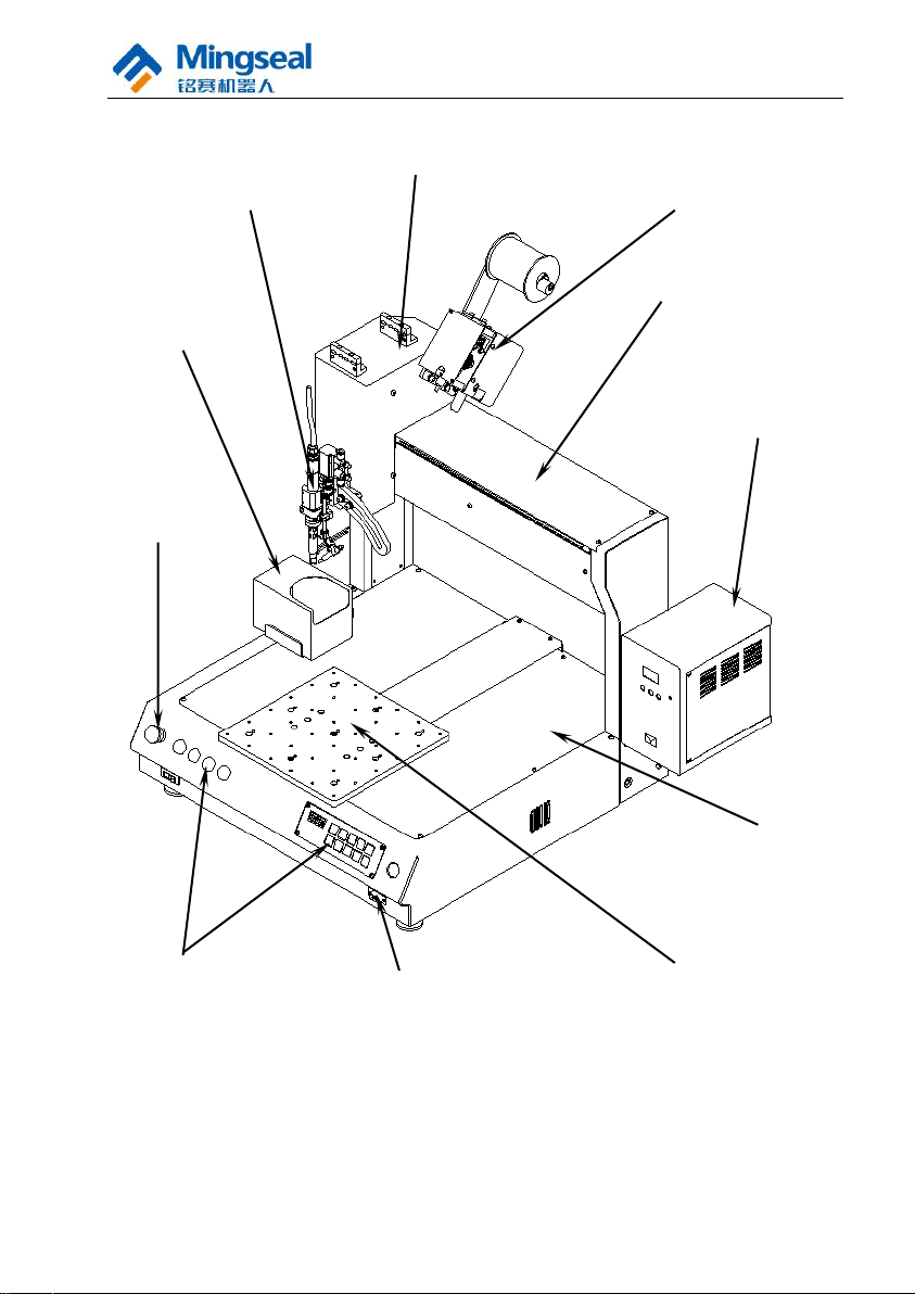
DH-300/400 full automatic soldering robot is a high-quality three-freedom
soldering and welding device developed for welding various workpieces. As
shown in the figure below, with left/right column type mechanical structure, the
soldering robot is suitable for welding the products at the operating point. This
product has the characteristics of very high positioning accuracy, high rigidity
and low center of gravity, and has good movement performance and extremely
low noise. During movement, the machine is stable and is convenient to
download the motion parameters. AUTOCAD data file can be directly read as
the operating data, or the handheld programmer can be used for teaching
programming through RS-232 serial port. Users can develop a variety of tools
as required to be fixed on the carrying plate to meet different requirements of
users. DH-300/400 automatic soldering robot reduces the welding quality
instability caused by manual operation, realizes the automatic operation of
soldering and welding, and ensures the product welding quality.
3
User Manual of DH-300/400 Full Automatic Soldering Robot
Y-axis Mechanism
Welding Head Mechanism
Base
Z-axis Mechanism
X-axis Mechanism
E-stop Button
Programmer Interface
Tin Collecting Box
Tin Feeding Mechanism
Temperature Control Box
Control Button
4

User Manual of DH-300/400 Full Automatic Soldering Robot
1.1 Product Functions and Characteristics
1. X, Y and Z axes can make two-dimensional and three-dimensional
motion;
2. This product is capable of welding at the operating point and drag
soldering;
3. Three-dimensional displacement is controlled by the precision stepping
motor, so that positioning accuracy and repeated positioning accuracy are
high;
4. With CAD Graphics recognition, teaching is simplified and track is more
accurate;
5. This product has compact sealing structure, reasonable layout and higher
cost performance;
6. This product is more convenient to operate and use with the handheld
programmer, and the track storage number is up to 120;
7. Welding time and track running speed can be adjusted by programming;
8. With three-axis fine tuning operation, teaching point coordinates are more
accurate;
9. According to the principles of ergonomics, the worktable height is
optimized to be 135mm, so as to more meet the operation process of
workers and reduce the workers’ feeling of fatigue;
10. According to users’ requirements, specially designed soldering iron
clamps of adjustable height and angle etc. can be equipped;
11. Different tin feeding systems can be equipped according to soldering tin
diameters;
12. Soldering bit temperature, tin feeding speed, tin feeding volume and tin
return volume can be adjusted;
13. The tin feeding wheel and the tin breaking wheel in the tin feeder can be
interchanged.
14. This product has the function of alarm display.
5

User Manual of DH-300/400 Full Automatic Soldering Robot
Axis
DH-300
DH-400
X axis (mm)
335
435
Y axis (mm)
300
400
Z axis (mm)
100
100
1.2 Technical Parameters
DH-300/400 Full Automatic Soldering Robot:
1. Range of motion:
2. Maximum operating speed:
X axis: 800mm/s
Y axis: 800mm/s
Z axis: 400mm/s
3. Wire feeding accuracy: ±0.2mm
4. Range of tin wire: φ0.3~φ1.5mm
5. Repeated accuracy: ±0.02mm
6. Temperature accuracy: ±2º
7. Maximum load:
Worktable: 8Kg (Operating speed < 80mm/s)
Z axis: 2.5Kg (Operating speed < 80mm/s)
8. Overall dimensions: 620mm×600mm×700mm (L, W, H)
9. Weight: 61Kg
10. Task storage number: 120
Parameter Requirements of Welding System
1. Temperature range of soldering bit: 200.0-480.0ºC
2. Tin feeding speed: 0-50mm/s
3. Tin return volume: 0.1-5.0mm
4. Tin blowing time: 0.0-9.9s
5. Manual tin feeding function
6. Manual tin return function
7. Manual tin blowing function
8. Applicable tin wire diameter: 0.3mm, 0.4mm, 0.5mm, 0.6mm,
0.8mm, 1.0mm, 1.2mm, 1.5mm
9. Soldering bit: High-frequency vortex soldering bit
10. Welding status ready function
6

User Manual of DH-300/400 Full Automatic Soldering Robot
1.3 Operating Environment
1. Application range of supply voltage: 220V AC, fluctuation range
+10%~-15%, frequency 50±1 Hz
2. Ambient temperature: 0 ~ 40ºC
3. Relative humidity: 20% ~ 90% (no condensation)
4. Pressure requirement of air source: 0.3MPa ~ 0.6MPa
7
User Manual of DH-300/400 Full Automatic Soldering Robot
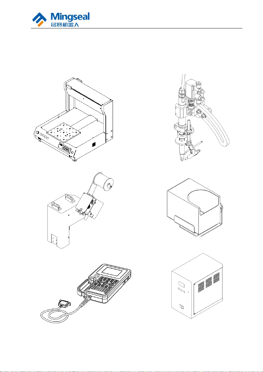
Z Axis Assembly
Soldering Bit Assembly
Body
Tin Blowing Box
Programmer
Temperature
Control Box
2. Equipment Installation and Commissioning
2.1 Unpacking
Please confirm whether there are the following items after unpacking.
8
User Manual of DH-300/400 Full Automatic Soldering Robot
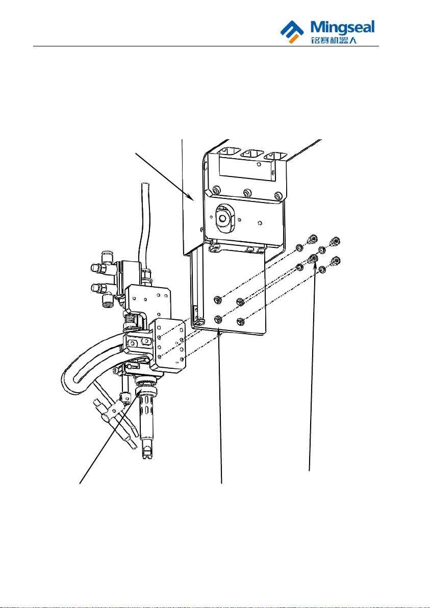
Screw M4x12
Spring Washer 4
Soldering Iron Part
Z Axis Part
Z-axis Movable Block
2.2 Assembling
2.2.1 Installation of Soldering Bit Assembly
The soldering bit assembly of the three-axis welding machine is installed
on the Z-direction movable block of Z axis.
9
User Manual of DH-300/400 Full Automatic Soldering Robot
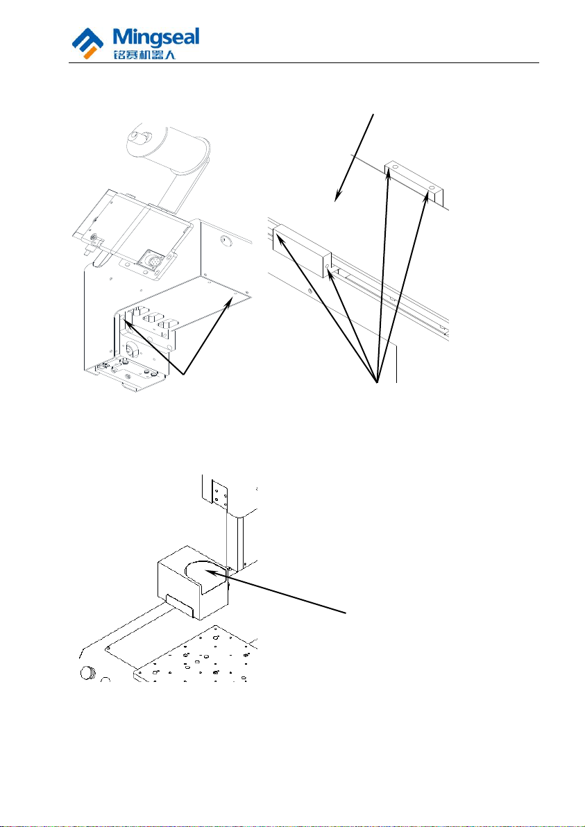
M4x16 hexagon socket
screw and spring washer
Z Axis Part
X Axis
Connecting screw holes
on both sides
Approximate position of tin
collecting box after
assembling; this position is
adjustable
2.2.2 Installation of Z Axis
2.2.3 Installation of Tin Collecting Box
There are two screw holes on the upper plane of Y-axis outer cover; fix the tin
collecting box on the two screw holes of Y-axis outer cover with two M3X8
hexagon socket screws and washers with corresponding specification.
10
User Manual of DH-300/400 Full Automatic Soldering Robot
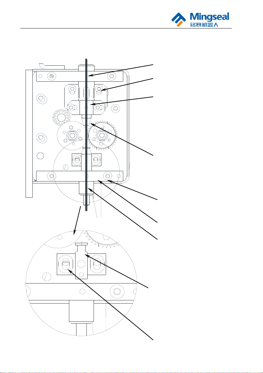
The wire inlet of tin guiding pipe shall be
close to the tin feeding wheel as far as
possible here so as to help to reduce the wire
blocking phenomenon.
Note: To feed the tin, the wire feeding guide
sleeve seat shall be adjusted to the rightmost
side, and the adjusting base shall be adjusted
to the downmost side. To break the tin, the
wire feeding guide sleeve seat shall be
adjusted to the leftmost side, and the
adjusting base shall be adjusted to the
uppermost side.
Tin Blocking Detecting Piece
The tin blocking detecting piece shall be
close to the tin feeding wheel as far as
possible, and the vertical position can be
adjusted through the adjusting seat of
adjusting piece.
Special Note: The tin blocking copper
detecting ring shall not be in contact
with the tin feeding wheel and other
metals so as to avoid failure due to
forming a loop with the tin feeder.
Fixed Seat of Tin Guiding Pipe
Tin Guiding Pipe
Note: This is where the shoulder and the
bottom of the fixed seat of tin guiding
pipe shall fit together as far as possible.
Thick black line indicates the passing
path of tin wire
Adjusting Base
Wire Feeding Guide Sleeve Seat
2.2.4 Installation of Tin Guiding Pipe
Select the corresponding tin feeding hose according to the required diameter
series of tin wire.
Adjusting Seat of Adjusting Piece
11
User Manual of DH-300/400 Full Automatic Soldering Robot
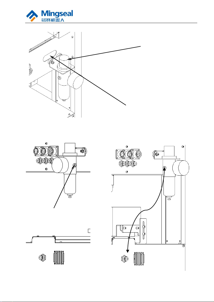
Connection of 6mm air pipe
Connection of air source
点焊机背面
点焊机背面
Oil-water Separator
Absorption Groove of
Oil-water Separator
2.2.5 Installation of Oil-water Separator
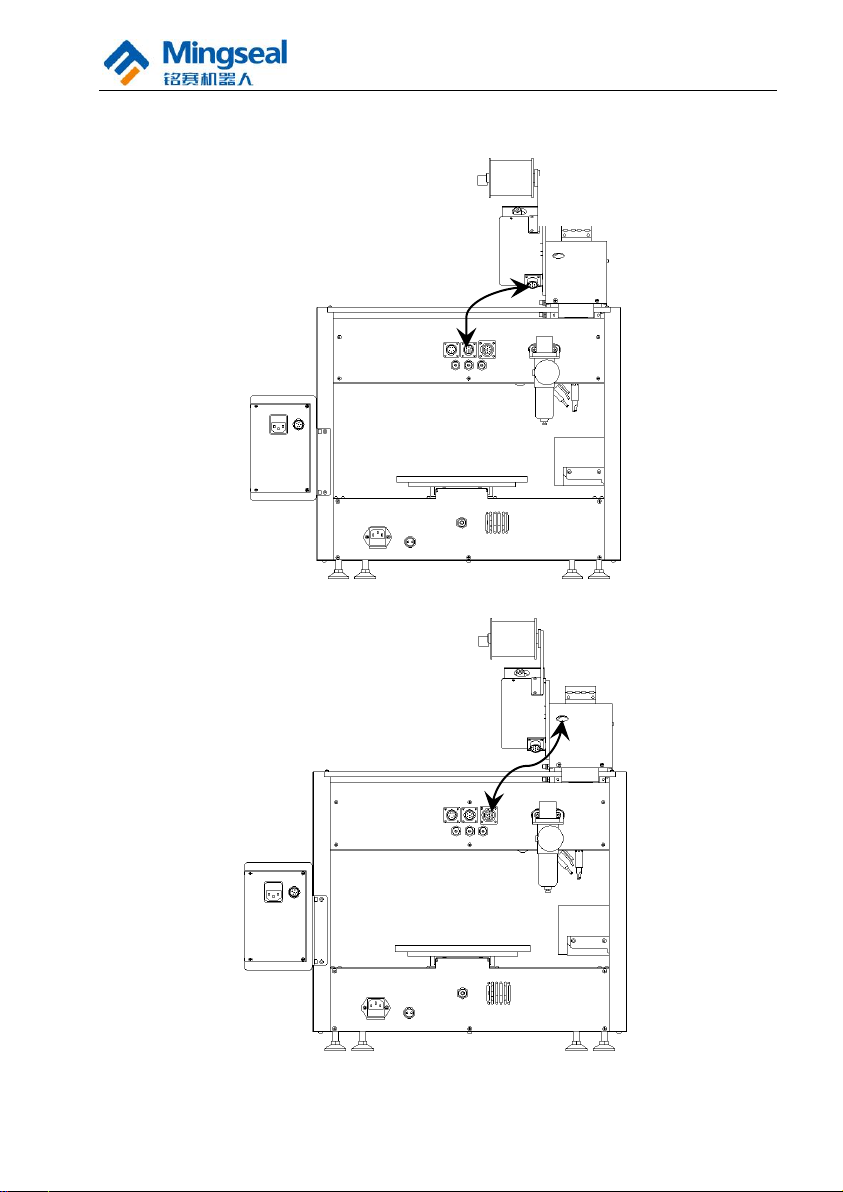
2.2.6 Connection of Air Pipe
(1) Connection of air pipe for oil-water separator
12
User Manual of DH-300/400 Full Automatic Soldering Robot
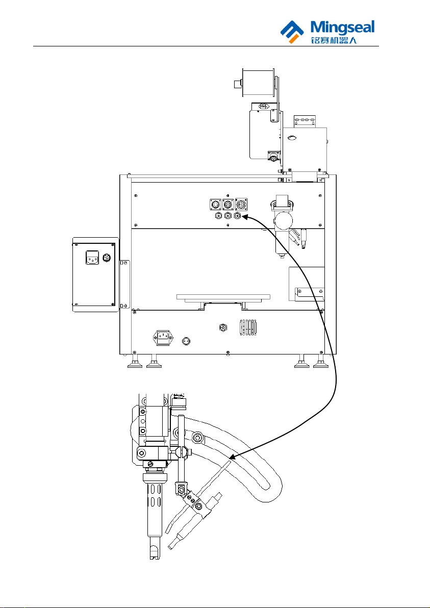
Back of spot welding machine
(2) Connection of air pipe for tin blowing
13
User Manual of DH-300/400 Full Automatic Soldering Robot
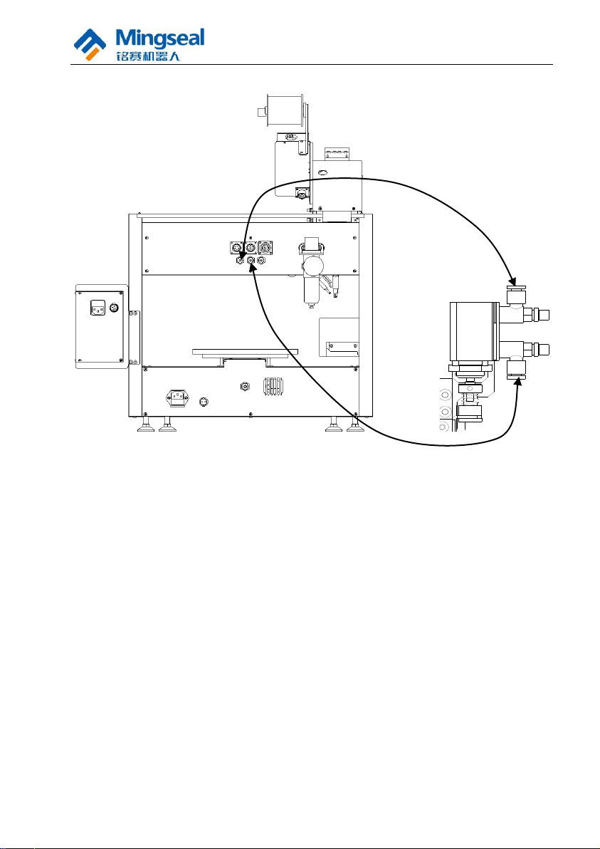
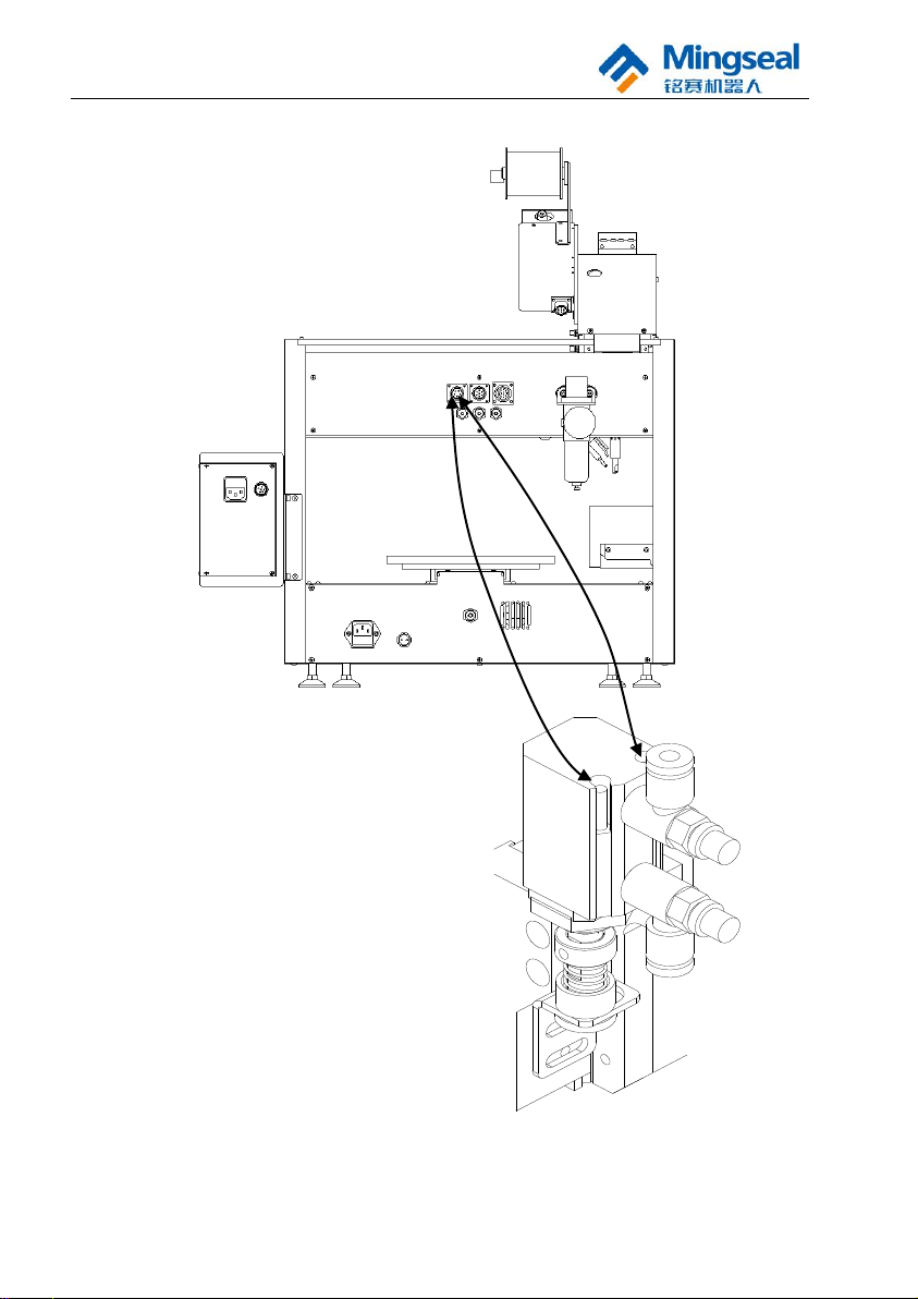
(3) Connection of air pipe for cylinder
14
User Manual of DH-300/400 Full Automatic Soldering Robot
2.2.7 Connection of Electric Wire
(1) Connection of electric wire for welding head (6-pin aviation plug)
15
User Manual of DH-300/400 Full Automatic Soldering Robot
(2) Connection of electric wire for wire feeding (7-pin aviation plug)
(3) Connection of electric wire for Z axis (12-pin aviation plug)
16
User Manual of DH-300/400 Full Automatic Soldering Robot
Divide the electric wire into two
strands to be respectively connected
to the connecting terminals of the
cylinder.
(4) Connection of electric wire for miniature cylinder (5-pin aviation plug)
17
User Manual of DH-300/400 Full Automatic Soldering Robot
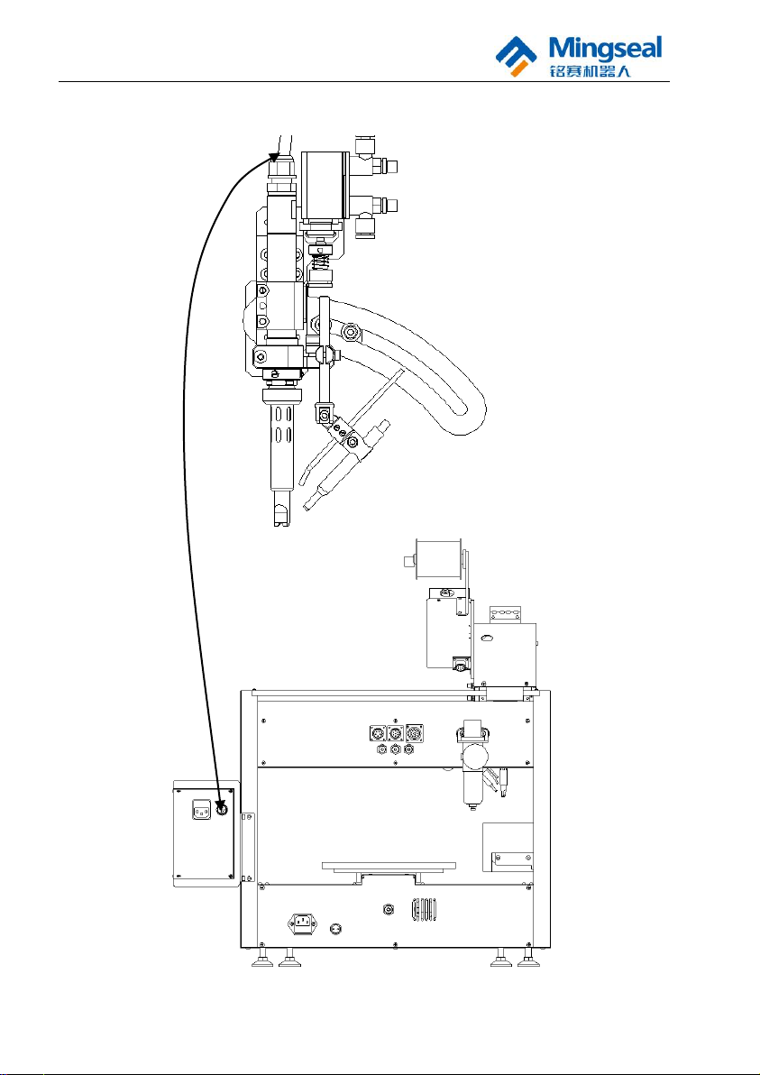
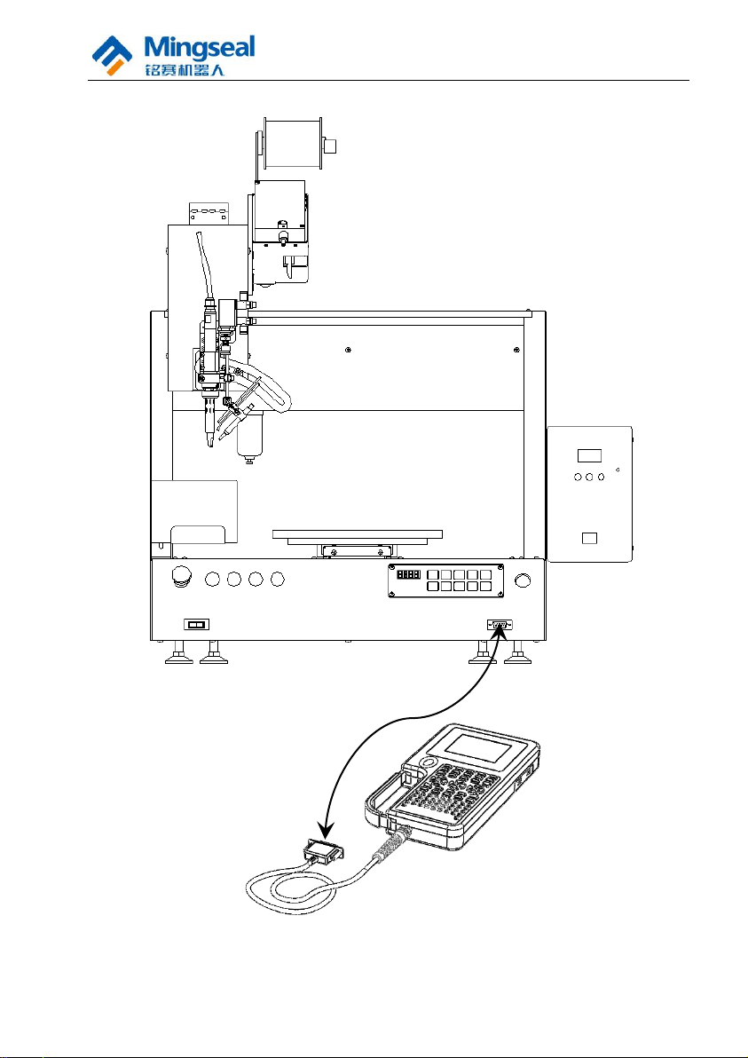
(5) Connection of programmer interface
18
User Manual of DH-300/400 Full Automatic Soldering Robot
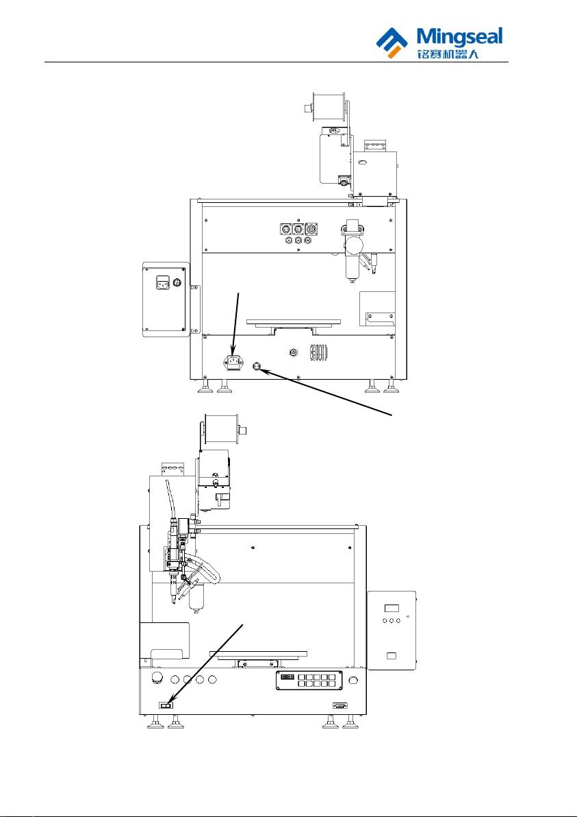
Foot Switch
Power Interface
Power Switch
(6) Power supply connection and switch
19
User Manual of DH-300/400 Full Automatic Soldering Robot
Handle
Clearance
Adjusting Knob
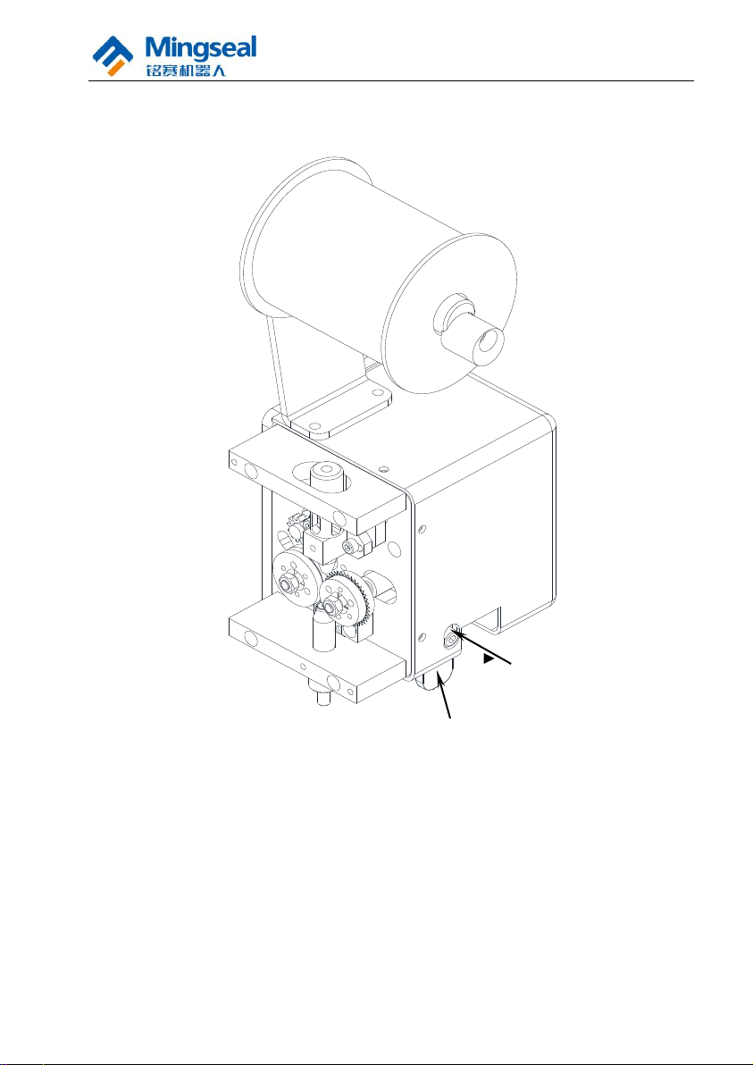
2.3 Installation and Adjustment of Tin Wire
When installing the tin wire, select the tin wire with required diameter series.
Thread the tin wire through the guide sleeve opening at the top of the tin feeder,
lift the handle to let the tin wire pass through the clearance of friction wheel
and reach the interior of the wire leading opening at the bottom, and then close
the handle to carry out the tin feeding operation, and observe the clearance of
friction wheel. Adjust the clearance with M4 hexagon socket screw driver.
20

User Manual of DH-300/400 Full Automatic Soldering Robot
2.3.1 Clearance Adjustment Methods
(1) Clearance adjustment methods in case of tin feeding:
① When the tin wire of 0.3mm is used, rotate the adjusting screw
counterclockwise until the clearance of tin feeding wheel is minimum.
When you feel the adjusting screw is very loose and the force is not
required during rotation, the minimum clearance is reached. At this time,
rotate the adjusting screw clockwise. When you feel the required force is
increased, rotate the adjusting screw by 1/2 turn to 2/3 turn.
② When the tin wire of 0.4mm is used, the adjustment method is the same as
that of the tin wire of 0.3mm.
③ When the tin wire of 0.5mm, 0.6mm, 0.8mm, 1.0mm or 1.2mm is used, it
is only necessary to adjust the clearance of tin feeding wheel to the
minimum clearance.
④ When the tin wire of 1.4mm or 1.5mm is used, the adjustment method is
the same as that of the tin wire of 0.3mm.
(2) Clearance adjustment methods in case of tin breaking:
① When the tin wire of 0.6mm, 0.8mm, 1.0mm or 1.2mm is used, it is only
necessary to adjust the clearance of tin feeding wheel to the minimum
clearance.
② When the tin wire of 1.4mm or 1.5mm is used, the adjustment method is
the same as that of the tin wire of 0.3mm.
2.3.2 Service Life of Tin Breaking Blade
1. Force bearing mode of blade
The maximum penetrating depth of the blade is 0.75mm (The maximum
diameter of tin wire is 1.5mm), and the whole depth of the blade is 2.7mm. As
shown in the figure below, the main force bearing part is the tooth tip, which is
a part easy to wear on the blade and is a main factor influencing the service life.
21
 Loading...