

Page 1
Wireless Access Point
Quick Start Guide
Revision B
WAP3_QSG_EN_B
Page 2

Page 3

Contents
Contact Information..........................................................................................................5
Chapter 1: Introduction..............................................................7
1.1 What's In The Box.............................................................................................8
1.2 WAP3 At A Glance...........................................................................................9
1.3 Cabling Requirements.....................................................................................10
Chapter 2: Web Conguration.................................................13
2.1 Device Discovery............................................................................................13
2.2 Logging onto the Web Browser Interface.......................................................14
2.3 Conguration screen.......................................................................................15
Chapter 3: Centralised Conguration Management .............17
Chapter 4: Antenna Conguration..........................................19
Chapter 5: Restoring Factory Default Settings.......................21
Chapter 6: Repairs and Maintenance......................................23
WAP3 Quick Start Guide3Revision B
Page 4

Revision B4WAP3 Quick Start Guide
Page 5

Contact Information
AUSTRALIA - Sydney
113 Wicks Road
North Ryde NSW 2113 AUSTRALIA
Tel: +61 2 9491 6500
CANADA - Sudbury
1085 Kelly Lake Road
Sudbury Ontario P3E 5P5 CANADA
Tel: +1 705-675 7468
CHINA - Hangzhou
4F, Building 1
1413 Moganshan Road
Hangzhou CHINA 310011
Tel: +86 571 85803320x206
UNITED STATES - Denver
13301 W 43rd Drive
Golden Colorado 80403 USA
Tel: +1 303-951 0570
GERMANY - Berlin
Mine Site Technologies (GmbH)
Uhlandstr. 20-25
10623 Berlin
GERMANY
Tel: +49 30 8861 4511
WAP3 Quick Start Guide5Revision B
Page 6

Page 7

Chapter
1
Introduction
Mine Site Technologies' ImPact WAP3 is an 802.11 b/g wireless access point. It is used
in conjunction with the ImPact Wireless Network Switch to provide a wireless network
for underground mining environments. The WAP3 forms part of the ImPact network
infrastructure, in which voice, tracking, video, automation and process control applications
can be used to enhance mining safety and productivity.
The WAP3 has the following features:
• 10/100 Ethernet port
• 802.11b/g wireless radio
• Rugged enclosure meeting IP66 standards
•
AeroScout®Tag reading capability, allowing real time tracking of assets and personnel
• Low power consumption, wide input voltage range (10-50VDC)
• Simple Network Management Protocol (SNMP) support for remote monitoring
• Trivial File Transfer Protocol (TFTP) based central conguration management
• Wireless Distribution System (WDS) for wireless trunking with other ImPact network
devices.
WAP3 Quick Start Guide7Revision B
Page 8
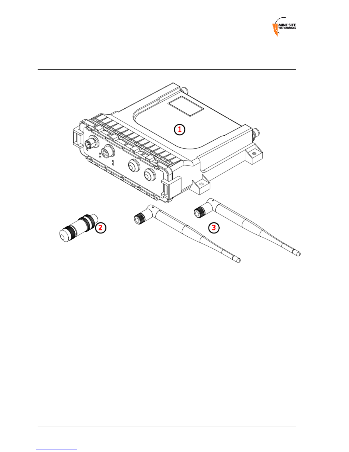
1.1 What's In The Box
1.
WAP3 unit x1
2.
M12 Ethernet connector x1
3.
RP-TNC WHIP Antenna x2
4.
Quick Start Guide
Revision B8WAP3 Quick Start Guide
Introduction
Page 9

1.2 WAP3 At A Glance
1.
MAIN RP-TNC Connector
2.
AUX RP-TNC Connector
3.
Serial Number and MAC address
4.
Console Port
5.
Ethernet Port
6.
Power LED - Solid red indicates the unit has power.
7.
Status LED - Flashing red indicates normal operation.
8.
LAN LED - Lit when the Ethernet link is established, ashes when data is transmitted
or received.
9.
WLAN LED - Lit when the WLAN is active, ashes when wireless data is transmitted
or received.
10.
Data LED - Flashes when a Wi-Fi tag is detected.
11.
AUX LED - This LED has no function on the WAP.
12.
Default Button - Press this in conjunction with the Reset Button return the device to
factory default settings (see Restoring Factory Default Settings on page 21).
13.
Reset Button - Pressing this will cause the device to reboot.
WAP3 Quick Start Guide9Revision B
Introduction
Page 10

1.3 Cabling Requirements
The WAP3 is typically powered from an 802.3af (Mode A) Power over Ethernet (PoE)
supply, which sends power down the Ethernet cable. The WAP3 is normally connected
and powered via an M12-to-RJ45 Ethernet cable from the WAP3's Ethernet port to an
MST Wireless Network Switch (WNS, NS50), but can also be powered by a separate
PoE power supply.
Wireless connectivity is provided via the Main and/or Aux RP-TNC ports on the back
of the unit. Antennas can be connected to the ports directly or with coaxial cables. Coaxial
cable length should be kept as short as possible to minimise signal loss. It is recommended
to keep cable length to less than 10 metres.
M12 Ethernet Connection
Revision B10WAP3 Quick Start Guide
Introduction
Page 11

M12 Console Connection
If PoE is not available, the device can be powered directly via the console connector as
shown below.
Important:
• All coaxial cable and antenna connections must be electrically insulated using
self-amalgamating rubber tape.
• The PoE supply must conform to the 802.3af (Mode A) standard. The WAP3 is
NOT compatible with Mode B power supplies.
WAP3 Quick Start Guide11Revision B
Introduction
Page 12

Page 13

Chapter
2
Web Configuration
The WAP3 has a built-in web-server that can be accessed from a PC to congure the
device's settings. The IP address of the WAP3 can be discovered and congured using
the MST Device Scanner software tool.
Note: The Device Scanner tool can be downloaded from
http://minesite.net/downloads.
2.1 Device Discovery
The MST Device Scanner can be used to discover and change the IP address of ImPact
devices from any PC connected to the same network switch (i.e. the tool will not work if
there is a router between the PC and the device being scanned). Upon opening, the Device
Scanner will automatically scan for devices.
To use the Device Scanner, navigate to the folder where the program is stored, and double
click devicescanner.exe.
The Device Scanner shows several columns of information for each discovered device:
• Name - The hostname of the device. For the WAP, the default name is MST PoE
Access Point.
• IP Address - This can be set remotely on the device, in Settings > LAN > LAN
Settings , or from the Device Scanner (see below).
WAP3 Quick Start Guide13Revision B
Page 14

• Type - The device type or model.
• MAC Address - The MAC address of the device.
• Interface - The network interface via which the Device Scanner is communicating
with the device.
• ID - The serial number on the device housing.
• Firmware - The version number of the rmware running in the device.
• Status - The uptime of the device. This can be used to easily determine which devices
have recently been connected to the network.
• Revision - The hardware revision of the main processor PCB (not the overall product
version).
To discover devices after the program has been opened, click the Scan button. To allow
the Device Scanner to continually check for new devices, tick the Continuous checkbox.
To change the IP address or settings of a device, highlight the row, then click the
Congure IP button. This will open a dialogue box allowing you to set the device to
Obtain an IP address automatically using DHCP, or to manually set an IP address,
Subnet Mask and Default Gateway with the Use the following IP address option.
2.2 Logging onto the Web Browser Interface
Once the device's address is known, a web browser can be used to congure the remainder
of the device's settings. The web browser interface has a login screen with access at two
levels:
• ADMIN — Allows settings to be viewed and modied. Default password is ‘admin’.
• USER — Allows settings to be viewed but not modied. By default there is no
password.
Revision B14WAP3 Quick Start Guide
Web Conguration
Page 15

Note: Each Wireless Access Point is tted with a single Wireless Access Card
(WAC). Some documentation may use the term 'WAC' to refer to the wireless radio
inside the WAP.
To log in to the web browser interface:
1.
Launch your web browser and enter http://<WAP IP address> in the address eld.
2.
Press the ENTER key. The login screen is displayed.
3.
In the LOGIN dialog box, select Admin from the User Name drop-down box, and
type the password in the Password eld. The factory default password is admin.
4.
Click Log In. The conguration home screen is displayed.
2.3 Configuration screen
Once logged in, the conguration screen will be available.
The conguration options are divided among three section tabs across the top, with the
following pages:
WAP3 Quick Start Guide15Revision B
Web Conguration
Page 16

• STATUS - Displays the running state of the device.
• Device Info - System time, rmware version, LAN and wireless LAN summary
information.
• Wireless - Information about wireless clients connected to the access point.
• Logs - Device logs, ltered by the type of logged events and the event level.
• Statistics - Network trafc statistics for the WAP3's LAN interface and each of the
wireless SSIDs.
• Tracking - Status of tracking servers registered to the WAP3.
• Tags - The last ten AeroScout tag reads when asset tracking and location services
are enabled.
• TOOLS
• Admin - Administrator/User login and passwords, and device conguration
backup/restore settings.
• Time - Regional time settings and NTP server options.
• System - device reboot and factory default options.
• Firmware - Current rmware information and rmware upgrade options.
• SETTINGS
• Cong Management - TFTP settings for older ICAs (v1.3.1 or earlier) and 3rd
party TFTP servers.
• SNMP - Settings for SNMP pollers to query the device.
• LAN - Network settings for the WAP3.
• Wireless
• Radio - Wi-Fi settings and channels.
• Networks - WLAN conguration.
• EAP - RADIUS server authentication settings for WPA Enterprise networks.
• WDS Settings - Wireless Distribution System settings for connecting ImPact
network devices where bre or Ethernet is not practical.
• Tracking - AeroScout/MST Tracker Engine settings.
• MAC Address Filter - MAC addresses to be allowed or denied access to the
network.
• VLAN List - Denes VLANs and the priority that will be assigned to trafc on
each.
• VLAN Port Map - Enables a VLAN to be assigned to a specic wireless network
(SSID).
For more information on any of these menus, see the WAP3 Wireless Access Point User
Guide.
Revision B16WAP3 Quick Start Guide
Web Conguration
Page 17

Chapter
3
Centralised Configuration Management
For large networks of underground devices, individual conguration via the web interface
for each device is time-consuming and prone to human error. In order to manage large
networks, centralised conguration management is strongly recommended. It uses Trivial
File Transfer Protocol (TFTP) to enable devices to read and apply conguration les
from a TFTP server.
There are two ways to take advantage of TFTP-based centralised conguration
management:
ICA v1.4.0 or later - Device Management via the ICA Administration Console
(RECOMMENDED)
For networks with an ICA v1.4.0 or higher, AP settings can be managed from the ICA
Administration console. A customisable Site Default template is included at installation,
and further templates can be copied from it and modied separately. Additionally,
individual APs can have specic settings overridden via the Administration Console.
In this case, the ICA will push conguration changes to the APs with no need to log onto
the devices' web interface.
ICA v1.3.1 or earlier, and 3rd party TFTP servers - Manually editing
configuration files
For older ICA systems and other TFTP servers, text-based conguration les must be
edited and uploaded to the ICA manually, and APs must be congured to periodically
self-check and fetch new conguration les from the server when available.
Note: For more information and procedures for setting up conguration management,
see the WAP3 Wireless Access Point User Guide.
WAP3 Quick Start Guide17Revision B
Page 18

Page 19

Chapter
4
Antenna Configuration
The WAP3 can operate with a single antenna or diversity antennas. Diversity antennas
provide improved signal reception.
Single Antenna
• Connect the antenna to the MAIN antenna port on the back of the unit.
• In the web interface, go to Settings > Radio > Radio Settings , and set both Transmit
Antenna and Receive Antenna to Main.
Diversity Antennas
Connect antennas to the MAIN and AUX ports.
In the web interface, go to Settings > Radio > Radio Settings , and set Transmit
Antenna to Main, and Receive Antenna to Diversity.
Important:
• Ensure that the physical connection of antennas is consistent with the Transmit
and Receive Antenna conguration settings.
• When operating with Diversity antennas, both antennas should be oriented to
point in the same direction.
WAP3 Quick Start Guide19Revision B
Page 20

Page 21

Chapter
5
Restoring Factory Default Settings
An operator can return the unit to factory defaults with the following steps:
1.
Hold down the DEFAULT button on the front of the unit.
2.
Press and release the red RESET button on the front of the unit while keeping the
DEFAULT button depressed.
3.
Continue to hold the DEFAULT button for 5 seconds after the unit restarts.
4.
Release the DEFAULT button to continue the boot process with the newly defaulted
conguration.
WAP3 Quick Start Guide21Revision B
Page 22

Page 23

Chapter
6
Repairs and Maintenance
It is recommended that all WAPs, antennas, cables and connectors are inspected at regular
intervals to ensure safe and reliable operation. A maintenance checklist is provided below.
ActionInspection
Inspect the outer case for any structural damage.Structural
Check there is no excessive damage or markings to the case.
Check coaxial cable connections are securely fastened to the WAP unit.Coaxial cables
Check the coaxial cable for any damage.
Check the antennas for any damage.Antennas
Check the antennas' connections to the coaxial cable for any damage to the
insulation or connection.
Check the antennas' directional alignment.
Check that the device conguration (for single or diversity antennas)
corresponds to the physical antennas attached to the device.
Check all Ethernet cable connections are secure.Ethernet connections
Check dust covers are present and secure on unused Ethernet ports.
Check the power LED is solid red.Display LEDs
Check the status LED is blinking red (at approximately a 1 second interval).
Testing RF transmit
path for WAP
1.
Stand 50M away from the ImPact WAP.
2.
Using a MinePhone handset, verify the signal strength is within
specication. (Refer to site specic commissioning data).
Testing RF receive
path for WAP
1.
Stand 50M away from the ImPact WAP with two AeroScout tags.
2.
Open the web browser interface and select the STATUS > TAGS web
page.
3.
Verify that the two tags have been detected, and verify that the received
signal strength is within specication (Refer to site specic
commissioning data).
Note: A tracker server must be congured in order for the tags to be
displayed on the web interface.
WAP3 Quick Start Guide23Revision B
Page 24

Note: Please contact MST for all maintenance and repair enquiries.
Revision B24WAP3 Quick Start Guide
Repairs and Maintenance
 Loading...