

Page 1

Wireless Network Switch
User Manual
Page 2

Page 3

Contents
Revision History............................................................................................................................................7
Contact Information.......................................................................................................................................9
About This Manual......................................................................................................................................11
Chapter 1: Understanding the Wireless Network Switch....................13
Chapter 2: Network System Design ........................................................19
1.1 Hardware Overview...................................................................................................................14
1.2 System Layout ..........................................................................................................................16
1.3 Connectivity...............................................................................................................................16
1.3.1 Composite Fibre Ports ...............................................................................................17
1.3.2 Ethernet Ports.............................................................................................................17
1.3.3 Wireless Access..........................................................................................................18
2.1 Installation Types and Coverage................................................................................................20
2.2 Power Requirements..................................................................................................................20
2.3 Choosing Antennas ...................................................................................................................20
2.4 Placement of Wireless Network Switches.................................................................................21
2.5 Placement of Antennas..............................................................................................................21
2.6 Determining Wi-Fi Distances between Wireless Network Switches.........................................23
2.6.1 Line of Sight Distances...............................................................................................23
2.6.2 Distances Around Curves...........................................................................................23
Chapter 3: Installation..............................................................................25
3.1 WNS Mounting Options............................................................................................................26
3.2 Antenna Mounting Options.......................................................................................................27
3.3 Installation Schemes..................................................................................................................28
3.3.1 Installation in a Straight Drive....................................................................................28
3.3.2 Installation in a Curved Decline / Incline...................................................................29
3.3.3 Installation in a Stope.................................................................................................30
3.3.4 Installation at an Intersection .....................................................................................31
3.4 Connecting Power to the Wireless Network Switch..................................................................33
3.4.1 Installing Additional Power........................................................................................34
3.5 Handling Composite Cable During Installation........................................................................34
3.6 Connecting Composite Cable to the Wireless Network Switch................................................35
3.7 Connecting Ethernet Cable to the Wireless Network Switch....................................................36
3.8 Connecting Antennas to the Wireless Network Switch ............................................................38
3.9 Manual Reset and Reboot .........................................................................................................40
Chapter 4: Understanding VLANs .........................................................43
Wireless Network Switch User Manual3Revision A
Page 4

4.1 Understanding Trunk and Access Ports.....................................................................................44
4.1.1 Trunk Ports.................................................................................................................44
4.1.2 Access Ports................................................................................................................44
4.1.3 Port Allocation............................................................................................................45
4.2 VLANs and Wireless Networks.................................................................................................45
4.3 Native VLAN ............................................................................................................................46
Chapter 5: Configuration Using the Web Interface ..............................49
5.1 Logging onto the Web Browser Interface..................................................................................50
5.2 Configuration screen..................................................................................................................50
5.3 Basic Tab....................................................................................................................................51
5.3.1 Setting Up the LAN....................................................................................................51
5.3.2 Configuring Wireless Radio.......................................................................................52
5.3.3 Configuring Wireless Networks.................................................................................53
5.3.4 Configuring Wireless Extensible Authentication Protocol (EAP)..............................56
5.3.5 Configuring Asset Tracking and Location Based Services........................................57
5.3.6 Configuring Ethernet Switch Ports.............................................................................59
5.4 Advanced Tab............................................................................................................................60
5.4.1 Enabling the MAC Address Filter..............................................................................60
5.4.2 Fine Tuning Wireless Performance.............................................................................62
5.4.3 Defining VLANs.........................................................................................................63
5.4.4 Configuring the VLAN Port Map...............................................................................65
5.4.5 Wireless Distribution System (WDS) settings............................................................66
5.5 Tools Tab....................................................................................................................................67
5.5.1 Configuring Administrator and User Settings............................................................68
5.5.2 Saving and Restoring Configuration Settings.............................................................69
5.5.3 Activating Power Over Ethernet.................................................................................70
5.5.4 Setting the Time..........................................................................................................71
5.5.5 Rebooting or Restoring the Network Device..............................................................73
5.5.6 Upgrading Firmware...................................................................................................74
5.6 Status Tab...................................................................................................................................76
5.6.1 Obtaining Device Information....................................................................................76
5.6.2 Wireless Client Information........................................................................................77
5.6.3 Viewing System Logs.................................................................................................78
5.6.4 Viewing Network Traffic Statistics.............................................................................80
5.6.5 Viewing Ethernet Switch Information........................................................................81
5.6.6 Viewing Tracking Information....................................................................................82
5.6.7 Viewing Recent Tag Reports.......................................................................................82
Chapter 6: Centralised Configuration Management ............................85
6.1 Overview....................................................................................................................................86
6.2 Site Configuration files..............................................................................................................86
6.3 Editing Site Configuration Files................................................................................................87
6.3.1 Network......................................................................................................................87
6.3.2 System .......................................................................................................................88
Revision A4Wireless Network Switch User Manual
Page 5

6.3.3 Setting the Time .........................................................................................................88
6.3.4 Enabling Power Over Ethernet ..................................................................................89
6.3.5 Setting up Asset Tracking and Location Servers........................................................89
6.3.6 Switch Configuration .................................................................................................90
6.3.7 VLAN Configuration..................................................................................................91
6.3.8 Wireless EAP Configuration.......................................................................................93
6.3.9 Wireless Network Configuration................................................................................93
6.4 Device Configuration Files........................................................................................................96
6.5 Editing Device Configuration Files...........................................................................................96
6.6 Applying Configuration Files ...................................................................................................97
Appendix A: Troubleshooting Guide ....................................................101
Appendix B: Composite Cable Testing..................................................103
B.1 Visual Inspection of the Fibre Optic Cable.............................................................................103
B.2 Measuring and Testing for Power Loss...................................................................................103
Appendix C: Ethernet Cable Specifications.........................................105
Appendix D: Connecting a PC to an ImPact Network Device............107
Appendix E: Discovering Devices on the Network...............................109
Appendix F: Timezone Indices and Offsets .........................................111
Appendix G: Power Consumption Guide.............................................115
Appendix H: Maintenance Check-list...................................................117
Appendix I: ImPact Wireless Network Switch Specifications.............119
Appendix J: Acronyms...........................................................................121
Appendix K: Hardwar e W arranty and Softwar e License Agreement.123
K.1 Hardware Warranty.................................................................................................................123
K.2 Software End User License Agreement..................................................................................123
Wireless Network Switch User Manual5Revision A
Page 6

Revision A6Wireless Network Switch User Manual
Page 7

Revision History
DateChangeRevision
July 2011Manual for WNS hardware Re v D and firmware 2.22.0A
Copyright © 2011 Mine Site Technologies Pty Ltd. All rights reserved. Mine Site Technologies Pty Ltd
reserves the right to make changes to specifications and information in this manual without prior notice.
Mine Site Technologies Pty Ltd accepts no responsibility for any errors or omissions contained in this
manual.
Wireless Network Switch User Manual7Revision A
Page 8

Page 9

Contact Information
AUSTRALIA
Sydney
25-27 Whiting Street
Artarmon NSW 2064 AUSTRALIA
Tel: +61 2 9437 4399
CANADA
Sudbury
1085 Kelly Lake Road
Sudbury Ontario P3E 5P5 CANADA
Tel: +1 705-675 7468
CHINA
Hangzhou
4th Floor, Building 1
No. 5 Xianghong Road
Hangzhou CHINA 310011
Tel: +86 571 85803320x206
UNITED STATES
Denver
13301 W 43rd Drive
Golden Colorado 80403 USA
Tel: +1 303-951 0570
Wireless Network Switch User Manual9Revision A
Page 10

Page 11
About This Manual
This manual describes features and functions of the WNS (W ireless Network Switch) hardware. It provides
information about system design, hardware installation, configuration and how to troubleshoot any issues.
You will find it easier to use the manual if you are familiar with networking systems and have an
understanding of electronics in a network environment.
Conventions used in the manual
This publication uses the following conventions to highlight and convey information:
• Text that requires input from an operator is boldfaced.
• Operator interface screen control names are boldfaced.
• Keyboard input keys are CAPITALISED.
Icons
Icons are used in the manual to highlight specific information as shown the table below.
DescriptionIcon
Note:
Important:
Caution:
Additional Support
For additional support please visit our website www.minesite.com.au.
The Note icon indicates important information or references to the
user.
The Important icon contains information to prevent damage to the
product and injury to the user.
The Caution icon indicates to stop and pay attention or an action not
to be performed.
Wireless Network Switch User Manual11Revision A
Page 12

Page 13

Chapter
1
Understanding the Wireless Network Switch
Topics:
• Hardware Overview
• System Layout
• Connectivity
This chapter presents the features and functions of the ImPact W ireless
Network Switch (WNS) and shows how it is integrated within a
network.
Mine Site Technologies' ImPact WNS consists of a managed fibre
optic Ethernet switch and two 802.11 b/g wireless access points. It
provides wired and wireless network access for surface and hard rock
mining environments. The WNS forms a network infrastructure where
voice, tracking, video and process control applications can be used to
enhance mining safety and communications.
The WNS has the following features:
• Four fibre optic Gigabit Ethernet ports
• Four internal 10/100 Ethernet ports
• Four external 10/100 Ethernet ports with Power o ver Ethernet (PoE)
capability
• Two 802.11b/g wireless access points
• Powder-coated stainless steel enclosure meeting Ingress Protection
IP66 standards
• AeroScout® tag reading capability, allowing real time tracking of
assets and personnel
• Composite cabling system incorporating fibre optic data and DC
power
• Low power design, with a wide input voltage from 10-50VDC
• Simple Network Management Protocol (SNMP) support for remote
monitoring
• Wireless Distribution System (WDS) for wireless VLAN trunking
with other ImPact network devices.
For detailed specifications on the WNS, see ImPact Wireless Network
Switch Specifications on page 119.
Wireless Network Switch User Manual13Revision A
Page 14
Understanding the Wireless Network Switch
1.1 Hardware Overview
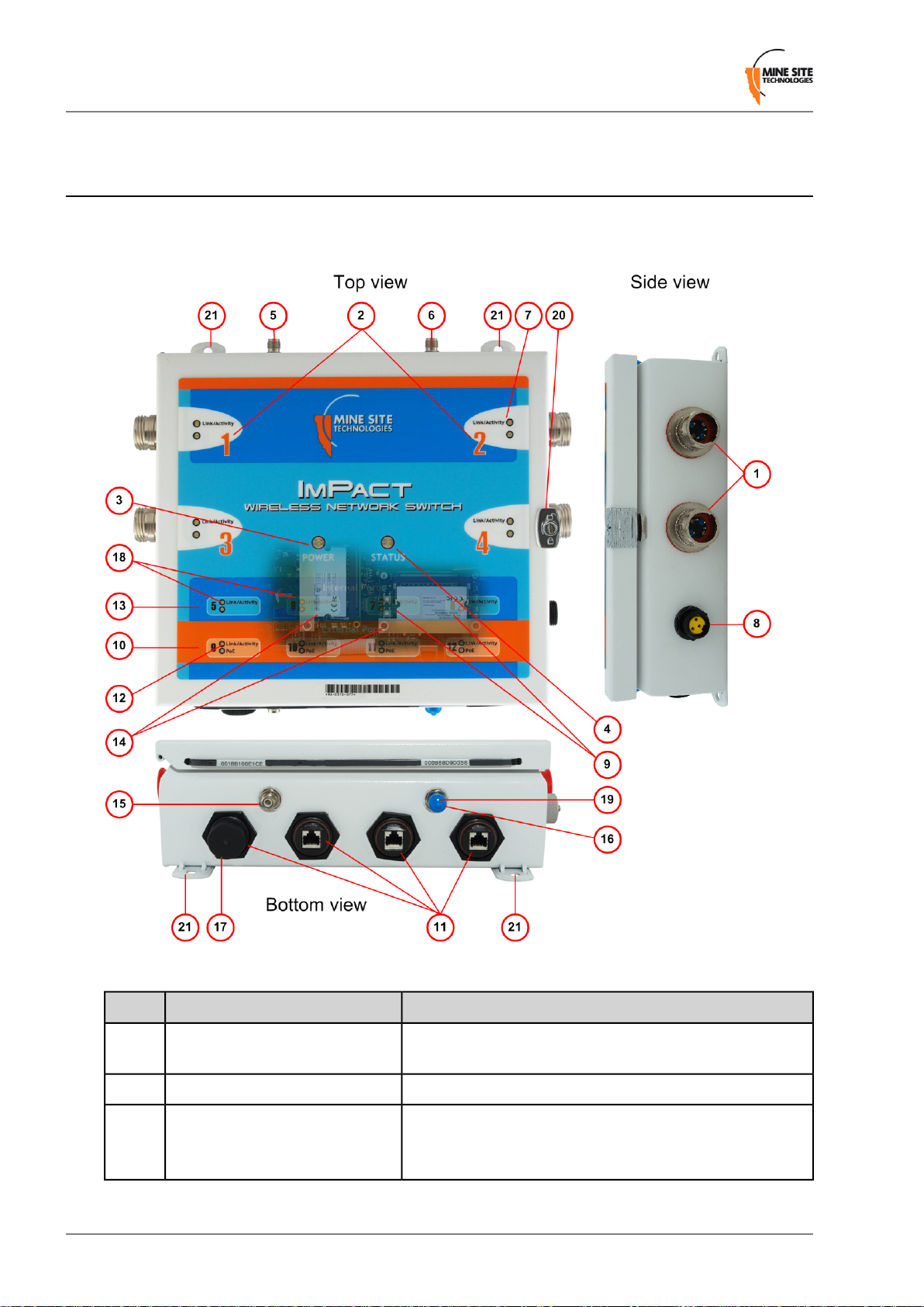
The features and functions of the WNS are illustrated in Figure 1: WNS layout and the accompanying
table.
Figure 1:WNS layout
1
Composite fibre / power cable
port
Power indicator LED3
FunctionDescriptionKey
Connector for data transmission and / or DC power
distribution.
Labelling of the fibre optic ports.Composite fibre port number2
• Green: when power is applied to the WNS.
• Red: when the power drops below 12V.
Revision A14Wireless Network Switch User Manual
Page 15

Understanding the Wireless Network Switch
FunctionDescriptionKey
Status indicator LED4
Fibre port Link / Activity LEDs7
8
9
External power insertion DC jack
(optional)
Internal Ethernet ports 7-8 Link /
Activity status LED
• Flashing Red: startup in progress.
• Flashing Green: normal operation.
• Solid Red: indicates an error.
• Off: indicates a problem (Refer to the Troubleshooting
Guide on page 101).
RP-TNC jack for connecting an antenna to Radio 2.MAIN antenna port for WAC 25
RP-TNC jack for connecting an antenna to Radio 2.AUX antenna port for WAC 26
• The top LED (green) flashes when data is transmitted or
received, and is solid when a link is established.
• The lower orange LED (orange) is active when the link
is running at 1Gbps.
An optional power inserter jack to connect to an additional
DC supply.
• The top LED (green) is lit when the internal ports have
established a link, and flashes when data is transmitted or
received.
• The lower LED (orange) is not used.
12
18
External Ethernet ports11
External Ethernet ports 9-12 Link
/ Activity status LED
Wireless Access14
Internal Ethernet ports 5-6 Link /
Activity status LED
Labelling of the Ethernet ports.External Ethernet port number10
External Ethernet with IEEE 802.3 af PoE supply capability
for powering WAPs and other network devices.
• The top LED (green) is lit when the internal ports have
established a link and flashes when data is transmitted
or received.
• The lower LED (orange) indicates that PoE power is
active.
Labelling of the Ethernet ports.Internal Ethernet port number13
Up to two internal wireless access cards (WACs) enabling
wireless network communication. The first WAC (located
on the left) is mandatory as it also manages the switch
processor.
RP-TNC jack for connecting an antenna to Radio 1.AUX antenna port for Radio 115
RP-TNC jack for connecting an antenna to Radio 1.MAIN antenna port for Radio 116
A protective cover when the Ethernet port is not in use.Ethernet port protective cover17
• The top LED (green) is shared between the radio card
and the first two internal ports (Radio 1 / Port 5 and Radio
2 / Port 6).
• The LED is active when either the Wi-Fi card or the
Ethernet has a link.
Wireless Network Switch User Manual15Revision A
Page 16
Understanding the Wireless Network Switch
FunctionDescriptionKey
• The LED flashes when data is transmitted or received.
• The lower LED (orange) will flash when a Wi-Fi tag is
detected by the radio card.
19
cover
Mounting holes21
A protective cover when the antenna jack is not in use.RP-TNC antenna jack protective
Lockable catch to prevent unauthorised access.Stainless steel enclosure lock20
Mounting holes for attaching to a WNS mounting plate for
installation.
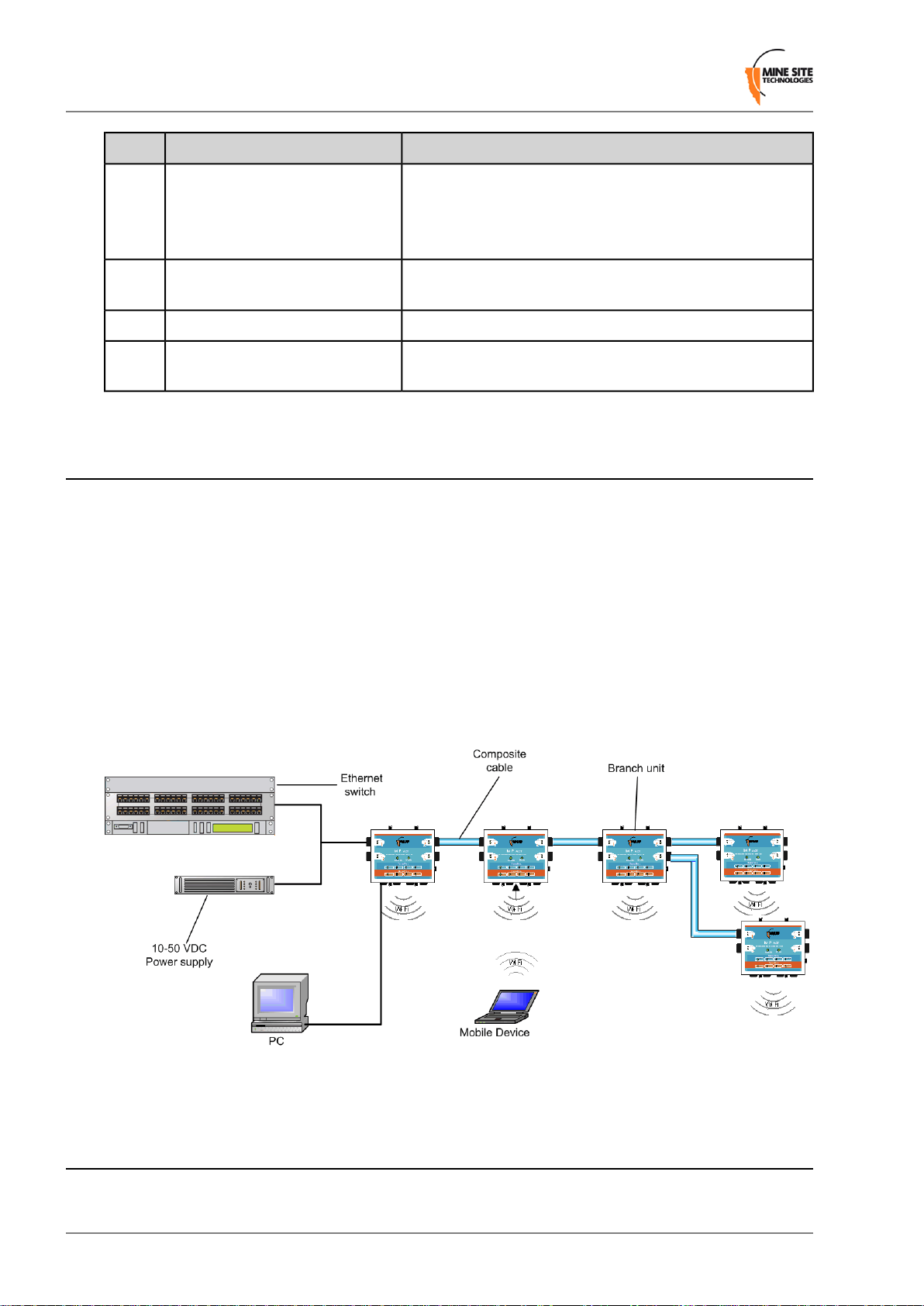
1.2 System Layout
WNS units are installed in a mine to form a wired and wireless network. This section describes a simple
WNS system layout in a mine as shown in Figure 2: Typical WNS system layout.
The first WNS in a network is connected to an Ethernet switch and power supply either by composite
cable (providing power and network connectivity) to the WNS, or connection to the WNS Ethernet port
and external power jack.
WNS units are typically connected in series down the mine tunnel by composite cable. When the mine
tunnel splits into different sections, an additional WNS is branched from the network. WNS or Wireless
Access Point (WAP) devices can also be positioned in Wi-Fi ‘hot spots’ such as crib areas and refuge
bays.
A PC or mobile device can connect to the network when in proximity of an WNS or WAP.
Figure 2:Typical WNS system layout
1.3 Connectivity
The WNS has three types of network connections:
Revision A16Wireless Network Switch User Manual
Page 17
Understanding the Wireless Network Switch
• Composite Fibre Ports
• Ethernet Ports
• Wireless
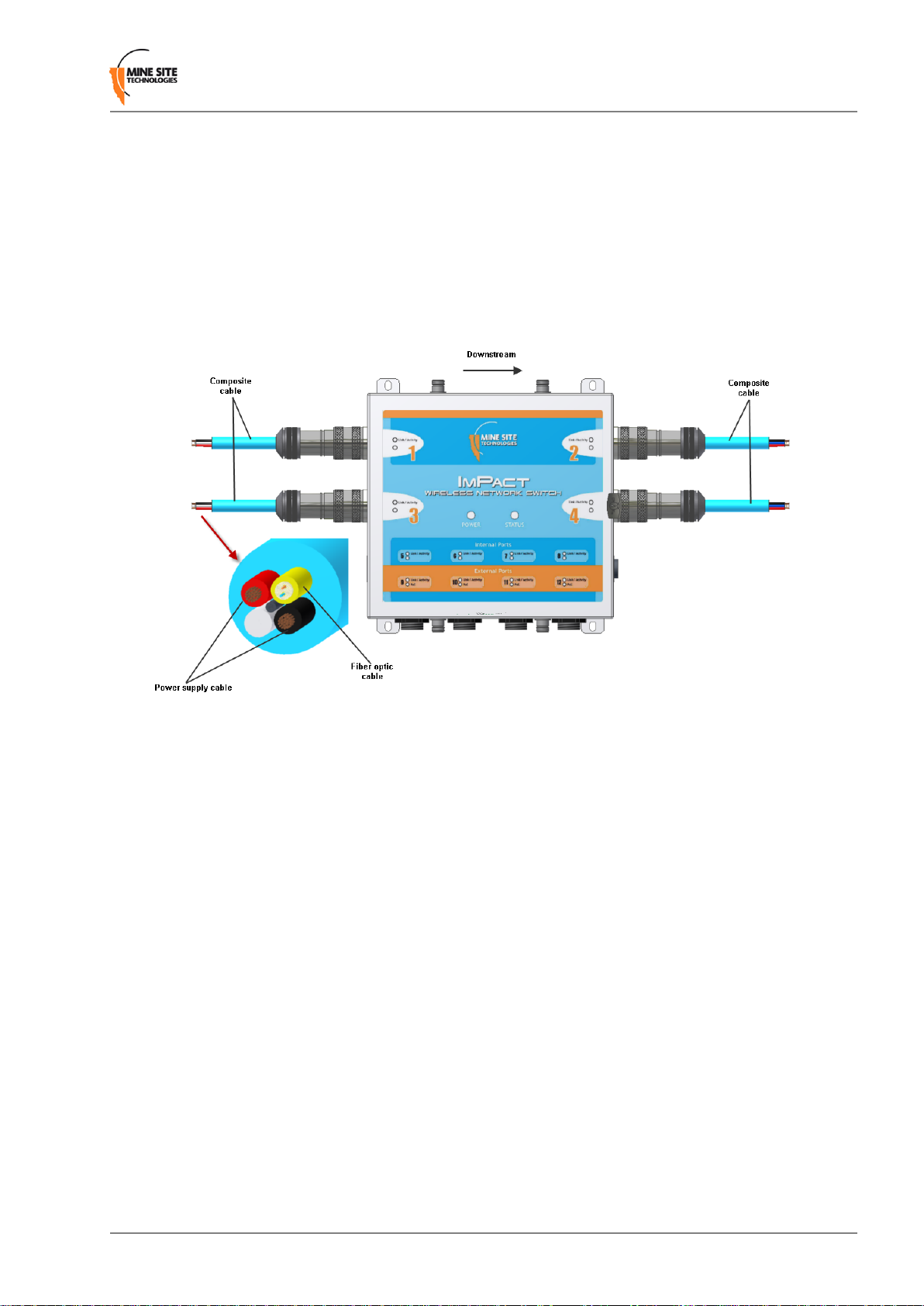
1.3.1 Composite Fibre Ports
WNS units have up to four composite fibre ports, interconnected by composite cables. The composite
cable contains fibre optic data cores and power (as shown in F igur e 3: WNS composite cable connection),
and connectors designed for durability in underground mines.
Figure 3:WNS composite cable connection
The composite cable overcomes the challenge of limited power access in mines by distributing power
between each WNS in a network. The fibre optic cable contained in the composite cable also provides
the following benefits over standard Ethernet cabling:
• WNS units can be spaced up to several kilometres apart, compared to Ethernet cabling with a distance
limitation of 100 metres. This reduces installation cost, component count and likelihood of faults.
• Fibre optic cable has superior signal integrity , with no signal interference from high powered electronics,
such as variable speed drives.
1.3.2 Ethernet Ports
The WNS has four optional internal Ethernet ports and four external Ethernet ports enabling connection
to client devices or other networking devices.
The four external Ethernet ports also provide IEEE 802.3 af PoE (Power over Ethernet) injector
functionality, allowing a single cable to be used for data and power to network devices. Each Ethernet
port's functionality can be configured by the web browser interface, or by centralised configuration
management. For more information on configuring Ethernet ports, see Configuring the VLAN Port Map
on page 65.
Wireless Network Switch User Manual17Revision A
Page 18

Understanding the Wireless Network Switch
1.3.3 Wireless Access
Wireless connectivity in each WNS is implemented using a WAC (Wireless Access Card), consisting of
a wireless network processor and an integrated mini PCI 802.11b/g adapter.
A WNS can contain up to two WACs. The WAC contained in the first radio card slot (on the left side)
also acts as the management CPU for the switch processor. As such, it is mandatory that this WAC is
fitted to each unit. The WA C operational parameters can be configured through the web browser interf ace
or by centralised configuration management. For more information, see Configuring Wireless Radio on
page 52 and Editing Site Configuration Files on page 87.
Revision A18Wireless Network Switch User Manual
Page 19

Chapter
2
Network System Design
Topics:
• Installation Types and Cov erage
• Power Requirements
• Choosing Antennas
• Placement of Wireless Network
Switches
• Placement of Antennas
• Determining Wi-Fi Distances
between Wireless Network
Switches
This chapter describes network system design for underground mines.
A MST System Engineer will usually design and preconfigure a
network based on the requirements and layout of each mine site. This
will involv e a visual inspection of the mine site to identify user areas,
and determine access point locations. A RF (Radio Frequency) site
survey is also conducted to understand the behaviour of radio waves
in the mine. The following factors help determine network design:
• Wireless coverage requirements of the mine
• Quantity and type of wireless client devices connected to the
network
• Wired client devices connected to the network and their location
• Interconnection to the mine's existing corporate network
• Policies for network protocol between networks
• Cabling requirements
• Antenna types to use with each unit and mounting method for each
antenna
• Mounting location and installation method for each network device.
Wireless Network Switch User Manual19Revision A
Page 20

Network System Design
2.1 Installation Types and Coverage
Wireless network coverage can be described as:
• Wi-Fi hotspot — Network coverage is provided in key areas, such as crib areas and refuge bays.
• Full coverage — Seamless wireless coverage by strate gically placing WNS units so their radio fields
overlap.
A WNS can communicate at wireless distances of 150-300 meters, depending on the geometry and geology
of the mine.
2.2 Power Requirements
The power requirements for a network are unique to each site installation. Determining power requirements
can be complex and is dependent on various factors such as the number of WNS units, PoE devices,
branches in the network and composite cable lengths.
Note: A site inspection conducted by a MST System Engineer will help determine the power
requirements for your network.
The WNS is designed to operate at a wide voltage range, from a minimum of 10VDC up to 50VDC. Each
WNS in a network can internally step up the incoming voltage to 48VDC in order to supply power to
connected PoE devices. The WNS needs to recei v e a minimum input of 15VDC to po wer connected PoE
devices.
48VDC power supplies are used for large networks to maximise the distance between power supplies.
For smaller networks of 1-2 nodes, it is recommended that a lower v oltage 24VDC po wer supply is used.
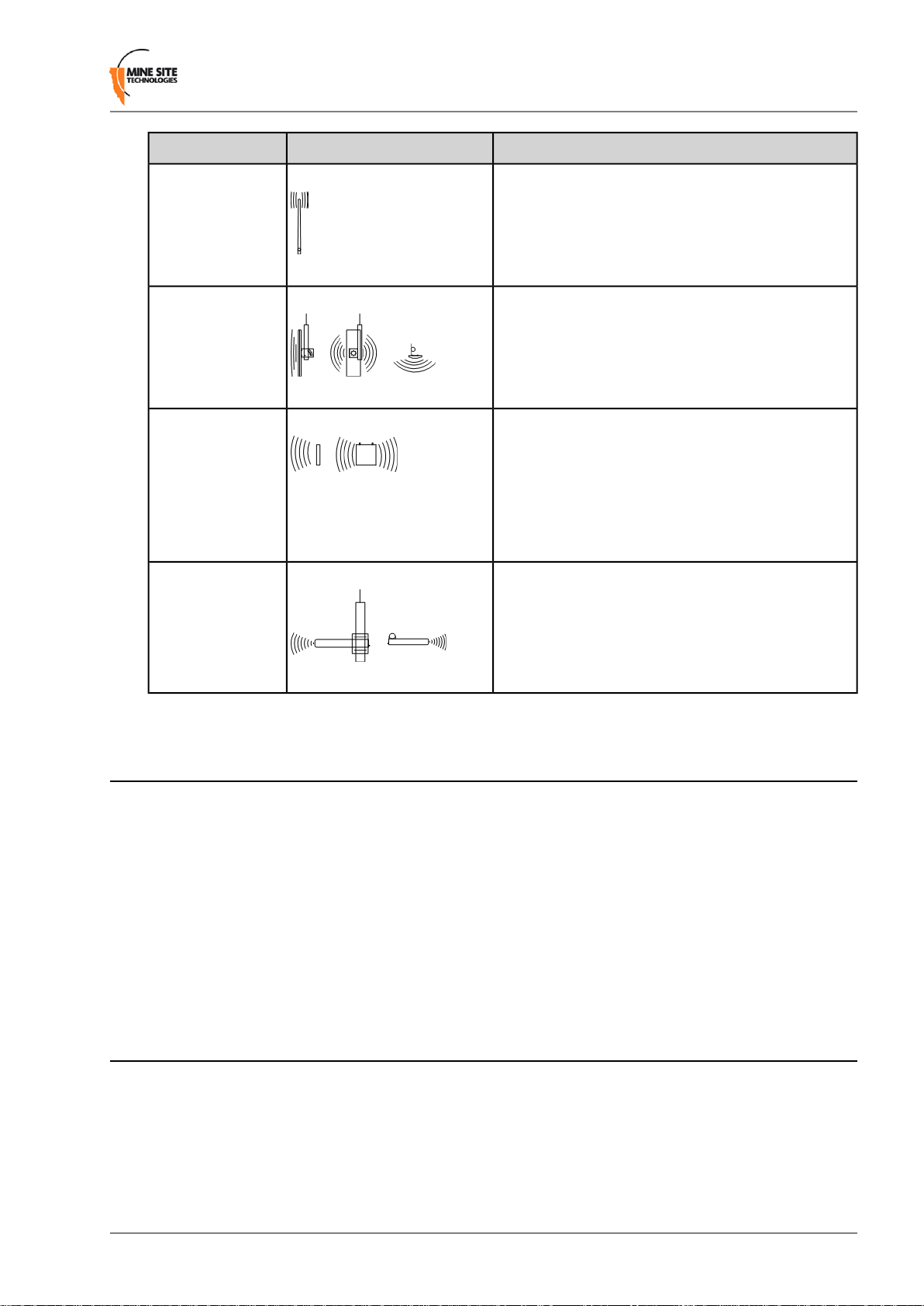
2.3 Choosing Antennas
Antennas are connected to each WNS to provide wireless network co verage. The type of wireless cov erage,
surrounding geology, tunnel topology and stratum type are factors that will determine the choice of
antenna. A minimum of one antenna is required per WAC in a WNS.
Antennas consist of two directional patterns:
• Omnidirectional antennas — radiate equally in all directions for a short range, providing immediate
coverage in an open area.
• Directional antennas — radiate in a specific direction over a longer range. A higher gain antenna
will have a longer range and is more directional. It is important that directional antennas are aligned
properly between WNS units.
The antenna radiation pattern and polarisation need to be considered to provide suitable wireless coverage
in an area.
Antennas commonly used with the WNS are shown below.
Revision A20Wireless Network Switch User Manual
Page 21
Network System Design
DescriptionIllustrationAntenna Type
Omnidirectional
5.5dbi rubber
whips
Panel antenna
Diversity panel
antenna
Yagi directional
antenna
A lower gain antenna that radiates equally in all
directions. It provides direct coverage in an open area.
A panel antenna is a directional antenna, with a wide
horizontal beamwidth and narrower vertical
beamwidth. They are suited for cov ering an open area
in one direction.
A diversity panel antenna contains two panel antennas
in one housing with a 90° rotation between them. It
is used for providing better signal reception in
difficult areas, and more accurate AeroScout® tag
location when Wi-Fi tracking is implemented.
Diversity antennas use both antenna connections on
a WAC.
A Yagi antenna is high gain directional antenna. They
are ideally suited for line of sight tunnel
communications. Yagi antennas need to be aimed
accurately and avoid obstacles in their RF beam path.
2.4 Placement of Wireless Network Switches
A site inspection will determine the best positioning of cables, WNS units and antennas prior to installation.
WNS units with antennas directly attached should be mounted in an elevated position, within line-of-sight
of mobile devices. Ideally this would be situated high up on a tunnel ceiling or on the rock wall face. The
mounting location should be free from debris, and avoid obstruction to vehicles, equipment/machinery,
vent tubing and cables.
WNS units should not be installed in cut-out areas such as safety bays and remuck bays, due to signal
confinement. In such instances, a WAP is more suitable, connected to the nearest WNS. For details on
common WNS mounting scenarios, see WNS Mounting Options on page 26.
2.5 Placement of Antennas
Antennas are usually mounted separately from each WNS to optimise transmission and avoid any
obstructions in a tunnel. They are connected by coaxial cable. The coaxial connection should be kept as
short as possible to minimise signal attenuation. Larger antennas / longer cable feeds can require line
amplifiers, and possibly bi-directional splitter / combiners for dual antenna systems.
Antenna placement is dependent on the surrounding geology, tunnel topology and stratum type. The
recommended placement of antennas is as follows:
Wireless Network Switch User Manual21Revision A
Page 22
Network System Design
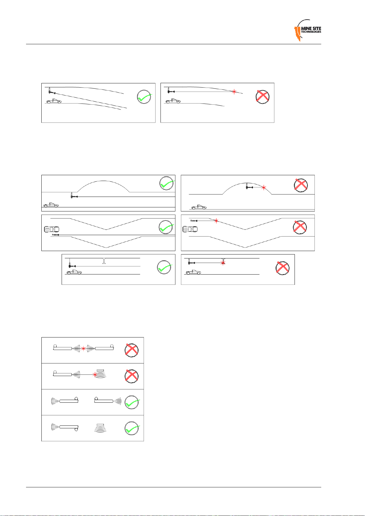
Tip 1: Directionality
Antennas should be mounted and angled to give optimum transmission along curves and dips as shown
below in Figure 4: Angling antennas.
Figure 4: Angling antennas
Tip 2: Obstructions
Antennas should be mounted to avoid signal obstruction from rock, vehicles, equipment and machinery
as shown in Figure 5: Antenna mounting to avoid obstructions.
Figure 5: Antenna mounting to avoid obstructions
Tip 3: RF Field Overlap
Multiple antennas should be mounted to avoid crossing signal paths as shown in Figure 6: Antenna
directivity.
Figure 6: Antenna directivity
Revision A22Wireless Network Switch User Manual
Page 23
Network System Design
The positioning of the antennas is crucial when AeroScout® tags are used for asset tracking and location
services. AeroScout® tags will not be read when there are antenna standing wave nulls. Antennas need
to be positioned to have best reception of tag messages.
For Antenna mounting options, see Antenna Mounting Options on page 27.
2.6 Determining Wi-Fi Distances between Wireless Network Switches
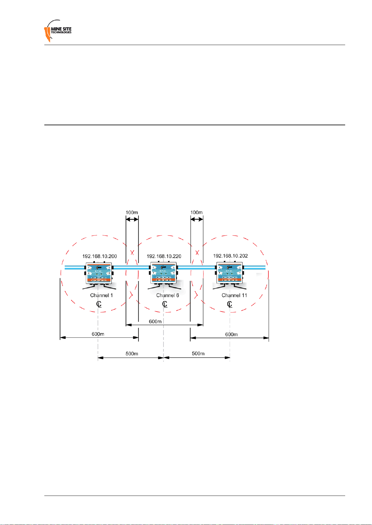
2.6.1 Line of Sight Distances
In line of sight, a WNS has a maximum wireless range of 300 metres (984 feet) using high gain directional
antennas. WNS units are generally installed with a 100 metre (328 feet) overlap of the radio field as sho wn
in Figur e 7: Wireless channel layout and distances. This ensures sufficient cov erage between WNS units.
WNS units within range of each other must be configured with different W i-Fi channels. By default e very
fifth channel is used (channels 1, 6 and 11) to prevent signal overlap, minimising the possibility of
inter-modulation or interference.
Figure 7:Wireless channel layout and distances
2.6.2 Distances Around Curves
The wireless range of a WNS decreases when going around curves. In this case, WNS units need to be
installed closer together to provide sufficient coverage. Distances between WNS units will vary depending
on the drift and tightness of the curve. They are installed closer together on a tight curve.
Use the following steps to estimate the distance between WNS units:
1. Install one WNS unit at the beginning of the curve.
2. Install the second WNS unit between 20 metres (65 feet) to 40 metres (130 feet) from the end of the
curve.
3. Perform a RF signal strength test by walking from the first WNS to the second WNS.
4. If the strength test records levels of:
Wireless Network Switch User Manual23Revision A
Page 24

Network System Design
• -80 to -65, the WNS units are spaced for optimal coverage.
• -81 to -100, move the second WNS closer (at 10m interv als), and conduct another RF signal strength
test.
• -64 to -10, move the second WNS further away, and conduct another RF signal strength test.
Revision A24Wireless Network Switch User Manual
Page 25

Chapter
3
Installation
Topics:
• WNS Mounting Options
• Antenna Mounting Options
• Installation Schemes
• Connecting Power to the
Wireless Network Switch
• Handling Composite Cable
During Installation
• Connecting Composite Cable to
the Wireless Network Switch
• Connecting Ethernet Cable to
the Wireless Network Switch
• Connecting Antennas to the
Wireless Network Switch
• Manual Reset and Reboot
This chapter describes WNS and antenna mounting options, installation
schemes, antenna and cable connections. Fibre connector assembly
and cable termination in the WNS are beyond the scope of this manual.
Important: The electronic components in a WNS are designed
to be isolated from the enclosure and local electrical earth. This
ensures there is no current passing between grounds of different
potentials (known as galvanic isolation). Galv anic isolation must
always be maintained, with the WNS ground terminals isolated
from electrical earth, and all antenna and antenna cable
connections properly insulated.
Wireless Network Switch User Manual25Revision A
Page 26
Installation
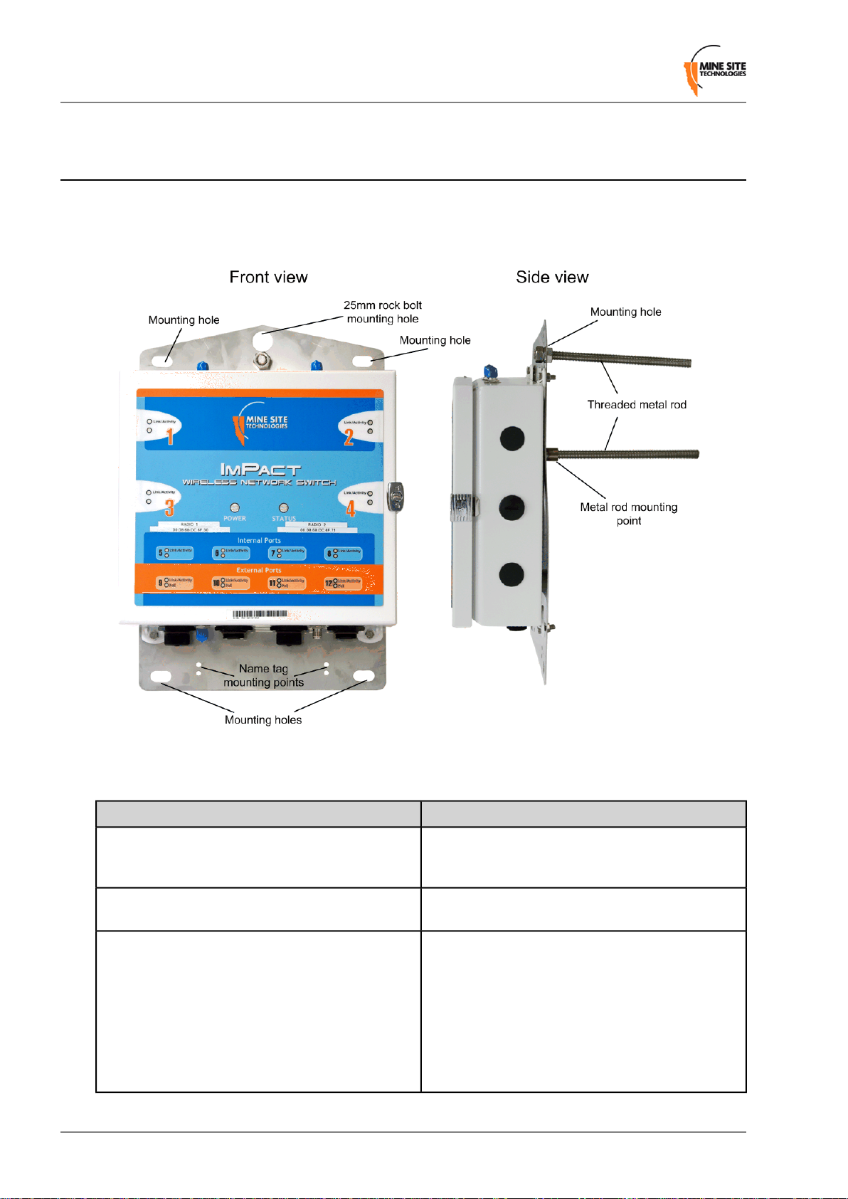
3.1 WNS Mounting Options
A WNS can be attached to a WNS mounting plate with M6 bolts and nuts as shown in Figure 8: WNS
on a mounting plate. The WNS mounting plate has the fle xibility to mount the WNS in a mine in v arious
configurations.
Figure 8:WNS on a mounting plate
Standard mounting options for the WNS using the mounting plate are described in the table below.
InstallationApplication
Mounting the WNS to a rock bolt
Mounting the WNS to the mesh
Mounting the WNS into the rock face
The WNS mounting plate has a 25mm hole to mount to
a rock bolt in the mine's rock face. The mounting plate is
secured to the rock bolt with a 25mm nut.
The four corner mounting points on a mounting plate can
be cable-tied to the mesh in a mine tunnel.
A WNS can be directly mounted to the rock face using
the mounting plate and two threaded metal rods. A
threaded rod is screwed to the mounting point on the back
of the mounting plate. The second metal rod is secured
at the top of the mounting plate with two nuts as shown
in Figure 8: WNS on a mounting plate. Two holes are
drilled into the rock face and the mounting plate is
inserted into the rock face and secured with chemset
adhesive.
Revision A26Wireless Network Switch User Manual
Page 27
3.2 Antenna Mounting Options
Antenna mounting is dependent on the location and coverage required. Examples of antenna installation
options are described and illustrated in the table below.
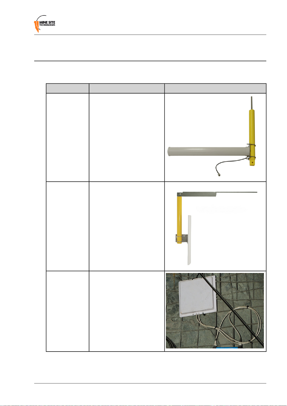
PictureDescriptionMounting Option
Installation
Mounting a Yagi
antenna or panel
antenna to the mine
tunnel roof.
Mounting a Yagi
antenna or panel
antenna in a stope
or tunnel entrance.
1. The Yagi antenna is attached to
the mounting pole using
U-clamps and nuts.
2. A threaded metal bar is screwed
into the mounting pole.
3. A hole is drilled into the tunnel
roof and the mounting pole is
secured using chemset
adhesive.
1. The Yagi antenna or panel
antenna is attached to the
mounting pole using U-clamps
and nuts.
2. The mounting pole is bolted to
a metal bracket.
3. The metal bracket is bolted to
a mine tunnel entrance or roof
using three M12 Dynabolts.
This mounting method enables
angling of the antenna into a
mine tunnel or stope.
Mounting a
diversity panel
antenna on the
rockface.
Diversity panel antenna is cable
tied the mesh.
Wireless Network Switch User Manual27Revision A
Page 28

Installation
3.3 Installation Schemes
The installation and placement of antennas and WNS units will depend on the wireless coverage type,
rock type and tunnel topology. A few examples of installation schemes in a mine are described and
illustrated in the following sections.
3.3.1 Installation in a Straight Drive
An example of a straight drive installation scheme is sho wn in Figure 9: Installation scheme in a straight
drive.
• Two Yagi antennas are clamped to a mounting pole, which is chemically adhered into the mine roof.
• The antennas are positioned in opposite directions to provide long range wireless coverage.
• Each antenna is connected to a separate WAC in the WNS, or a Wi-Fi signal splitter can be used to
split the signal from one WAC in two directions.
• The network switch is cable tied to the rock mesh and connected to the composite cable that provides
power and network connectivity.
Revision A28Wireless Network Switch User Manual
Page 29
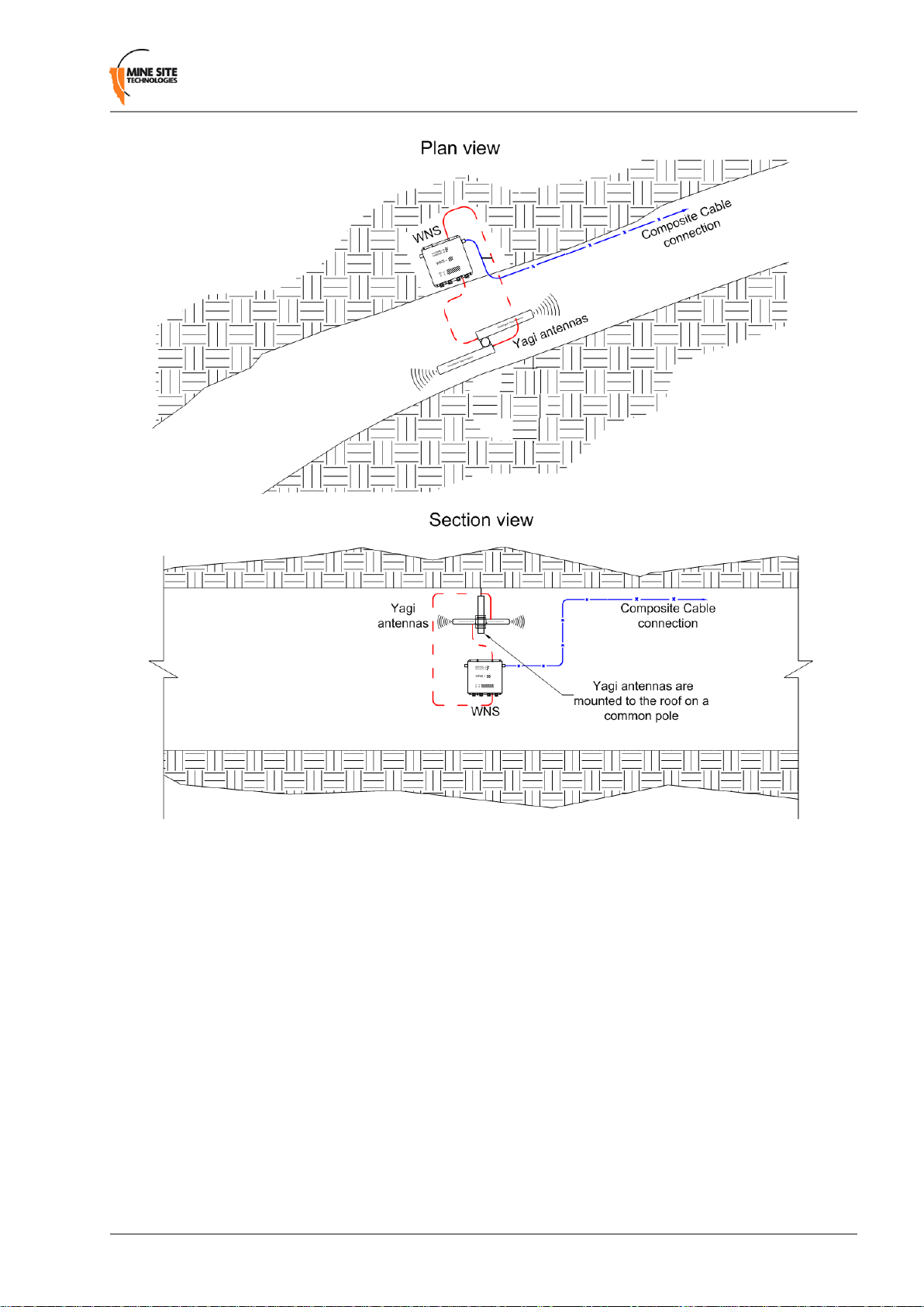
Installation
Figure 9: Installation scheme in a straight drive
3.3.2 Installation in a Curved Decline / Incline
A curved decline / incline installation scheme is shown in Figure 10: Installation scheme in a curved
decline / incline.
• A Yagi antenna is positioned at the end of the curve for directional wireless coverage.
• The Yagi antenna is clamped to a mounting pole, and is chemically adhered into the mine roof.
• A panel antenna is roof mounted in the middle of the curve providing wide wireless coverage.
• Each antenna is connected to a WAC in the WNS.
• The network switch is cable tied to the rock mesh, connected to the composite cable that provides
power and network connectivity.
• The network switch is also a link for power and network connectivity to devices in the next location.
Wireless Network Switch User Manual29Revision A
Page 30
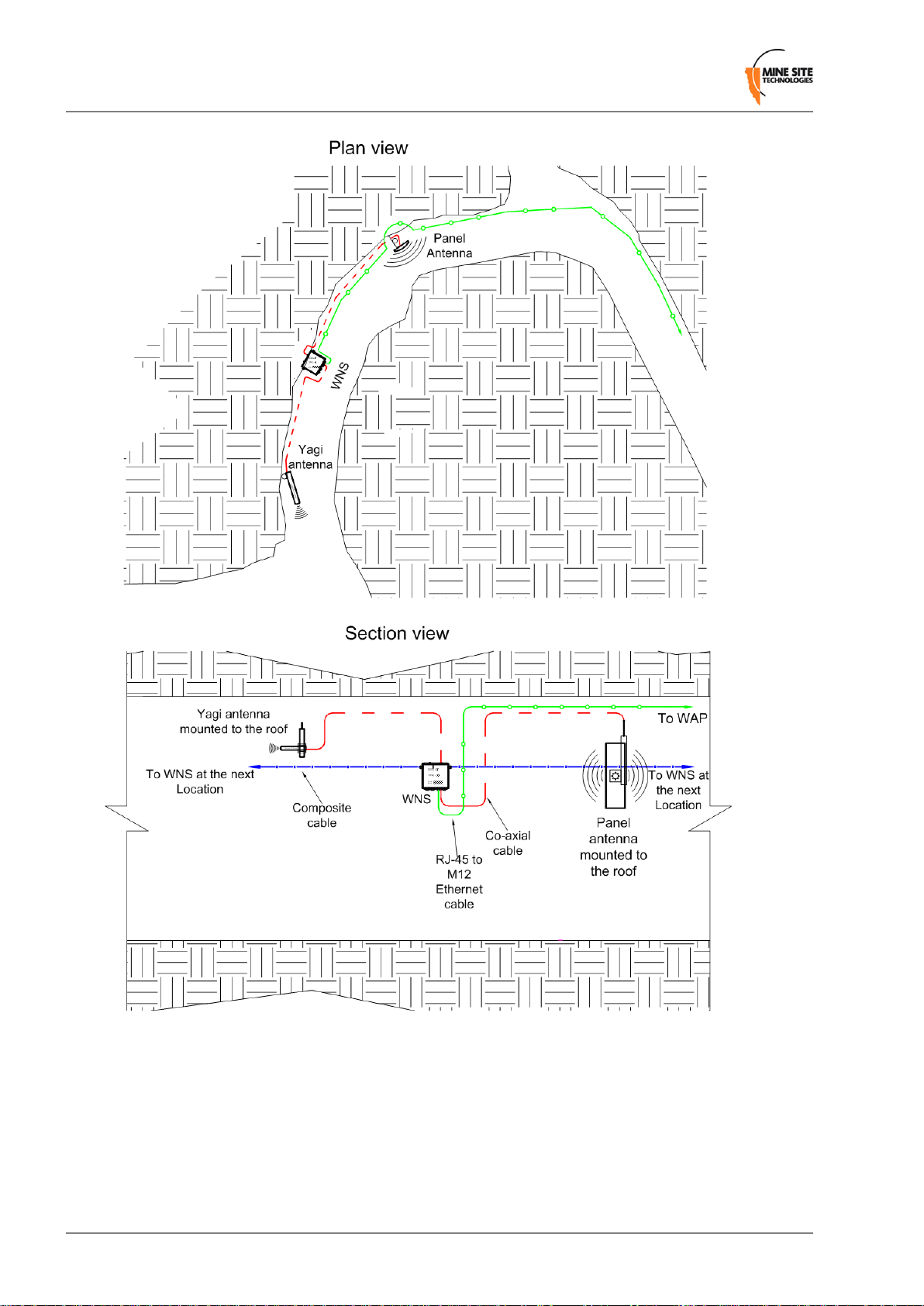
Installation
Figure 10: Installation scheme in a curved decline / incline
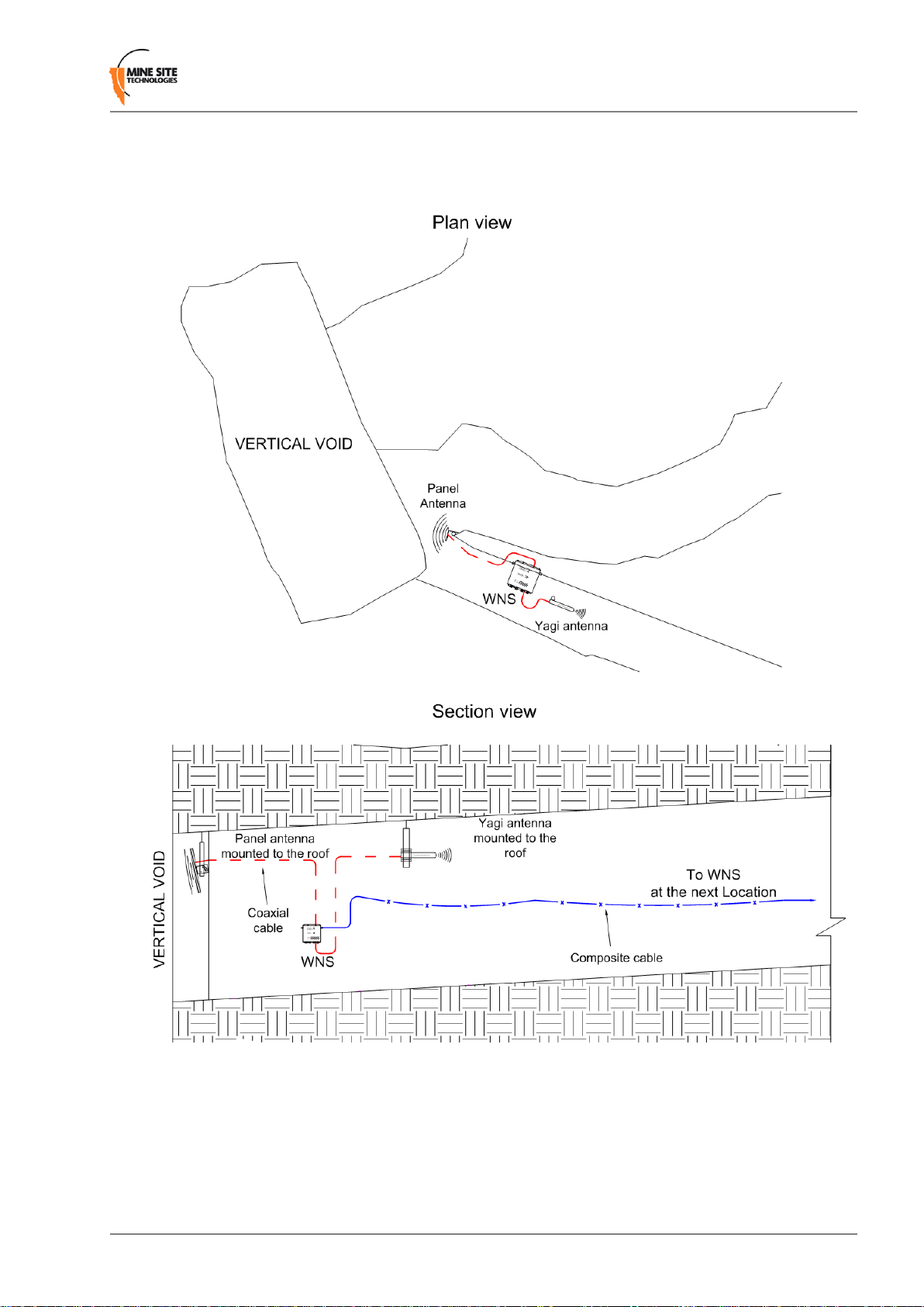
3.3.3 Installation in a Stope
An installation scheme for a stope is shown in Figure 11: Installation scheme in a stope.
• A panel antenna is clamped to a mounting pole, and is chemically adhered into the mine roof.
• The panel antenna is angled down into the stope to provide wide wireless coverage.
• A Yagi antenna is installed in the roof providing directional coverage down a straight drive.
Revision A30Wireless Network Switch User Manual
Page 31
Installation
• Each antenna is connected to a WAC in the WNS. The network switch on a mounting plate is attached
to a rock bolt.
• The composite cable supplies power and network connectivity to the switch.
Figure 11: Installation scheme in a stope
3.3.4 Installation at an Intersection
An example installation scheme for an intersection is shown in Figure 12: Installation Scheme at an
intersection.
Wireless Network Switch User Manual31Revision A
Page 32

Installation
• A panel antenna is clamped to a mounting pole, and is chemically adhered into the mine roof.
• The panel antenna is angled to provide wide wireless coverage at an intersection.
• A Yagi antenna is installed in the roof providing directional coverage down a straight drive. Each
antenna is connected to a WAC in the WNS.
• The network switch is cable tied to the rock mesh, connected to the composite cable that provides
power and network connectivity.
• The network switch also acts as a link for power and network connectivity to devices in the next
location.
Revision A32Wireless Network Switch User Manual
Page 33

Installation
Figure 12: Installation Scheme at an intersection
3.4 Connecting Power to the Wireless Network Switch
A pre-deployment power-up test of WNS units is recommended. To conduct a power-up test:
Wireless Network Switch User Manual33Revision A
Page 34

Installation
1. Connect the composite fibre/power cable to a DC power source with correct termination. Note that the
DC supply must be between 10 and 50VDC.
2. Turn on the DC power supply and verify that the green power light is lit.
Power can be applied to cabling whilst additional WNS units are being installed. Power usage levels
should be evaluated prior to adding more units downstream to ensure that the voltage rail does not drop
too low. A minimum of 15VDC is required for a WNS to supply PoE to other devices. If the voltage
drops below 15V, a power inserter is required.
3.4.1 Installing Additional Power
Power inserters may be necessary to provide additional po wer in a large network or when there are branch
WNS units. This additional power can be inserted via the DC jack on the WNS as shown in Figure 13:
Power inserter DC jack.
Figure 13: Power inserter DC jack
3.5 Handling Composite Cable During Installation
The composite cable is ruggedly built for the mining environment. However the following precautionary
measures should be noted during installation:
• Never pull or create tension on the cable. Unreel the cable from the cable reel, or allow the weight of
the cable to unreel as the vehicle is moving as shown in Figure 14: Handling composite cable.
• Do not be bend the cable at sharp angles; excessive bending can fracture or break the fibre optic cable.
• Do not step on the cable.
Revision A34Wireless Network Switch User Manual
Page 35

Figure 14: Handling composite cable
3.6 Connecting Composite Cable to the Wireless Network Switch
A composite cable connection requires connecting the composite cable connector to the fibre port of the
WNS as shown in Figure 15: Composite cable connector and Fibre port. Once the WNS is connected,
it will auto detect devices and their settings.
Installation
Figure 15: Composite cable connector and Fibre port
The following procedure outlines composite cable connection when there is power being supplied
downstream in the network.
Important: Protect all connectors and sockets from dust and grit, with minimal exposure during
installation. Any unused sockets must be covered by the supplied dust caps at all times.
1. Remove the dust cap from the fibre port socket.
Wireless Network Switch User Manual35Revision A
Page 36

Installation
2. Align the composite cable connector to the locating notch on the fibre port socket as shown in Figure
15: Composite cable connector and Fibre port and insert firmly.
3. Screw the outer sleeve of the composite cable connector securely to the fibre port socket. The power
LED will turn on, and corresponding fibre port link LED will light up green. The port activity LED
will flash with network activity.
4. Repeat step 2 and 3 for connecting downstream cables.
5. If a WNS is installed at the other end of the downstream cable, the fibre link LED will light up green.
The fibre activity LED will flash with network activity.
Connecting a WNS to a branch WNS requires simply connecting composite cables to the additional fibre
ports. The connected fibre ports will cause the corresponding fibre port LEDs to become active. If you
are adding WNS units to an existing system, please consult your MST System Engineer to ensure power
requirements are being met.
3.7 Connecting Ethernet Cable to the Wireless Network Switch
The external Ethernet ports are located on the underside of the WNS, and are used to connect to Ethernet
devices (such as Laptop computers, Ethernet controlled PLCs, hard-wired Ethernet Phones and IP video
devices). An Ethernet cable with a RJ45 connector is used to connect PoE devices. Ethernet cables are
required to meet specifications for use in a mining environment in Ethernet Cable Specifications on page
105.
The following procedure demonstrates how to connect an Ethernet cable to the WNS.
IllustrationProcedureStep
1
Check the Ethernet cable has a
RJ45 protective cover attached.
Revision A36Wireless Network Switch User Manual
Page 37

Installation
IllustrationProcedureStep
2
3
Unscrew the RJ45 cover on the
Ethernet port.
Insert connector into the Ethernet
port.
4
Screw the RJ45 protective cover
on the cable to the mating jack on
the WNS.
Important: Check that all
unused Ethernet ports
remain protected with the
supplied covers.
Wireless Network Switch User Manual37Revision A
Page 38

Installation
IllustrationProcedureStep
5
Securely fasten the cable lead
against the wall/ceiling.
3.8 Connecting Antennas to the Wireless Network Switch
Antennas can be connected directly to the antenna (RP-TNC) jacks on the WNS or mounted remotely to
the WNS by using coaxial cables. Coaxial cable length should be kept as short as possible (ideally less
than 10m) to minimise signal loss.
Important: All cable and antenna connections must be electrically insulated using
self-amalgamating rubber tape.
The following procedure describes how to connect a coaxial cable to the WNS and electrically insulate
the connection.
IllustrationProcedureStep
1
Remove the antenna port dust cap
from the antenna port.
Revision A38Wireless Network Switch User Manual
Page 39

Installation
IllustrationProcedureStep
2
3
Connect the coaxial cable plug to
the RP-TNC jack on the WNS and
tighten the outer sleeve.
Insulate the connection using
self-amalgamating rubber tape.
Start at the base of the connection
and pull back the rubber tape
backing.
4
5
Pull the tape tightly, and tape
around the connector at an angle
until it is 25mm past the end of the
connection.
Wind the rubber tape at an angle
back down towards the base of the
connection and cut the tape.
Wireless Network Switch User Manual39Revision A
Page 40

Installation
IllustrationProcedureStep
6
Cable tie and mount the coaxial
cable(s) so it is free from
obstructions.
Important: Check that all
unused antenna ports
remain covered with the
supplied dust caps. Check
there are no obstructions
near the antennas that could
hinder the radiation pattern.
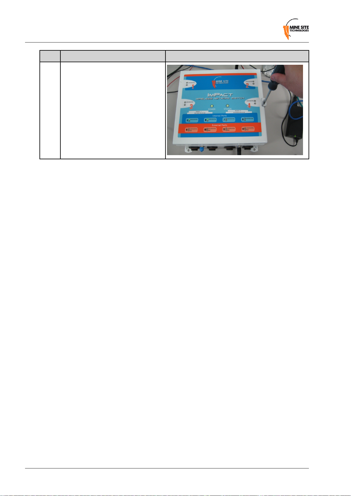
3.9 Manual Reset and Reboot
The WNS can be manually power cycled or reset to factory default settings as described below. Care
should be taken to avoid any dust, water or foreign particles entering the enclosure when opening.
PictureDescriptionStep
1
2
Open the WNS enclosure using a flat
head screwdriv er to unlock the lid lock.
Locate and identify the Reset button
labelled "S1" and Default button
labelled "S2" on each Wireless Access
Card (WAC).
Revision A40Wireless Network Switch User Manual
Page 41

Installation
PictureDescriptionStep
3
4
To reset the WNS (i.e. power cycle),
press and release the S1 button on either
WAC whilst the unit is powered up.
T o reset to factory default settings whilst
the unit is powered up, press and hold
both the S1 and S2 button on the WAC.
Release S1 while continuing to hold the
S2 button for another 5 seconds.
Note: This procedure must be
performed on each WAC to reset
to factory default settings.
Wireless Network Switch User Manual41Revision A
Page 42
Installation
PictureDescriptionStep
5
Close the lid on the WNS and secure the
lid lock using a flat head screwdriver.
Revision A42Wireless Network Switch User Manual
Page 43

Chapter
4
Understanding VLANs
Topics:
• Understanding Trunk and
Access Ports
• VLANs and Wireless Networks
• Native VLAN
This chapter explains the principles behind a Virtual Local Area
Network (VLAN). It is important to understand VLANs to properly
configure a WNS.
A VLAN is a collection of nodes grouped according to their function
or application, rather than their physical location. They are grouped
in order to separate and prioritise data within a network, as shown in
Figure 16: VLANs. VLANs are created when multiple applications,
such as voice, telemetry, data and video, are required in a mining
network.
Figure 16:VLANs
Wireless Network Switch User Manual43Revision A
Page 44

Understanding VLANs
4.1 Understanding Trunk and Access Ports
VLANs can be assigned to trunk ports and access ports on a network. These two types of port allocations
determine how data is transmitted and relayed.
4.1.1 Trunk Ports
Trunk ports provide a connection between network switches and access points, and can be assigned to
multiple VLANs. They will only transmit frames (packets of data) that belong to the port's assigned
VLANs. To identify the frames, a network switch will add a tag to the frame (known as 802.1q trunking).
The tag contains the following information:
• VLAN ID — allows the network switch receiving a frame to identify the VLAN it belongs to.
• Priority ID — allows the network switch to prioritise distribution when multiple frames are being
transmitted. Priority ID ranges from 0-7, where 7 is the highest priority.
When a network switch receives a tagged frame, the tag is read to determine the VLAN it belongs to. The
tag is removed and distributed to devices connected on the same VLAN. If a tagged frame is sent to a
trunk port with a different VLAN ID not assigned to the port, it will be dropped.
When the network switch receives multiple frames, it will prioritise the distribution of frames based on
the Priority ID in the VLAN ID tag. For more information on configuring VLANs, see Defining VLANs
on page 63.
4.1.2 Access Ports
Access ports connect client devices such as PCs and laptops to the network switch, and can only be
assigned to a single VLAN. Access ports can only send and receive untagged frames belonging to the
assigned VLAN. Any tagged frames sent to an access port will be dropped.
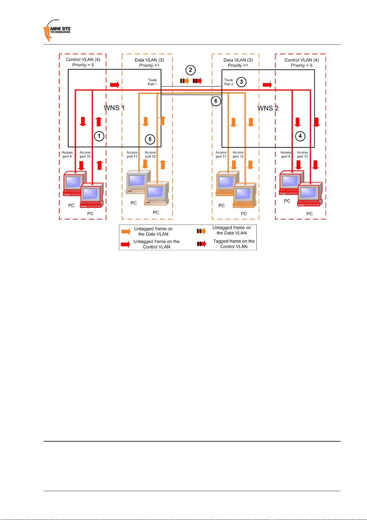
An example of VLAN traffic flow through trunk and access ports is shown in Figure 17: VLAN traffic
flow and described below.
Revision A44Wireless Network Switch User Manual
Page 45
Understanding VLANs
Figure 17:VLAN traffic flow
1. A PC sends an untagged frame on access port 10 (Control VLAN) on WNS 1. The frame is sent to
other access ports on the Control VLAN (access port 9).
2. WNS 1 tags the frame with VLAN ID = 4 and Priority = 5 and sends it through the trunk ports to WNS
2.
3. WNS 2 receives the tagged frame, and identifies the frame belonging to the Control VLAN.
4. WNS 2 removes the tag and sends the frame to all ports on the Control VLAN (access ports 9 and 10).
5. If WNS 1 receives multiple frames, they are tagged and sent via trunk ports to WNS 2.
6. WNS 2 receives the frames and prioritises distribution.
4.1.3 Port Allocation
Physical ports on the WNS can be configured to be either a trunk port or access port using the web browser
interface or editing site configuration files when T ri vial File Transfer Protocol (TFTP) is used. The WNS
default configuration has ports 1-4 and 9-12 allocated as trunk ports. Ports 1-4 are usually connected to
other WNS units, and ports 9-12 are connected to WAPs or other PoE devices. For more information on
configuring ports and VLAN membership, see Configuring the VLAN Port Map on page 65.
4.2 VLANs and Wireless Networks
The WNS can hav e up to four wireless Service Set Identifiers (SSIDs) per WA C. Each SSID is associated
with a single VLAN and functions as an access port on that VLAN. An example of a wireless network
is shown in Figure 18: An example of VLAN and wireless networks and described below.
Wireless Network Switch User Manual45Revision A
Page 46

Understanding VLANs
Figure 18: An example of VLAN and wireless networks
1. An untagged frame is sent from a Laptop 1 through a wireless network (SSID = Data) on the WNS.
2. The frame is tagged by the WNS and is sent through the trunk port to the WAP.
3. The WAP identifies the tagged frame as belonging to the Data VLAN and removes the tag.
4. The untagged frame is sent via the wireless network (SSID = Data) to Laptop 2.
4.3 Native VLAN
Trunk ports on a WNS also support a Native VLAN. The Native VLAN is where untagged frames will
be allocated. On the WNS, the nativ e VLAN is always the Infrastructure VLAN. This allo ws client devices
such as PCs or laptops to access and manage a WNS when they are connected via a trunk port.
The Infrastructure VLAN is mandatory in the WNS and cannot be deleted.
An example of native VLAN functionality is illustrated in Figure 19: An example of native VLAN and
described below.
Revision A46Wireless Network Switch User Manual
Page 47

Understanding VLANs
Figure 19: An example of native VLAN
1. The PC sends an untagged frame to Trunk port 3 on WNS 1.
2. The frame is allocated to the Infrastructure VLAN.
3. The management CPU of WNS 1 is always an Access port on the Infrastructure VLAN and will receiv e
the frame.
4. The untagged frame would also go to WNS 2 via the Trunk ports between the WNS units.
5. WNS 2 allocates the untagged frame to the Infrastructure VLAN.
6. The management CPU of WNS2 is always an Access port on the Infrastructure VLAN and will recei ve
the frame.
7. Any frame leaving the Management CPU is placed on the Infrastructure VLAN.
8. All frames on the Infrastructure VLAN are sent out untagged on Trunk ports.
Wireless Network Switch User Manual47Revision A
Page 48

Page 49

Chapter
5
Configuration Using the Web Interface
Topics:
• Logging onto the Web Browser
Interface
• Configuration screen
• Basic Tab
• Advanced Tab
• Tools Tab
• Status Tab
This chapter describes configuring an ImPact network device using a
web browser. Screenshots apply to devices with firmware version
2.22.0.
The ImPact WNS and WAP have a built-in web-server that is
accessible by a PC to configure settings. A PC can access the web
browser interface by making a TCP/IP connection to the device. For
more information, see Connecting a PC to an ImP act Network Device.
The IP address of the network device can be located and configured
using the Ubidevman device disco v ery tool. F or more information on
how to use Ubidevman, see Discovering Devices on the Network.
Wireless Network Switch User Manual49Revision A
Page 50

Configuration Using the Web Interface
5.1 Logging onto the Web Browser Interface
The web browser interface has a login front screen with access at two levels:
• ADMIN — Allows settings to be viewed and modified. The default password is ‘admin’.
• USER — Allows settings to be viewed but not modified. By default there is no password.
Note: Login and configuration needs to be carried out for each WAC fitted to a WNS. Each WAC
has a unique MAC address and should be configured with a unique IP address.
To log in to the web browser interface:
1. Launch your web browser and enter http://<WA C IP address> in the address field. The factory def ault
IP address is http://192.168.1.90 for WNS units.
2. The WNS login screen is displayed.
3. In the LOGIN dialog box, select Admin from the User Name drop-down box, and type the password
in the Password field. The factory default password is admin.
4. Click Log In. The configuration home screen is displayed.
5.2 Configuration screen
After logging on, the BASIC tab > WIRELESS RADIO screen is displayed by default as shown in
Figure 20: Default configuration screen.
Revision A50Wireless Network Switch User Manual
Page 51
Configuration Using the Web Interface
Figure 20: Default configuration screen
The configuration screens are divided into five section tabs across the top:
• BASIC — Web screens to configure device IP settings, wireless radio settings, wireless network
definitions, tracking configuration and switch settings.
• ADVANCED — Web screens to configure MAC address filters, advanced wireless parameters,
VLANs and WDS.
• TOOLS — Web screens to configure password access, saving and restoring device configuration,
firmware upgrades and activation of PoE supply feature.
• STATUS — Displays device information, wireless clients, system logs, network traffic statistics and
the most recent AeroScout tag reads.
• HELP — Online help.
5.3 Basic Tab
The Basic tab is used to configure device IP, wireless radio, wireless network, tracking and switch settings
of the ImPact network device.
5.3.1 Setting Up the LAN
The LAN configuration screen is shown in Figure 21: LAN configuration screen.
Wireless Network Switch User Manual51Revision A
Page 52

Configuration Using the Web Interface
Figure 21: LAN configuration screen
T o edit LAN settings, click in the selected field in the dialog box. LAN settings are described in the table
below.
Recommended SettingsDescriptionField
The default IP address is 192.168.1.90.
A different IP address is required for
each WAC in a network.
The default subnet mask is
255.255.255.0.
n/a.The IP address of the default gateway to
Settings are dependent on the site's DNS
design.
Settings are dependent on the site's DNS
design.
Leave the field blank if you do not wish
to add a domain name.
Subnet Mask
Gateway
Primary DNS
Secondary DNS
Name
The IP address of the WAC.IP Address
Identifies the subnet the IP address
belongs to for the WAC.
be used by the WAC.
The DNS server used by the WAC when
looking up host names.
The backup DNS server used by the radio
cards CPU when looking up host-names.
Local domain name for the network.Local Domain
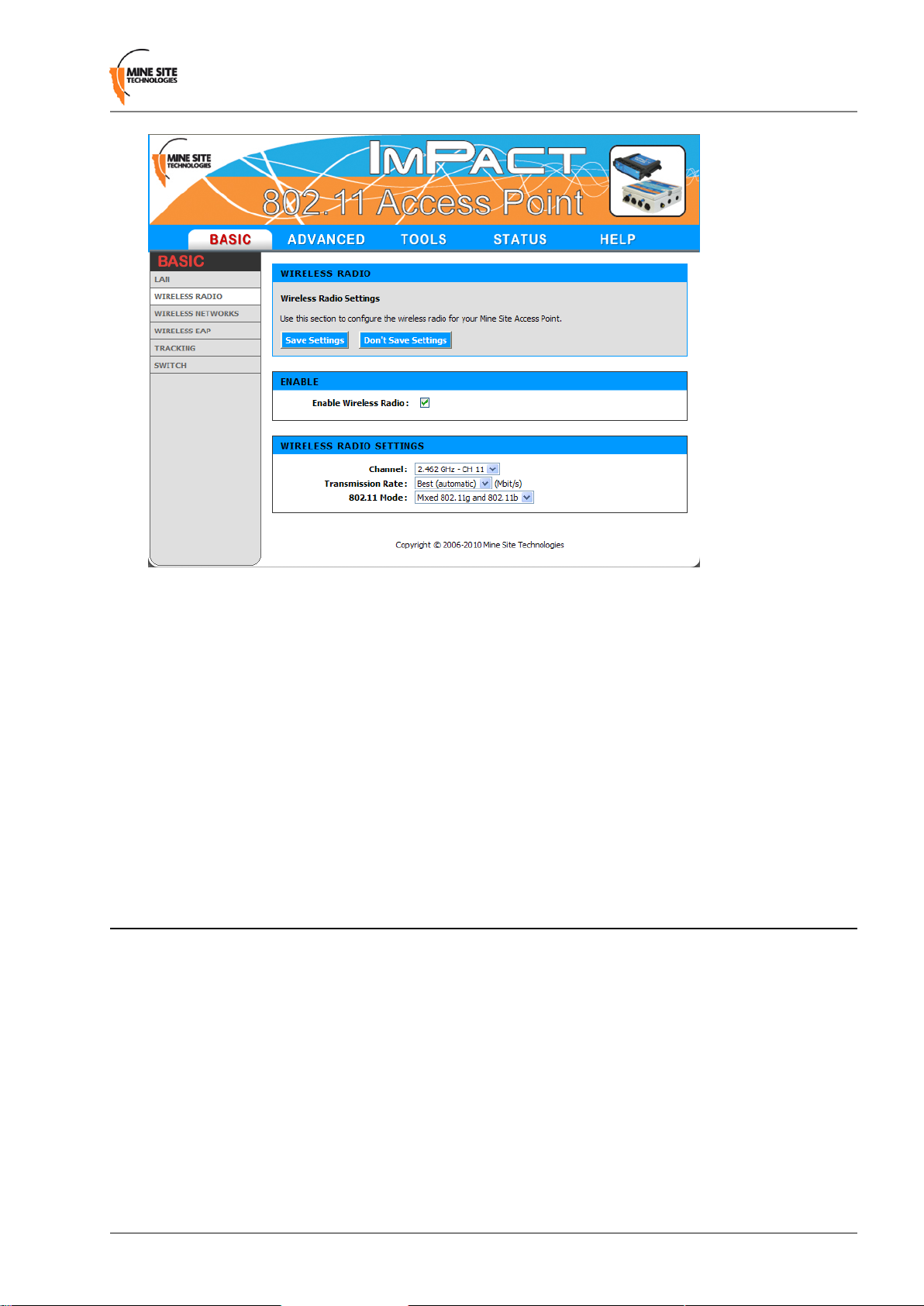
5.3.2 Configuring Wireless Radio
The Wireless Radio configuration screen configures wireless radio settings as shown in Figure 22:
Wireless radio configuration screen.
Revision A52Wireless Network Switch User Manual
Page 53

Configuration Using the Web Interface
Figure 22:Wireless radio configuration screen
To configure the wireless radio:
1. Select the Enable Wireless Radio check box to enable wireless.
2. To change wireless radio settings, click on the drop-down boxes in the supplied fields. A description
and recommended settings are shown in the table below.
3. Click Save Settings.
SettingsDescriptionField
Enable Wireless
Radio
Channel
Transmission
Rate
802.11 Mode
radio.
A drop-down box to select the
wireless channel that the WAC will
operate.
Settings to configure how fast data
is transmitted.
A drop-down box to select the
802.11 mode from mixed 802.11g
and 802.11b to 802.11g.
Checkbox enabled.Used to enable or disable the WAC's
It is recommended WACs in proximity of each
other have different wireless channels (for
example, channels 1, 6 and 11). This minimises
signal overlap and the possibility of interference.
Leave the default setting as Best (automatic)
for data transmission at the best possible speed.
If there are 802.11b wireless client devices, leave
the setting at Mixed. Select 802.11g for
improved performance if all wireless client
devices are 802.11g capable.
5.3.3 Configuring Wireless Networks
A WAC can have up to four wireless SSIDs with different security settings. Each can be mapped to
different VLANs. The configuration screen is shown in Figure 23: Wireless Networks configuration
screen.
Wireless Network Switch User Manual53Revision A
Page 54

Configuration Using the Web Interface
Figure 23:Wireless Networks configuration screen
A description of the wireless network parameters are described in the table below.
SettingsDescriptionField
Click on the Enable check box to
enable the wireless network.
Click on the Visible option button
to enable wireless network visibility .
Enter a network name that relates
closely to its function. For example,
"MST-VOICE".
Selecting the wireless security mode
will display configuration options.
Visibility Status
Wireless
Network Name
Enables or disables the wireless network.Enable
Enables or disables visibility of the wireless
network to client devices within range.
The SSID of the wireless network that is used by
client devices.
Four security modes exist:Security Mode
• None: No wireless authentication is required
and traffic is not encrypted.
• WEP: is the original wireless encryption
standard. This is rarely used.
Revision A54Wireless Network Switch User Manual
Page 55

• WPA Personal: provides a higher level of
security and does not use a centralised
authentication server.
• WPA Enterprise: as per WPA Personal but
a RADIUS authentication server is used.
Configuring WEP Security Settings
Configuration Using the Web Interface
SettingsDescriptionField
To configure WEP security settings:
1. Click on the WEP option button.
2. In the WEP Key Length drop-down box, select 64bit or 128bit. 128bit is a more secure encryption
type.
3. Enter the password for the WEP Key number that will be used.
4. Select the Default WEP Key from the drop-down box.
5. Select Authentication from the drop-down box. By default it is set to Open, which is more secure
than Shared.
Configuring WPA Settings
WPA provides a higher level of security. WPA-Personal and WPA-Enterprise are variants of Wi-Fi
Protected Access (WPA). WPA Enterprise requires an external radius server.
To configure WPA settings:
1. Select the WPA mode from the drop-down box.
2. Select the Cipher Type from the drop-down box. By default it is set at AES.
Wireless Network Switch User Manual55Revision A
Page 56

Configuration Using the Web Interface
3. Enter Group Key Update Interval in the supplied field. By default it is 3600 seconds. This is the
amount of time before the group key (used for broadcast and multicast data encryption) is changed.
4. Enter the Pre-Shared K ey in the supplied field (applicable to WPA Personal security mode). The key
must be at least 8 alphanumeric characters in length.
5. Click Save Settings.
5.3.4 Configuring Wireless Extensible Authentication Protocol (EAP)
The Wireless EAP configuration screen is used to configure wireless authentication by a RADIUS server
(as used by WPA Enterprise). The configuration screen is shown in F igure 24: W ir eless EAP configuration.
Figure 24:Wireless EAP configuration
To configure wireless EAP, click on the drop-down boxes in the supplied fields. Click Save Settings to
save settings. A description of the fields and settings are described in the table below.
SettingsDescriptionField
Authentication Timeout
RADIUS server IP Address
RADIUS server Port
RADIUS server Shared Secret
Amount of time in minutes before
a client device is required to
re-authenticate.
server.
Port number used by the access
point to connect to the
authentication server.
Password used by the access point
to access the RADIUS server.
Setting is at 120 minutes by
default.
This is specific to each site.IP address of the authentication
By default the port number is
1812.
Password that matches with the
authentication server.
Revision A56Wireless Network Switch User Manual
Page 57

Configuration Using the Web Interface
SettingsDescriptionField
MAC Address Authentication
Access to the RADIUS server by
confirmation of the client device's
MAC address.
If selected, the user must always
use the same device when
connecting to the wireless
network.
A second RADIUS server can be configured if the primary server is not av ailable or not responding. This
can be configured by clicking on the Advanced button as shown in Figure 25: Second RADIUS server
configuration.
Figure 25: Second RADIUS server configuration
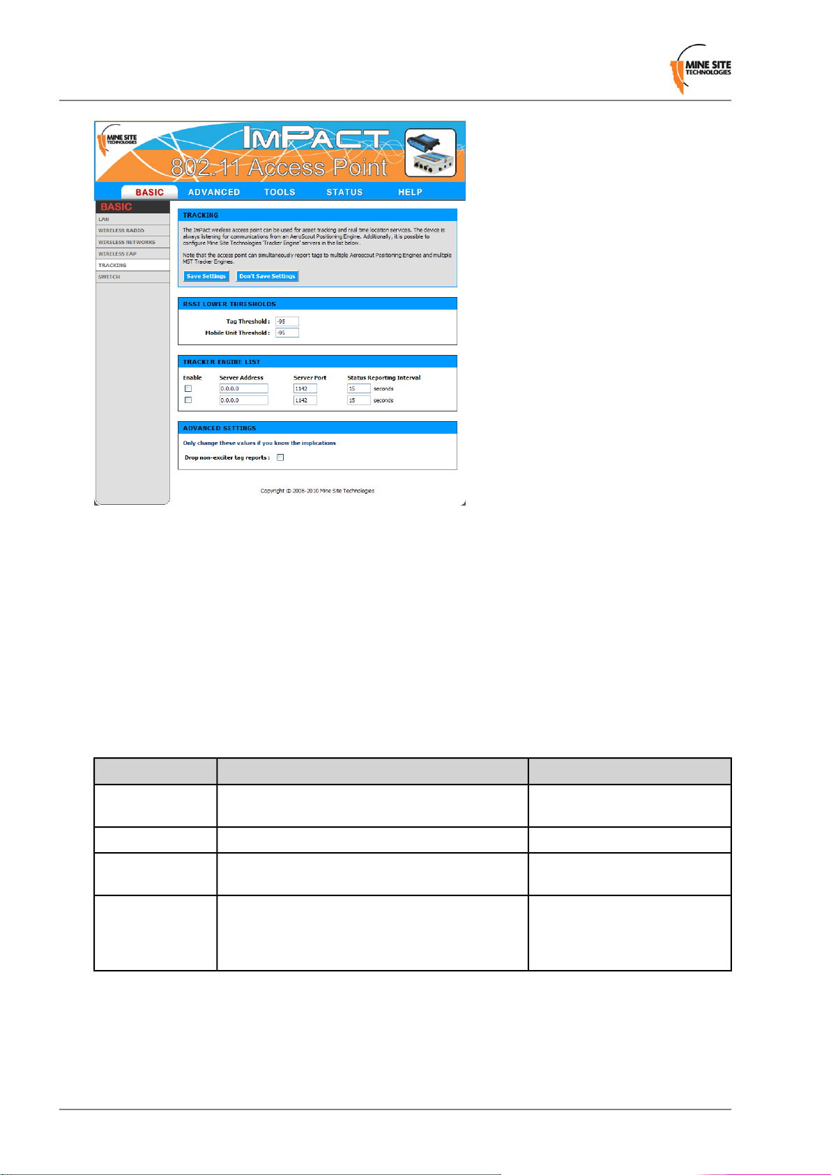
5.3.5 Configuring Asset Tracking and Location Based Services
The T racking configuration screen establishes where AeroScout® tag reports are sent as shown in F igur e
26: Tracking configuration screen. An ImPact network device can communicate with an AeroScout
Positioning Engine and / or a MST Tracker Engine. Configuration of the Access Point is not required
when communicating with an AeroScout® Positioning Engine as the device configuration is performed
via AeroScout® server tools.
®
If the Access Point is sending tag reports to an MST T racker Engine, the T racker Engines IP address must
be entered into each Access Point.
Wireless Network Switch User Manual57Revision A
Page 58
Configuration Using the Web Interface
Figure 26:Tracking configuration screen
There are three sections on the Tracking configuration screen:
RSSI Lower Thresholds
These settings are used to control what location reports are sent to the postioning engine. If a Wi-Fi tag
or mobile unit report is received with an RSSI belo w the relevant threshold, it is not sent to the Positioning
Engine (whether it is an AeroScout® Positioning Engine or MST Tracker Engine).
Tracker Engine List
This section is used to configure the MST Tracker Engine(s) that the access point will send information
to. The av ailable settings are listed below . Note that data can be sent up to 2 MST Tracker Engine instances.
SettingsDescriptionField
Enable
Server Port
Status Reporting
Interval
data.
messages on.
Access Point to the Tracker Engine. These status
reports are used by the Tracker Engine to
determine if the Access Point is up or down.
On or Off.Indicates whether the Track er Engine will be sent
Specific to each site.The IP address of the MST Tracker Engine.Server Address
Default is 1142.The UDP port that the Tracker Engine listens for
Default is 15 seconds.The period that status reports will be sent from the
Advanced Settings
There is a single advanced setting called "Drop non-exciter tag reports". If the check box is enabled, the
Access Point will only send tag reports when the tag is in an AeroScout® exciter field.
This setting applies to tag reports that are sent to AeroScout® Positioning Engines and MST Tracker
Engines.
Revision A58Wireless Network Switch User Manual
Page 59
Configuration Using the Web Interface
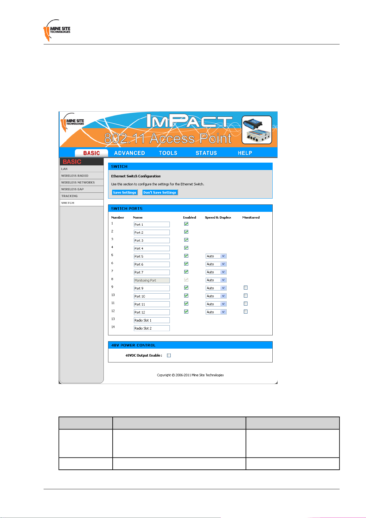
5.3.6 Configuring Ethernet Switch Ports
Accessing the WAC in slot 1 (located on the left side of the WNS) allows the wireless access point to be
configured. It is also used for configuration and management of the switch processors in the network
switch. It enables the ports on the switch and the 48V rail for the Power over Ethernet (PoE) supply to
be configured, as shown in Figure 27: Switch configuration screen.
Figure 27: Switch configuration screen
The Switch ports have the following configuration options:
Name
It is often used to name the device connected to
it. For example, " Level 68 camera".
SettingDescriptionField
Naming is specific to each device.Used to provide a convenient name for the port.
On or Off.Enables or disables the port.Enabled
Wireless Network Switch User Manual59Revision A
Page 60

Configuration Using the Web Interface
SettingDescriptionField
Speed & Duplex
Monitored
Enabling 48v Power Over Ethernet
48VDC PoE supply for ports 9-12 can be enabled by selecting the 48VDC Output Enable check box.
Note: 48VDC PoE capabilities requires “PoE Activation” on each network switch which is an
optional feature. See the Tools > Activation screen to activate the PoE supply feature.
Port 5 to 12 allow the speed and duplex to be
controlled.
to be monitored on port 8 of the device.
Auto is usually the best setting.
However some devices require
Speed & Duplex to be hard coded
due to poor Auto-negotiation
implementations.
On or Off.When enabled, Ports 9 to 12 allow their traffic
5.4 Advanced Tab
The Advanced tab is used to configure the MAC address filters, advanced wireless parameters, VLANs
and WDS.
5.4.1 Enabling the MAC Address Filter
The MAC Address Filter configuration screen specifies MAC addresses to be allowed or denied access
to the network as shown in Figure 28: MAC address filter configuration screen.
Revision A60Wireless Network Switch User Manual
Page 61

Configuration Using the Web Interface
Figure 28: MAC address filter configuration screen
To enable MAC address filtering:
1. Click on the Enable MAC Address Filter check box.
2. Under Filter Settings, select the Mode from the drop-down box to allow or deny listed machines.
3. Click on check boxes to enable to Filter Wireless Clients or Filter Wired Clients.
4. Under Add MAC Address, click on the Enable check box.
5. Enter the MAC address of client device in the MAC Address field.
6. Enter Computer Name in the supplied field and click Save. The MAC address will appear in the
MAC Address List.
Wireless Network Switch User Manual61Revision A
Page 62
Configuration Using the Web Interface
7.
To delete the device from the list, click on the icon.
8.
To edit a device in the list, click on the icon.
9. Click Save Settings.
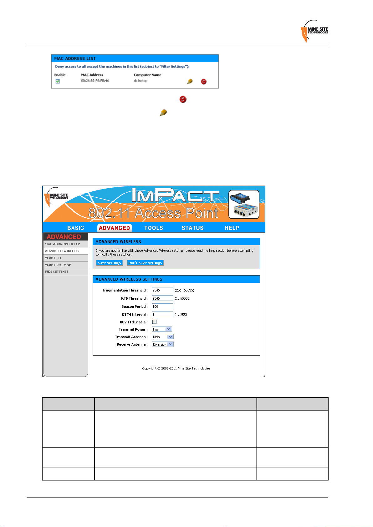
5.4.2 Fine Tuning Wireless Performance
Wireless radio performance can be adjusted on the Advanced Wireless screen as shown in Figure 28:
MAC address filter configuration screen. It is recommended not to modify default settings without
understanding the implications of the changes.
Figure 29: Advanced Wireless configuration screen
Fragmentation
Threshold
RTS threshold
Maximum size a frame size can be sent without
fragmentation.
issues to an RTS packet.
Default SettingsDescriptionField
Default setting is at the
maximum size of 2346
and is recommended for
most environments.
Default setting is 2346.Determines what size data packet the low lev el RF protocol
Default setting is 100ms.The amount of time between beacon transmissions.Beacon Period
Revision A62Wireless Network Switch User Manual
Page 63

Configuration Using the Web Interface
Default SettingsDescriptionField
DTIM interval
802.11d enable
Transmit Power
Transmit Antenna
Receive Antenna
A DTIM is a countdown informing clients of the next
window for listening to broadcast and multicast messages.
Wireless clients detect the beacons and awaken on the
DTIM interval to receive the broadcast and multicast
messages. Valid settings are between 1 and 255.
Wireless specification where configuration occurs at a
MAC layer level to comply with country or district rules.
transmitter.
frames. The options are:
• Main: the MAIN antenna will always be used for
transmission.
• Aux: The AUX antenna will always be used for
transmission.
• Diversity: The radio will determine the best antenna to
use for transmission based on the signal strength of
recently received frames from both antennas.
frames. The options are:
The recommended DTIM
interval by default is 1.
802.11d is not enabled by
default.
High.Used to control the power delivered via the wireless
Main.Defines the antenna to be used for transmission of wireless
Diversity.Defines the antenna to be used for the reception of wireless
• Main: The MAIN antenna will always be used for
reception.
• Aux: The AUX antenna will always be used for
reception.
• Diversity: Both antennas will always be used for
reception and the received frame with the best signal
strength will be used.
Click on the Save Settings button to save advanced wireless settings.
Note: Ensure that the physical connection of antennas is consistent with the transmit and receive
antenna settings. Failure to do so will give poor Wi-Fi performance and reduced tracking accuracy.
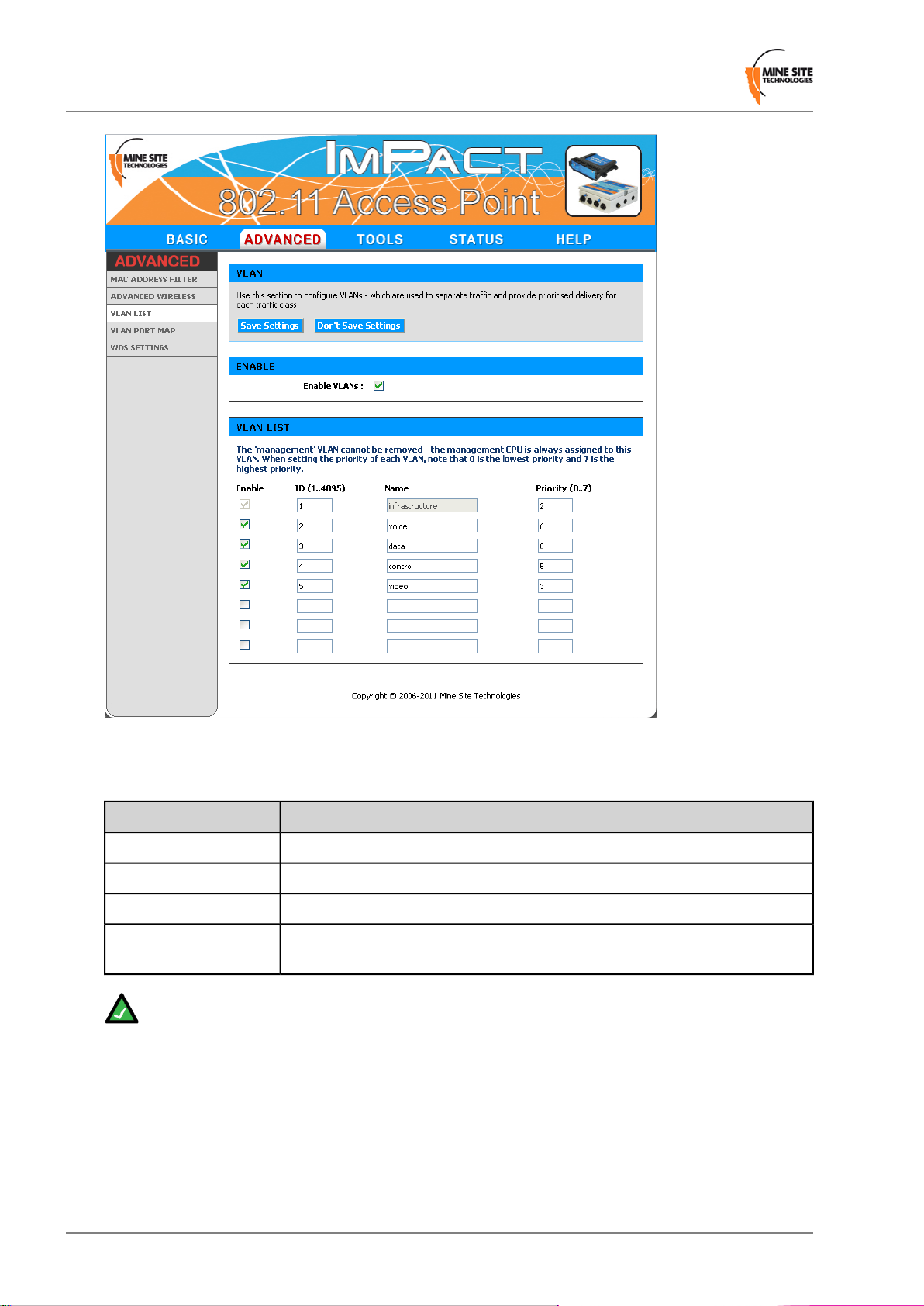
5.4.3 Defining VLANs
VLANs can be defined on the VLAN LIST screen as shown in F igure 30: VLAN list configuration screen.
The VLAN LIST screen displays VLANs and the priorities that will be assigned to each VLAN.
Wireless Network Switch User Manual63Revision A
Page 64
Configuration Using the Web Interface
Figure 30:VLAN list configuration screen
Up to 8 VLANs can be defined with the following parameters described in the table below.
DescriptionField
Check box to enable the VLAN.Enable
VLAN ID number that is tagged in frames sent to trunk ports.ID
VLAN name. It should be named to simplify administration.Name
Priority
Note: The first VLAN (Infrastructure VLAN) cannot be disabled because the management CPU
is always on this VLAN.
By default VLANs are pre-defined with recommended IDs and priorities. This is based on commonly
used applications in mines. Once the VLANs are defined, they can be saved by clicking on the Save
Settings button.
After the VLANs have been defined, they can be assigned to the wireless networks and switch ports
(WNS only) on the VLAN PORT MAP screen.
Priority ranges from 0-7 (7 being the highest priority) that is assigned to frames
on this VLAN.
Revision A64Wireless Network Switch User Manual
Page 65

Configuration Using the Web Interface
5.4.4 Configuring the VLAN Port Map
The VLAN Port Map screen assigns the VLAN(s) to each physical switch port, and each wireless network.
The screen is shown in Figure 31: VLAN Port Map screen.
Physical switch ports can be assigned as Trunk or Access ports. Wireless networks always act as Access
ports onto the relevant VLAN.
Figure 31:VLAN Port Map screen
All ports pass through a single switch processor, but VLAN membership for some ports is configured on
WAC 1 and others on WAC 2 as shown in Figure 32: Logical block diagram of the WNS. All physical
ports can be assigned to be either a trunk port or access port.
Wireless Network Switch User Manual65Revision A
Page 66

Configuration Using the Web Interface
Figure 32: Logical block diagram of the WNS
To configure a port:
1. Set the Mode to be either Trunk or Access (for physical ports).
2. Select the VLAN Membership(s). For an Access port only one VLAN can be selected. For a trunk
port multiple VLANS can be selected.
3. Click Save Settings to save VLAN port map settings.
Note: To configure the VLAN port map properly, it is recommended to understand the principles
of VLANs. For more details on VLANs, see Understanding VLANs on page 43.
5.4.5 Wireless Distribution System (WDS) settings
The Wireless Distribution System (WDS) feature allows wireless interconnection of ImPact network
devices. Up to six devices can be configured.
Revision A66Wireless Network Switch User Manual
Page 67

Configuration Using the Web Interface
To configure WDS settings:
1. Click in the WDS Enable check box.
2. Under WDS Security section, enter the wireless network name (SSID).
3. Select the Security Mode and enter the authentication details.
4. Under WDS Peers, enter the MAC address of the network devices that the device will use WDS to
connect to.
5. Click Save Settings.
Note: WDS links always operate as trunk ports with all VLANs passing across the trunk.
5.5 Tools Tab
The Tools tab is used to configure password access, saving and restoring device configuration, firmware
upgrades and activation of the PoE supply feature in the ImPact network device.
Wireless Network Switch User Manual67Revision A
Page 68
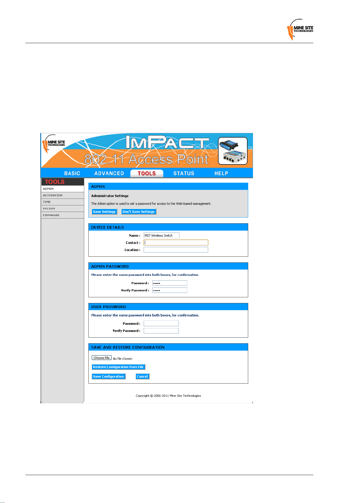
Configuration Using the Web Interface
5.5.1 Configuring Administrator and User Settings
The network device details, administrator and user login can be configured on the Admin configuration
screen as shown in F igur e 33: Admin configur ation scr een. These details are used by the Simple Network
Management Protocol (SNMP) agent.
To enter device details:
1. Enter the device Name, Contact and Location in the supplied fields.
2. Click Save Settings.
Figure 33: Admin configuration screen
The administrator and user password are used to restrict access to the web browser management tool. It
is recommended to create new password for both administrator and user.
To create passwords:
Revision A68Wireless Network Switch User Manual
Page 69

Configuration Using the Web Interface
1. Under ADMIN PASSWORD, enter the administrator password in the Password and the Verify
Password fields. Administrators have full access to the web browser interface.
2. Under USER P ASSWORD, enter the user password in the Password and the Verify Password fields.
Users have read-only access to the web browser interface.
3. Click Save Settings.
5.5.2 Saving and Restoring Configuration Settings
The Admin configuration screen allows network switch settings to be saved as a .gws file. Saved
configuration files can be used to restore settings to the device.
To save network switch settings as a configuration file:
1. Click Save Configuration. A File Download dialog box is displayed.
2. Click on Save. Select a folder to save the configuration file and click Save.
To restore the configuration of a device:
1. Click Choose File and locate the previously saved .gws configuration file. The Choose File to Upload
window will open.
Wireless Network Switch User Manual69Revision A
Page 70
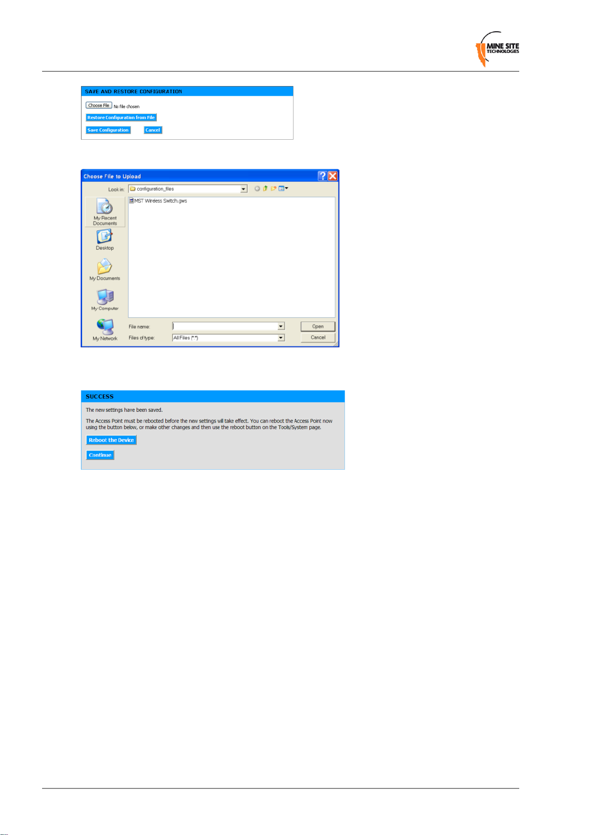
Configuration Using the Web Interface
2. Select the file and click Open.
3. Click Restore Configuration from File. The de vice will upload the configuration file. The SUCCESS
screen is displayed.
4. Click Reboot the Device to reboot or click Continue to return to the previous configuration screen.
Rebooting the device will end the current configuration session.
5.5.3 Activating Power Over Ethernet
The Activation configuration screen is used to enable the PoE supply on a WNS as shown in Figure 34:
P oE activation screen. PoE is an optional extra and an activation code will be issued (please consult your
MST engineer for details). Enter the activation code, click Sa ve Settings and reboot to enable PoE supply .
Revision A70Wireless Network Switch User Manual
Page 71

Configuration Using the Web Interface
Figure 34: PoE activation screen
5.5.4 Setting the Time
The Time configuration screen shown in Figure 35: T ime configur ation screen is used to define regional
time settings on the device.
Wireless Network Switch User Manual71Revision A
Page 72

Configuration Using the Web Interface
Figure 35:Time configuration screen
To set the time:
1. Select the appropriate time zone from the Time Zone drop-down box.
2. Click Enable Daylight Saving check box if the selected region has daylight saving. Daylight saving
options will be displayed.
3. Select the Daylight Saving Offset in the drop-down box.
4. Select the region's DST Start date and DST End date.
5. Click Save Settings.
Automatic Time Configuration
Time on the device can be synchronised to a Network Time Protocol (NTP) server. The NTP lookup is
performed by the switch's management CPU, which resides on the Infrastructure VLAN.
Revision A72Wireless Network Switch User Manual
Page 73

Configuration Using the Web Interface
To enable a NTP server:
1. Select Enable NTP Server check box.
2. Enter the NTP server name (the IP address or a host name), or select a NTP server from the drop-down
box.
3. Click Save Settings.
Note: If the network device loses power, network time will not be maintained. If NTP is enabled,
the network switch will synchronise the time shortly after power up.
Note: If a host name is entered, DNS settings must be configured and the device must be able to
contact the DNS server.
Manual Time Configuration
Time on a device can be set manually if there is no access to a Network Time Protocol (NTP) server.
To set the time manually:
1. Select the time and date from the drop-down boxes.
2. Alternatively , click Copy Your Computer's T ime Settings button to copy the time from the connected
computer.
3. Click Save Settings.
5.5.5 Rebooting or Restoring the Network Device
The System configuration screen enables the device to be rebooted or restored to the factory default
settings as shown in Figure 36: System configuration screen.
Wireless Network Switch User Manual73Revision A
Page 74
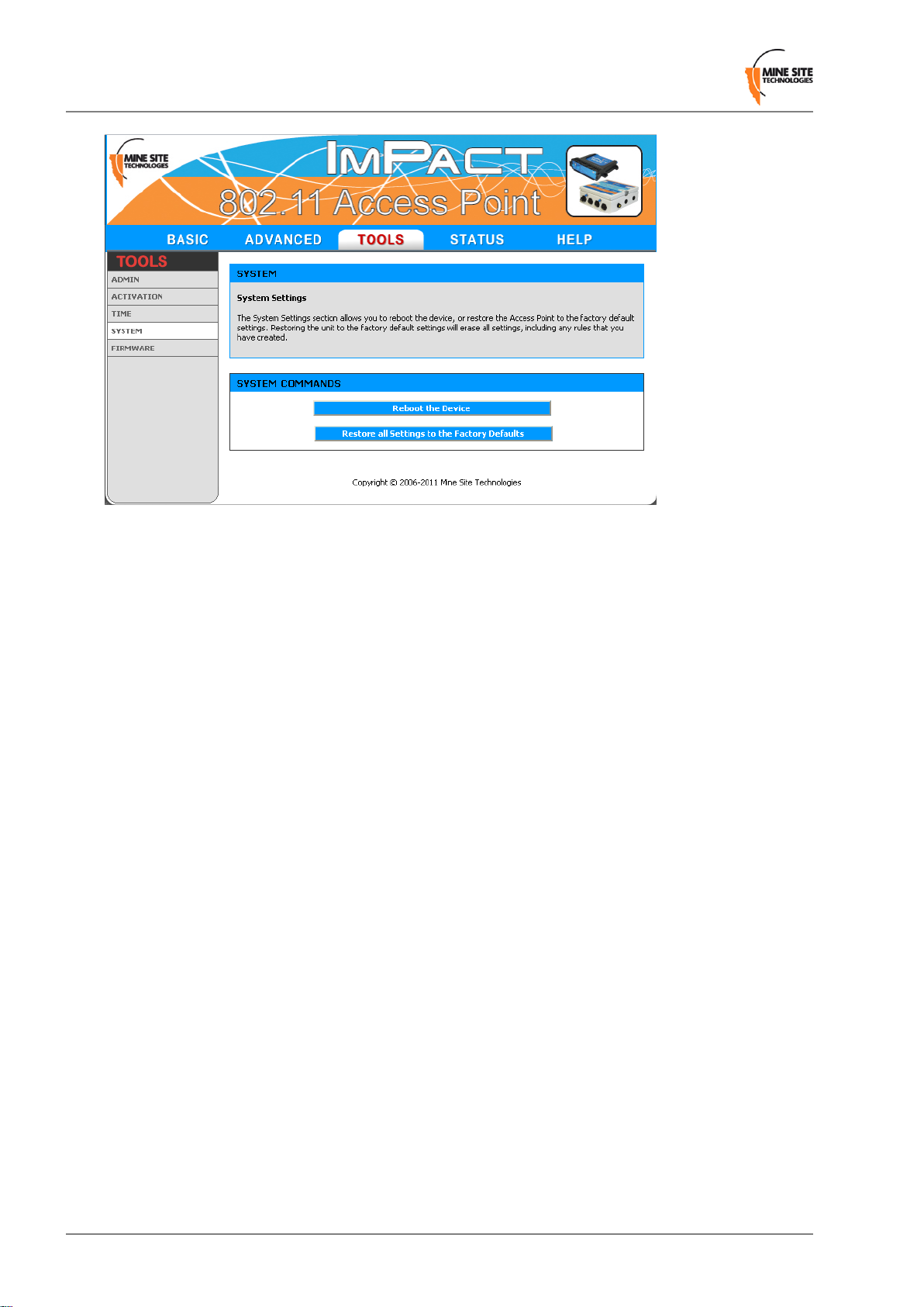
Configuration Using the Web Interface
Figure 36: System configuration screen
Click Reboot the Device to reboot the WNS. Any unsaved settings on the device will be lost and the
connection will terminate.
Click Restore all Settings to the Factory Defaults to restore the WNS to default settings. All current
settings will be erased.
5.5.6 Upgrading Firmware
Device Firmware can be upgraded from the Firmware upgrade screen as shown in Figure 37: F irmware
upgrade screen. The firmware is a binary (.bin) file format.
Revision A74Wireless Network Switch User Manual
Page 75

Configuration Using the Web Interface
Figure 37: Firmware upgrade screen
Important: Firmware upgrades may reset the network device to default factory settings (please
refer to the firmware release notes to determine if this will occur). It is highly recommended to save
configuration settings before updating firmware. For more information, see Saving and Restoring
Configuration Settings
It is recommended that a client device (PC or laptop) has a wired connection to the network device to
upgrade the firmware. Please contact your MST System Engineer for firmware files.
To upgrade the firmware:
1. Click Browse. The Choose File to Upload dialog box will open.
Wireless Network Switch User Manual75Revision A
Page 76

Configuration Using the Web Interface
2. Select the binary (.bin) firmware file and click Open.
3. Click Upload. The firmware will upload to the device.
4. When the firmware has been successfully uploaded, the UPLOAD SUCCEEDED screen will appear .
The network switch will reboot after 60 seconds.
5. Previous configuration settings can be restored to the network switch via the TOOLS > ADMIN
configuration screen.
5.6 Status Tab
The Status tab displays device information, wireless clients, system logs, network traffic statistics and
the most recent Wi-Fi tag reads.
5.6.1 Obtaining Device Information
The Device Info status screen as shown in Figure 38: Device Info Status screen displays system time,
firmware version, LAN and wireless LAN summary information.
Revision A76Wireless Network Switch User Manual
Page 77
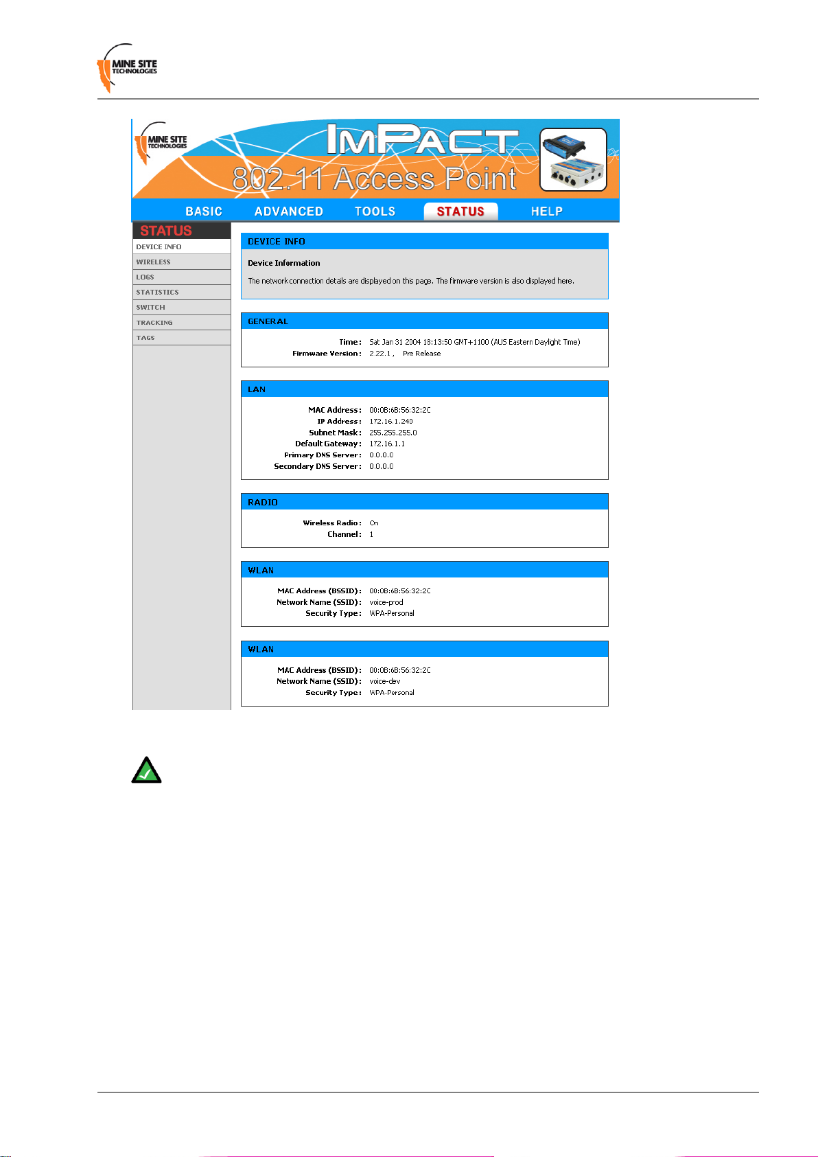
Configuration Using the Web Interface
Figure 38: Device Info Status screen
Note: Changes in status display are dependent on the web browser . Some web browsers may report
an error when obtaining WLAN status, or require to refresh the web browser screen.
5.6.2 Wireless Client Information
The Wireless status screen displays current information about wireless clients connected to the access
point.
Wireless Network Switch User Manual77Revision A
Page 78
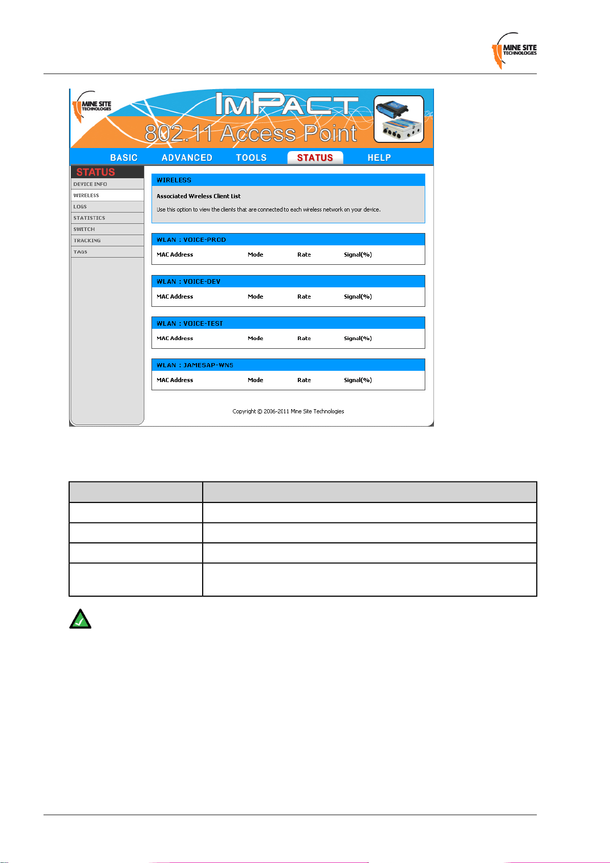
Configuration Using the Web Interface
Figure 39:Wireless status screen
A description of each field is listed in the following table.
DescriptionField
The address of the client device.MAC Address
Indicates if the client device is in 802.11b or 802.11g mode.Mode
The data rate for the connection in Mbps.Rate
Signal
Note: The wireless client device list groups devices by the wireless SSID.
The percentage signal strength of the client device, as received by the
access point.
5.6.3 Viewing System Logs
The Logs screen displays the device logs. It is possible to filter by the type of logged ev ents and the ev ent
level.
Revision A78Wireless Network Switch User Manual
Page 79
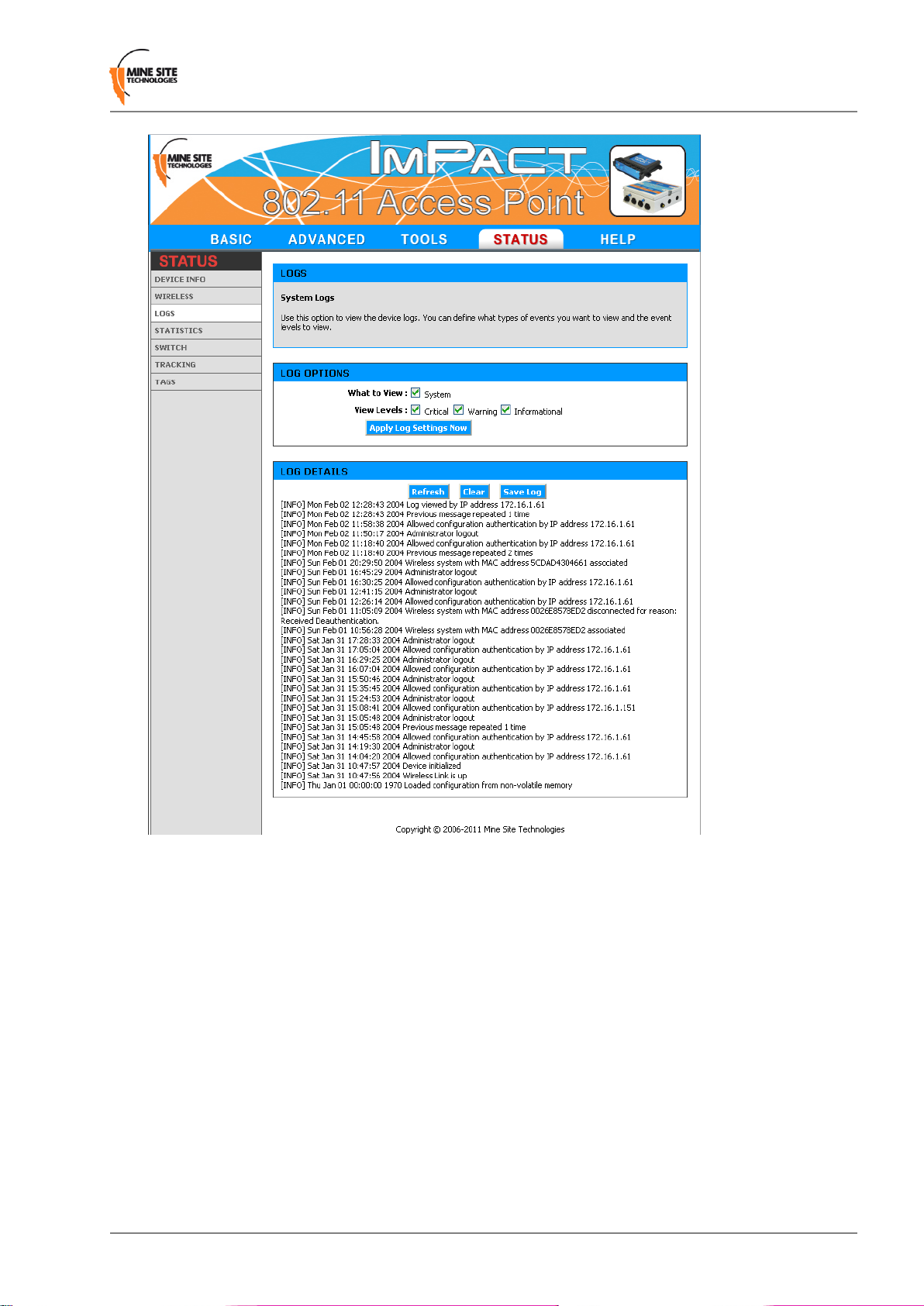
Configuration Using the Web Interface
Figure 40: Logs status screen
To define LOG OPTIONS:
1. In the What to View fields, select the System check box.
2. In the View Levels field, select the check boxes on the reporting levels required.
3. Click Apply Log Settings Now.
To view LOG DETAILS:
1. Click Refresh to update the list.
2. Click Clear to clear the list. A confirmation message box is displayed.
3. Click OK to continue.
4. Click Save Log to save the log as a text file. A log of the clear action is recorded. Any changes made
to the log characteristics are also recorded in the log.
Wireless Network Switch User Manual79Revision A
Page 80

Configuration Using the Web Interface
5.6.4 Viewing Network Traffic Statistics
The Statistics status screen provides network traffic statistics for the WAC's LAN interface and each of
the wireless SSIDs.
Figure 41: Statistics status screen
To view statistics:
1. Click Refresh Statistics to update the statistics.
2. Click Clear Statistics to clear displayed statistics. A reset confirmation dialog box is displayed.
3. Click OK.
A description of the parameters are listed in the following table.
DescriptionStatistic
The number of frames sent.Sent
The number of frames received.Received
TX Packets Dropped
RX Packets Dropped
The number of frames dropped while being sent, due to errors, collisions,
or network switch resource limitation.
The number of frames dropped while being received, due to errors,
collisions, or network switch resource limitation.
The number of frames dropped due to Ethernet collisions.Collisions
The number of transmission failures that caused the loss of a packet.Errors
Revision A80Wireless Network Switch User Manual
Page 81

Configuration Using the Web Interface
5.6.5 Viewing Ethernet Switch Information
The Switch status screen displays general switch information as shown in F igure 42: Switc h status screen.
Switch information can only be accessed from the WAC in slot 1 of the WNS. It displays the following
parameters:
• The temperature inside the switch processor
• The voltage of the supply rail
• The voltage of the PoE rail
• The vendor and part number for each of the SFP modules
• The link, speed, duplex and PoE power status for each switch port.
Figure 42: Switch status screen
Wireless Network Switch User Manual81Revision A
Page 82

Configuration Using the Web Interface
5.6.6 Viewing Tracking Information
The Tracking status screen displays the status of the tracking servers that are registered to the network
device as shown in Figure 43: Tracking status screen.
Figure 43:Tracking status screen
5.6.7 Viewing Recent Tag Reports
The T ags status screen displays the last ten AeroScout tag reads when asset tracking and location services
are enabled.
Revision A82Wireless Network Switch User Manual
Page 83

Configuration Using the Web Interface
Figure 44:Tags status screen
A description of the tag status parameters are listed in the following table.
DescriptionField
MAC address of the tag being read.MAC Address
RSSI
This screen assists to verify the following:
• The device is detecting AeroScout® tags.
• Tag reports are generated for a particular tag by viewing sequence number.
• Received RF signal strength.
Received Signal Strength Indicator (RSSI) is a measurement of the quality
of the received radio signal.
The sequence number of the tag transmission.Sequence
Wireless Network Switch User Manual83Revision A
Page 84

Page 85

Chapter
6
Centralised Configuration Management
Topics:
• Overview
• Site Configuration files
• Editing Site Configuration Files
• Device Configuration Files
• Editing Device Configuration
Files
• Applying Configuration Files
Centralised configuration management is another configuration method
for ImPact network devices. It uses Trivial File Transfer Protocol
(TFTP) where devices read and apply configuration files from a TFTP
server. It is a faster way to configure a large number of network
switches, reducing the potential for human error.
Wireless Network Switch User Manual85Revision A
Page 86

Centralised Configuration Management
6.1 Overview
Centralised configuration management involves the following steps:
1. Configure a TFTP server on the network.
2. Define a site configuration file which contain global settings to all network devices on the site.
3. Define device configuration files which contain specific settings for each device, which o verride global
settings.
4. Applying the configuration files to each device and rebooting.
Network devices read and apply the configuration files from the TFTP server as shown in Figure 45:
Centralised configuration management .
Figure 45: Centralised configuration management
6.2 Site Configuration files
Site configuration files contain common settings for all devices in a network. The site configuration file
has the naming convention ap_site_settings.conf. This file is retrieved by devices using TFTP.
Revision A86Wireless Network Switch User Manual
Page 87

Centralised Configuration Management
Note: The same site configuration file can be used to configure WNS units and WAPs in a network.
When the site configuration file is applied to WAPs, all switch port settings are ignored by the
WAP.
6.3 Editing Site Configuration Files
The site configuration file can be opened on a PC and edited using a text editor. Parameters are changed
by modifying the text and saving the file. A description of the editable parameters are covered in the
following sections.
To edit a site configuration file:
1. Open a text file editor on your PC.
2. Locate and open the site configuration file ap_site_settings.conf. This is usually stored in the file
directory folder of the TFTP server.
3. Edit the parameters as required.
4. Save the site configuration file in the directory folder of the TFTP server.
6.3.1 Network
The network section of the configuration file defines common LAN settings to all devices on a network
as shown below.
# Mine Site Technologies Wireless Network Switch / Wireless Access Point Site
Config File
# Network
# =======
network.netmask=255.255.255.0
network.gateway=10.11.12.1
network.dns.primary=10.11.12.1
network.dns.secondary=
network.local_domain_name='minesite.com.au'
A description of the network parameters are listed in the following table.
DescriptionText field
The subnet mask for the network.network.netmask
The IP address of the default gateway.network.gateway
The DNS server to be used when looking up host names.network.dns.primary
network.dns.secondary
The backup DNS server to be used when looking up host
names.
The domain name of the local network.network.local_domain_name
Wireless Network Switch User Manual87Revision A
Page 88

Centralised Configuration Management
6.3.2 System
Network names, contact details and passwords can be edited in the system section of the configuration
file as shown below.
# System
# ======
system.contact='Joe Citizen'
system.location='Mine Location-14'
system.admin_password='admin'
system.user_password='user'
A description of the system parameters are listed in the following table.
DescriptionText field
Contact name for the network devices.system.contact
Location of the network devices.system.location
Administrator password. The default password is "admin".system.admin_password
User password. The default password is "user".system.user_password
6.3.3 Setting the Time
The Time section shown below defines regional time settings for the network switch.
# Time
# ====
time.timezone.index=66
time.timezone.offset=36000
time.daylight_saving.enabled=1
time.daylight_saving.offset=3600
time.daylight_saving.start.month=10
time.daylight_saving.start.week_of_month=1
time.daylight_saving.start.day_of_week=1
time.daylight_saving.start.hour=2
time.daylight_saving.finish.month=4
time.daylight_saving.finish.week_of_month=1
time.daylight_saving.finish.day_of_week=1
time.daylight_saving.finish.hour=2
time.ntp.enabled=1
time.ntp.server='time.iinet.net.au'
The editable parameters are described in the following table.
DescriptionField
time.timezone.index
time.timezone.offset
time.daylight_saving.enabled
The index representing the timezone the device is in. Refer to
Timezone Indices and Of fsets on page 111 for values and countries.
Timezone offset from Greenwich Mean Time (GMT) represented
in seconds. Refer to Timezone Indices and Offsets on page 111
for offset values.
Daylight saving can be enabled by entering 1 or disabled by
entering 0.
Time offset value in seconds when daylight savings is enabled.time.daylight_saving.offset
Revision A88Wireless Network Switch User Manual
Page 89

Centralised Configuration Management
DescriptionField
time.daylight_saving.start.month
time.daylight_saving.start.week_of_month
time.daylight_saving.start.day_of_week
time.daylight_saving.start.hour
time.daylight_saving.finish.month
time.daylight_saving.finish.week_of_month
time.daylight_saving.finish.day_of_week
time.daylight_saving.finish.hour
time.ntp.enabled
The month when daylight saving starts. Accepted values are from
1 to 12.
W eek of the month when daylight savings starts. Accepted v alues
are from 1 to 5.
Day of the week when daylight saving starts. Accepted values are
from 1 to 7 where 1=Sunday.
Hour of the day when daylight saving will start. Accepted values
are from 0 - 23.
Month when daylight saving will end. Accepted values are from
1 - 12.
Week of the month when daylight saving will finish. Accepted
values are from 1 - 5.
Day of the week when daylight saving will finish. Accepted values
are from 1 - 7; where 1=Sunday.
Hour of the day when daylight saving will finish. Accepted values
are from 0 - 23.
Enables the device to synchronise time with a Network Time
Protocol (NTP) server . Enter 1 to enable, 0 to disable. The network
switch requires access to the DNS server and the NTP server.
time.ntp.server
Domain name of Network Time Protocol (NTP) server. For
example time.windows.net.
6.3.4 Enabling Power Over Ethernet
Power Over Ethernet enables the 48VDC PoE supply feature. In the switch.poe.enabled field type 1
to enable or 0 to disable.
Note: 48VDC PoE capabilities requires “PoE Activation” on each network switch which is an
optional feature. PoE activation is enabled with an unique activation code entered in the device
configuration file. Please consult your MST System Engineer for more details.
6.3.5 Setting up Asset Tracking and Location Servers
The Tracking section shown below configures asset tracking and location servers, consisting of
AeroScout® Positioning Engines or MST Tracker Engines. This is where AeroScout® tag and Wi-Fi
client device information is sent. Configuration is not required when communicating with an AeroScout
positioning engine.
# Tracking
# ========
®
tracking.tag_rssi_threshold=-95
tracking.mu_rssi_threshold=-95
tracking.tracker_engine.1.enabled=0
tracking.tracker_engine.1.server_address=10.11.12.158
Wireless Network Switch User Manual89Revision A
Page 90

Centralised Configuration Management
tracking.tracker_engine.1.server_port=1142
tracking.tracker_engine.1.status_reporting_interval=10
tracking.tracker_engine.2.enabled=0
tracking.tracker_engine.2.server_address=10.11.12.159
tracking.tracker_engine.2.server_port=1142
tracking.tracker_engine.2.status_reporting_interval=3
A device can be configured to communicate with up to two MST Tracker Engines. A description of the
setup parameters are listed in the table below.
DescriptionField
tracking.tag_rssi_threshold
By default it is set at -95. Only tag reports higher than this signal strength
threshold will be sent to the positioning engines.
tracking.mu_rssi_threshold
By default it is set at -95. The default v alue should not be changed without
understanding the implications. Only W i-Fi client frames higher than this
signal strength threshold will be sent to the positioning engines.
enabled
The reporting to MST Tracking Engine can be enabled by entering 1 to
enable or 0 to disable.
The IP address of the MST Tracking Engine.server_address
UDP port to be used by messages sent to the MST Tracker Engine.server_port
status_reporting_interval
The period between status reports being sent to the MST Track er Engine.
These status reports are used to determine Access point availability.
6.3.6 Switch Configuration
The Switch Configuration section is used to control switch ports and assign VLANs.
# Switch Configuration
# ====================
switch.port.1.enabled=0
switch.port.1.name=Backbone 1
switch.port.1.vlan_mode=1
switch.port.1.vlan_membership=1
switch.port.2.enabled=0
switch.port.2.name='Backbone 2'
switch.port.2.vlan_mode=2
switch.port.2.vlan_membership=255
switch.port.3.enabled=0
switch.port.3.name='Backbone 3'
switch.port.3.vlan_mode=2
switch.port.3.vlan_membership=255
switch.port.4.enabled=0
switch.port.4.name='Backbone 4'
switch.port.4.vlan_mode=2
switch.port.4.vlan_membership=255
switch.port.5.enabled=1
switch.port.5.name='Internal'
switch.port.5.speed=7
switch.port.5.vlan_mode=1
switch.port.5.vlan_membership=1
Revision A90Wireless Network Switch User Manual
Page 91

switch.port.6.enabled=1
switch.port.6.name='Internal'
switch.port.6.speed=7
switch.port.6.vlan_mode=1
switch.port.6.vlan_membership=1
switch.port.7.enabled=1
switch.port.7.name='Internal'
switch.port.7.speed=7
switch.port.7.vlan_mode=1
switch.port.7.vlan_membership=1
# Switch Port 8 settings cannot be changed
switch.port.9.enabled=1
switch.port.9.name='Network Uplink'
switch.port.9.speed=7
switch.port.9.vlan_mode=1
switch.port.9.vlan_membership=2
switch.port.10.enabled=1
switch.port.10.name='Trunk Uplink'
switch.port.10.speed=7
switch.port.10.vlan_mode=2
switch.port.10.vlan_membership=7
Centralised Configuration Management
switch.port.11.enabled=1
switch.port.11.name='WAP52 Connection'
switch.port.11.speed=7
switch.port.11.vlan_mode=2
switch.port.11.vlan_membership=7
switch.port.12.enabled=1
switch.port.12.name='Dongle'
switch.port.12.speed=7
switch.port.12.vlan_mode=1
switch.port.12.vlan_membership=1
# Switch Port 13 cannot have its configuration changed
switch.port.14.enabled=1
# Switch Port 14 cannot have its name changed
switch.port.14.vlan_mode=2
switch.port.14.vlan_membership=7
# Power over Ethernet
# ------------------switch.poe.enabled=1
For more information on understanding VLANs, trunk and access ports, See Chapter 4 "Understanding
VLANs".
6.3.7 VLAN Configuration
The VLANs section defines VLANs for the de vices as shown belo w . For large networks it is recommended
that VLAN settings are applied to all network devices consistently by using centralised configuration
management.
# VLAN Configuration
# ==================
vlan.enabled=1
Wireless Network Switch User Manual91Revision A
Page 92

Centralised Configuration Management
# VLAN 1 cannot be disabled or have its name changed
vlan.entry.1.priority=3
vlan.entry.1.id=1
vlan.entry.2.enabled=1
vlan.entry.2.id=3
vlan.entry.2.priority=1
vlan.entry.2.name='data'
vlan.entry.3.enabled=1
vlan.entry.3.id=2
vlan.entry.3.priority=6
vlan.entry.3.name='voice '
vlan.entry.4.enabled=0
vlan.entry.4.id=5
vlan.entry.4.priority=5
vlan.entry.4.name='video'
vlan.entry.5.enabled=0
vlan.entry.5.id=6
vlan.entry.5.priority=0
vlan.entry.5.name='telemetry'
vlan.entry.6.enabled=0
vlan.entry.6.id=7
vlan.entry.6.priority=0
vlan.entry.6.name=''
vlan.entry.7.enabled=0
vlan.entry.7.id=8
vlan.entry.7.priority=0
vlan.entry.7.name=''
vlan.entry.8.enabled=0
vlan.entry.8.id=513
vlan.entry.8.priority=8
vlan.entry.8.name='garbage'
Up to 8 VLANs can be defined. Each entry.x in the VLAN section represents a VLAN. By default, the
site configuration file has some VLANs predefined based on commonly used applications. VLAN
parameters are described in the table below.
DescriptionField
Sets whether VLANs are enabled on the switch.vlan.enabled
vlan.entry.x.enabled
Enables VLAN x. Typing 1 will enable the VLAN, 0 will disable
the VLAN.
vlan.entry.x.id
The VLAN ID that will be tagged to frames sent to trunk ports from
VLAN x.
vlan.entry.x.priority
Priority from 0-7 (with 7 being the highest) that is assigned to frames
on VLAN x.
The administrative name for VLAN x.vlan.entry.x.name
Note: The Infrastructure VLAN cannot be edited or disabled because the management CPU is on
this VLAN.
Revision A92Wireless Network Switch User Manual
Page 93

Centralised Configuration Management
For more information on understanding VLANs, refer to Under standing VLANs on page 43 in the WNS
User Manual.
6.3.8 Wireless EAP Configuration
The Wireless EAP section is used to configure the RADIUS server as shown below. This is applicable
for wireless networks configured with WPA Enterprise security mode.
Wireless EAP Configuration
==========================
wireless.eap.reauth_time=120 # 1 - 65535
wireless.eap.primary.auth_mac=1
wireless.eap.primary.server_address=192.168.1.220
wireless.eap.primary.server_port=1815
wireless.eap.primary.shared_secret='secret1'
wireless.eap.secondary.auth_mac=0
wireless.eap.secondary.server_address=192.168.1.221
wireless.eap.secondary.server_port=1816
wireless.eap.secondary.shared_secret='secret2'
A primary and secondary (backup) RADIUS server can be setup and configured. A description of the
editable parameters are shown in the following table.
SettingsDescriptionField
reauth_time
Setting is at 120 minutes by default.Amount of time in minutes before a client
device is required to re-authenticate.
auth_mac
Access to the RADIUS server by confirmation
of the MAC address of the client device.
Authentication is enabled by typing
1 or disabled by typing 0.
n/a.The IP address of the authentication server.server_address
server_port
By default the port number is 1812.The port number used to connect to the
authentication server.
shared_secret
Password used by the Access point to access
the RADIUS server.
Password that matches with the
authentication server.
6.3.9 Wireless Network Configuration
Each WAC in a device can have up to four wireless SSIDs, each with different security settings and
different mappings to VLANs.
# Wireless Network Configuration
# ==============================
# Wireless Network 1
# -----------------wireless.network.1.enabled=1
wireless.network.1.ssid='MST-VOICE'
wireless.network.1.invisibility=0
wireless.network.1.dtim_interval=1
wireless.network.1.vlan_membership=4
wireless.network.1.security_mode=2
# Network 1, WEP Settings
wireless.network.1.wep.auth=1
wireless.network.1.wep.keylen=0
Wireless Network Switch User Manual93Revision A
Page 94

Centralised Configuration Management
wireless.network.1.wep.use_key=1
wireless.network.1.wep.key.1='mine1'
wireless.network.1.wep.key.2='1234567890'
wireless.network.1.wep.key.3='1234567890'
wireless.network.1.wep.key.4='1234567890'
# Network , WPA Settings
wireless.network.1.wpa.mode=1
wireless.network.1.wpa.cipher=1
wireless.network.1.wpa.rekey_time=3600
wireless.network.1.wpa.psk='password'
# Wireless Network 2
# -----------------wireless.network.2.enabled=1
wireless.network.2.ssid='MST-DATA'
wireless.network.2.invisibility=0
wireless.network.2.dtim_interval=1
wireless.network.2.vlan_membership=2
wireless.network.2.security_mode=3
# Network 1, WEP Settings
wireless.network.2.wep.auth=1
wireless.network.2.wep.keylen=0
wireless.network.2.wep.use_key=2
wireless.network.2.wep.key.1='1234567890'
wireless.network.2.wep.key.2='123456789G'
wireless.network.2.wep.key.3='123456789a'
wireless.network.2.wep.key.4='12345678fd'
# Network , WPA Settings
wireless.network.2.wpa.mode=3
wireless.network.2.wpa.cipher=2
wireless.network.2.wpa.rekey_time=3600
wireless.network.2.wpa.psk='mineract'
# Wireless Network 3
# -----------------wireless.network.3.enabled=1
wireless.network.3.ssid='MST-INFRA'
wireless.network.3.invisibility=0
wireless.network.3.dtim_interval=3
wireless.network.3.vlan_membership=1
wireless.network.3.security_mode=3
# Network 1, WEP Settings
wireless.network.3.wep.auth=1
wireless.network.3.wep.keylen=1
wireless.network.3.wep.use_key=3
wireless.network.3.wep.key.1='12345678902551234567890255'
wireless.network.3.wep.key.2='1234567890255123456789c255'
wireless.network.3.wep.key.3='1234567890255123456789h255'
wireless.network.3.wep.key.4='12345678902551234567890255'
# Network , WPA Settings
wireless.network.3.wpa.mode=3
wireless.network.3.wpa.cipher=2
wireless.network.3.wpa.rekey_time=3600
wireless.network.3.wpa.psk='minesite'
# Wireless Network 4
# -----------------wireless.network.4.enabled=0
Revision A94Wireless Network Switch User Manual
Page 95

Centralised Configuration Management
wireless.network.4.ssid='data'
wireless.network.4.invisibility=1
wireless.network.4.dtim_interval=3
wireless.network.4.vlan_membership=1
wireless.network.4.security_mode=2
# Wireless Network 4, WEP Settings
wireless.network.4.wep.auth=1
wireless.network.4.wep.keylen=0
wireless.network.4.wep.use_key=4
wireless.network.4.wep.key.1='12345678902551234567890255'
wireless.network.4.wep.key.2='12345678902551234567890255'
wireless.network.4.wep.key.3='12345678902551234567890255'
wireless.network.4.wep.key.4='12345678902551234567890255'
# Wireless Network 4, WPA Settings
wireless.network.4.wpa.mode=4
wireless.network.4.wpa.cipher=4
wireless.network.4.wpa.rekey_time=3600
wireless.network.4.wpa.psk='password'
The wireless network parameters are described in the following table.
ssid
invisibility
dtim_interval
vlan_membership
The name of the wireless network visible to client
devices.
Enables or disables visibility of the wireless
network to anyone within range.
A DTIM is a countdown informing clients of the
next window for listening to broadcast and
multicast messages. Wireless clients detect the
beacons and awaken on the DTIM interval to
receive the broadcast and multicast messages.
network. VLANs are defined in the VLAN
configuration section of the site configuration file.
Three selectable wireless security modes:security_mode
• WEP is the original wireless encryption
standard.
• WPA provides a higher level of security.
SettingsDescriptionField
Enter 1 to enable or 0 to disable.Enables or disables the wireless network.enabled
Choose a network name that
relates closely to its function. For
example "MST-VOICE".
Click on the Visible option button
to enable wireless network
visibility.
Valid settings are between 1 and
255. The recommended DTIM
interval is 1.
VLAN range from 1-8.The VLAN assigned to devices on the wireless
Security settings include 1 = Open,
2 = WEP, 3 = WPA-Personal, 4 =
WPA-Enterprise
• WPA-Personal does not require an
authentication server.
• WPA-Enterprise requires a RADIUS
authentication server.
Wireless Network Switch User Manual95Revision A
Page 96

Centralised Configuration Management
6.4 Device Configuration Files
Device configuration files contain settings specific to each WAC in the network device. A device
configuration file is created for each WAC. Device configuration files follow the naming convention
ap_MACaddress.conf where MACaddress is the MAC address of the WAC. A device will recognise
and apply the device configuration file based on a comparison of the MAC address in the file name.
Note that any parameter from the site configuration file can override parameters in a de vice configuration
file. However, it is recommended that only the settings that are different be entered into the device
configuration file in order to make maintenance easier.
6.5 Editing Device Configuration Files
A device configuration file configures individual settings for each device as shown below. The device
configuration file can be edited using a text editor such as Wordpad or Notepad. The example below
includes settings that are commonly over-ridden. All other settings are inherited from the global site
configuration file.
# Mine Site Technologies Wireless Network Switch Config File
# System
# ======
#
system.hostname='AP57R2'
system.location="Mine Location 16"
# Network
# =======
#
network.addr=192.168.0.247
# Wireless Radio Configuration
# ============================
#
wireless.radio.channel = 11
# Feature Activation
# ==================
#
#system.activation_code='f085f3f2-6a55f34a-8cacf508-c64e98bd-0c95136f'
The parameters shown in the example device configuration file are described in the following table.
SettingsDescriptionParameterSection
Network switch name.system.hostnameSystem
Each device should have a unique name
identifier.
system.locationSystem
Location name of the
network switch.
It is recommended the location name
is relevant to the physical location of
the device.
network.addrNetwork
IP address of the WAC
in the network switch.
Every WAC will be assigned a unique
IP address.
Revision A96Wireless Network Switch User Manual
Page 97
Centralised Configuration Management
SettingsDescriptionParameterSection
It is recommended WACs in proximity
of each other have assigned channels
Radio
wireless.radio.channelWireless
Wi-Fi channel that the
WAC will operate on.
Configuration 1, 6 and 11. This minimises signal
overlap and interference.
Please consult your MST System
Engineer for the activation code.
Note: This setting is not
Activation
system.activation_codeFeature
Activation code to
enable the PoE supply
feature.
applicable to WAPs and will be
ignored when the file is applied
to a WAP.
0 = Disabled 1 = EnabledEnabling PoE supply on
Note: This setting is not
Ethernet
switch.poe.enabledPower over
the network switch.
applicable to WAPs and will be
ignored when the file is applied
to a WAP.
To edit a device configuration file:
1. Open a text file editor on your PC.
2. Locate and open the device configuration file ap_MACaddress_settings.conf. This is usually stored
in the file directory folder of the TFTP server.
3. Edit the parameters as required.
4. In the directory folder of the TFTP server, save the file using the naming
ap_MACaddress_settings.conf, where MACaddress is the MAC address of the WAC card to
configure.
6.6 Applying Configuration Files
To apply configuration files to a network switch:
1. Connect a PC to the network or network switch. Refer to Connecting a PC to an ImPact Network
Device on page 107 for more information.
2. Check the TFTP server is connected and running on the same network as the network device. If the
TFTP server is being run on the PC, open the TFTP server application.
3. Open a Telnet software utility on your computer. For a PC with Windows OS, open the command
prompt.
4. T ype T elnet xxx.xxx.xxx.xxx (where xxx.xxx.xxx.xxx is the IP address of the WAC card in the ImP act
network device to be updated). The login screen will be displayed.
___ __________________
| \/ | ____|__ __|
| |\__/| |____ | | |
|_| |_|______| |_|
Admin password: *****
Wireless Network Switch User Manual97Revision A
Page 98

Centralised Configuration Management
5. Enter the Admin password and press ENTER. The configuration menu will be displayed.
___ __________________
| \/ | ____|__ __|
| |\__/| |____ | | |
|_| |_|______| |_|
WNS Configuration
-----------------
1. Basic Settings
2. Tools
3. Logout
4. Save & reset
----------------Rev: 2.20.14 24-DEC-2010
Enter selection: 2
6. Type 2 to select Tools and press ENTER.
___ __________________
| \/ | ____|__ __|
| |\__/| |____ | | |
|_| |_|______| |_|
Tools
-----
1. Reset to Defaults
2. Remote Configuration
Enter selection: 2
7. Type 2 to select Remote Configuration and press ENTER.
___ __________________
| \/ | ____|__ __|
| |\__/| |____ | | |
|_| |_|______| |_|
Remote Configuration
--------------------
1. Configuration Server :
2. Apply remote configuration
Enter selection: 1
8. If the location of the TFTP server is being defined for the first time, Type 1 and press ENTER to select
Configuration Server. If the TFTP server has been previously defined (i.e. the IP address is shown
next to Configuration Server), go to Step 10.
Configuration Server
-------------------Configuration Server : [192.168.1.95]
Please enter a host with a FQDN or an IP address in the form XXX.XXX.XXX.XXX
Enter new value: 192.168.1.95
9. Enter the IP address or the domain name of the TFTP server and press ENTER. This will tell the
network switch the address of the TFTP server.
___ __________________
| \/ | ____|__ __|
| |\__/| |____ | | |
|_| |_|______| |_|
Revision A98Wireless Network Switch User Manual
Page 99

Centralised Configuration Management
Remote Configuration
--------------------
1. Configuration Server : [192.168.1.95]
2. Apply remote configuration
Enter selection: 2
10. Type 2 to Apply remote configuration and press ENTER. The device will read the site settings file
and device settings file from the TFTP server and apply the settings to the WAC.
Applying central configuration settings:
---------------------------------------Resolving configuration server IP address ... success
Retrieving site settings via TFTP ... success
Processing site settings ...
network.netmask = 255.255.255.0 ... Success
network.gateway = 192.168.0.250 ... Success
network.dns.primary = 192.168.0.8 ... Success
network.dns.secondary = ... Success
network.local_domain_name = minesite.com.au ... Success
system.contact = Darren Chan ... Success
system.location = Artarmon ... Success
system.admin_password = admin ... Success
system.user_password = user ... Success
time.timezone.index = 66 ... Success
time.timezone.offset = 36000 ... Success
time.daylight_saving.enabled = 1 ... Success
time.daylight_saving.offset = 3600 ... Success
time.daylight_saving.start.month = 10 ... Success
time.daylight_saving.start.week_of_month = 1 ... Success
time.daylight_saving.start.day_of_week = 1 ... Success
time.daylight_saving.start.hour = 2 ... Success
time.daylight_saving.finish.month = 4 ... Success
time.daylight_saving.finish.week_of_month = 1 ... Success
time.daylight_saving.finish.day_of_week = 1 ... Success
time.daylight_saving.finish.hour = 2 ... Success
time.ntp.enabled = 1 ... Success
time.ntp.server = time.iinet.net.au ... Success
tracking.tag_rssi_threshold = -95 ... Success
tracking.mu_rssi_threshold = -95 ... Success
tracking.tracker_engine.1.enabled = 0 ... Success
tracking.tracker_engine.1.server_address = 10.11.12.158 ... Success
tracking.tracker_engine.1.server_port = 1142 ... Success
.
.
.
.
Retrieving device settings via TFTP ... success
Processing device settings ...
system.hostname = AP57R1 ... Success
system.location = Artarmon Test Lab ... Success
network.addr = 192.168.0.248 ... Success
wireless.radio.channel = 1 ... Success
Remote configuration complete [Message: Successfully processed the site and
device settings]
11. The command window will acknowledge whether the configuration files have been successfully
applied.
12. Press ESC twice. The configuration menu will appear.
___ __________________
| \/ | ____|__ __|
Wireless Network Switch User Manual99Revision A
Page 100

Centralised Configuration Management
| |\__/| |____ | | |
|_| |_|______| |_|
WNS Configuration
-----------------
1. Basic Settings
2. Tools
3. Logout
4. Save & reset
----------------Rev: 2.20.14 24-DEC-2010
Enter selection: 4
13. Type 4 to Save & reset settings. Settings will be saved and the device will reboot.
Note: The new settings are not applied until the device is rebooted. Ensure that the device is
rebooted at this point.
14. Repeat the steps 1 to 12 for each WAC in the network.
Revision A100Wireless Network Switch User Manual
 Loading...