

Page 1
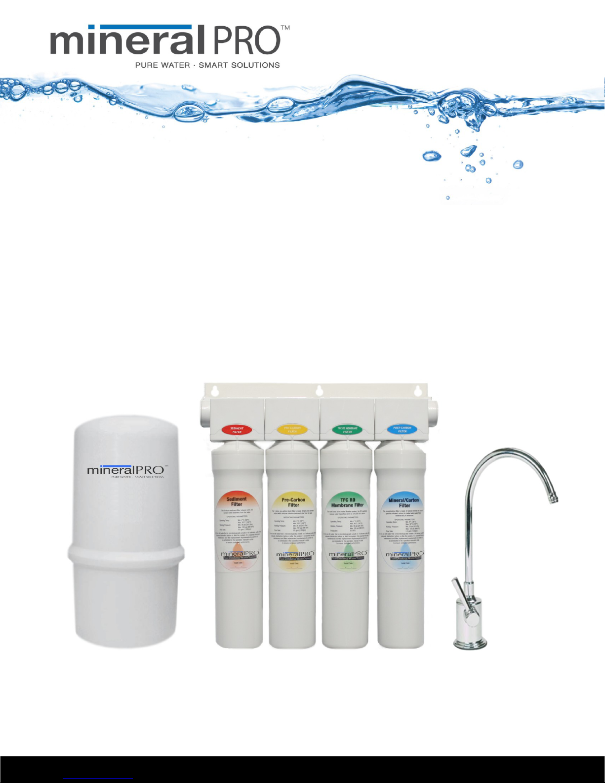
MineralPRO – RO
Installaon, Operaon, & Maintenance Manual
MineralPRO Mfg. T F
MineralPRO Mfg. PO Box 1499, Parksville BC Canada V9P 2H4 T 250.586.6667 F 250.586.6670
www.mineralpr o . c o m
Page 2

Manual Edition: Jan/15/2010
NOTE:
It is end users responsibility to ensure that this system is installed according to all local jurisdiction
codes and regulations.
Thank you for your purchase of a state of the art MINERALPRO Reverse Osmosis (RO) water treatment system.
Water quality concerns are becoming more of a focus for the public. This MineralPRO water treatment system
has been designed and tested to provide you with high quality water for years to come. The following is a brief
overview of the system.
Your Reverse Osmosis System:
Osmosis is the process of water passing through a semi permeable membrane in order to balance the
concentration of contaminants on each side of the membrane. A semi permeable membrane is a barrier that will
pass some substances like clean water, but not other substances such as salts and minerals.
Reverse osmosis uses a semi permeable membrane; however, by applying pressure across the membrane, it
concentrates contaminants on one side of the membrane, producing clean water on the other. This is why RO
systems produce both clean drinking water and waste water that is flushed from the system. Your system is a
Five Stage RO which is based upon four treatment segments within one complete water filtration system. These
stages are as follows:
Stage 1 – Sediment filter, recommended change 6 months.
The first stage of your RO system is a five micron sediment filter that traps sediment and other particulate
matter like dirt, silt and rust which affect the taste and appearance of your water.
Stage 2 – Pre-Carbon filter, recommended change 6 months.
The second stage contains a carbon block filter. This helps ensure that chlorine and other organic materials are
removed from the water prior to the Reverse Osmosis Membrane stage.
Stage 3 – Reverse Osmosis Membrane, recommended change 2 years.
Stage three is the heart of the reverse osmosis system, the RO membrane. This semi-permeable membrane
will take out salts, minerals, metals, bacteria, viruses, cysts, and much more. Because the process of extracting
this high quality drinking water takes time, your RO water treatment system is equipped with a storage tank.
Stages 4 & 5 – Natural Mineral Balancing and Coconut Carbon Filter, recommended change 1 year.
The 4th and 5th stages are combined into a single filter cartridge. The Natural Mineral Balancing consists of
naturally occurring minerals which returns the water to its natural state by stabilizing the pH to slightly alkaline
and provides the water with healthy natural minerals. The Natural Coconut Carbon filter provides a final polish
for crystal clear, high quality, crisp tasting water!
Note: Filter replacements may vary based on quality of incoming water supply and/or volume of water usage.
Note: The RO membrane may require earlier replacement if water flow from the drinking faucet decreases
due to heavy contaminants.
- 1 -
www.mine r a l pro .com
Page 3

System Maintenance
Just because you can not taste it, does not mean that it is not there. Contaminants such as lead, chromium,
VOC’s and arsenic are undetectable to the taste. Additionally, over time if you do not replace the filter elements,
other bad tastes and odors will be apparent in your drinking water.
This is why it is important to change out your filter at the recommended intervals as indicated in this system
manual. Should you have any further questions please contact the dealer from whom you purchased the unit.
With proper installation and maintenance, this system will provide you with high quality water for years to
come.
Table of Contents
Operational Parameters: .................................................................................................................................... 3
Contents of MINERALPRO .................................................................................................................................... 3
Tools Recommended For Installation ................................................................................................................ 3
Step 1 – Determine Location for the Faucet ...................................................................................................... 4
Step 2 – Drill a Hole for the Faucet in a Stainless Steel Sink .............................................................................. 4
Step 3 – Drill a Hole for the Faucet in a Porcelain, Enamel, Ceramic on Metal or Cast Iron ............................. 5
Step 4 – Faucet Installation ................................................................................................................................ 5
Step 5 – Water Valve (Adapta-Valve) Installation .............................................................................................. 7
Step 6 – MINERALPRO Module Mounting ............................................................................................................ 7
Step 7 – Drain Saddle Installation ...................................................................................................................... 8
Step 8 – Tank Valve Installation ......................................................................................................................... 9
Steps 9 through 12 (Tube Connections) ............................................................................................................. 9
Quick Reference Tube Connections ............................................................................................................... 9
How to Use the Quick Connect Fittings on the RO Module ........................................................................... 9
Step 9 – White 3/8” Tube Connection (Tank <---> MINERALPRO) ..................................................................... 10
Step 10 – White ¼” Tube Connection (Adapta-Valve <---> MINERALPRO) ........................................................ 10
Step 11 – Blue 3/8” Tube Connection (Faucet <---> MINERALPRO) ................................................................... 10
Step 12 – Red ¼” Tube Connection (Drain <---> MINERALPRO) ......................................................................... 10
Step 13 – Install Cartridges .............................................................................................................................. 11
Step 14 – Start-Up Instructions ........................................................................................................................ 11
Maintenance Instructions ................................................................................................................................ 12
Cartridge Replacement Instructions ............................................................................................................ 12
Cartridge Replacement Schedule ................................................................................................................. 13
Annual Maintenance ................................................................................................................................... 13
Storage Tank Sanitization ............................................................................................................................................. 13
Drain Line Flow Restrictor ............................................................................................................................................. 13
Tank Air Pressure .......................................................................................................................................................... 14
Procedure for Extended Non-Use (2 months or longer) .............................................................................................. 14
Troubleshooting ............................................................................................................................................... 15
Service Record .................................................................................................................................................. 16
Limited Warranty ............................................................................................................................................. 17
- 2 -
www.mine r a l pro .com
Page 4
Operating Temperatures:
Maximum 100°F (37.8°C)
Minimum 40°F (4.4°C)
Operating Pressure:
Maximum 85 psi (6.0 kg/cm2)
Minimum 40 psi (2.80 kg/cm2)
pH Parameters:
Maximum 11
Minimum 2
Iron:
Maximum 0.2 ppm
TDS (Total Dissolved Solids)
< 1800 ppm
Turbidity
< 5 NTU
Operational Parameters:
Hardness: Recommended hardness should not exceed 10 grains per gallon, or 170 ppm. The system will
operate with hardness over 10 grains but the membrane life may be shortened. (Addition of a water softener
may lengthen the membrane life.)
Note: The operating pressure in your home should be tested over a 24 hour period to attain the maximum
pressure. If incoming pressure is above 85 psi a pressure regulator is recommended and if over 100 psi then a
pressure regulator is required.
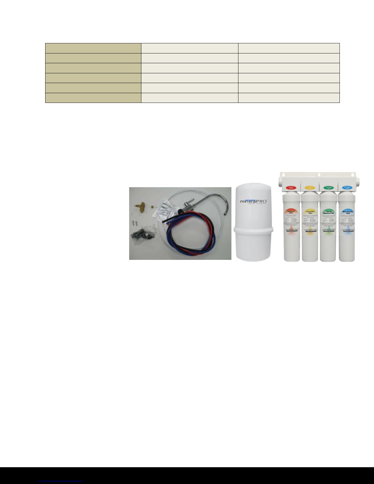
Contents of MINERALPRO
1 Plastic Storage Tank
1 MINERALPRO System
1 Parts Bag
1 Faucet Bag
1 Manual and Warranty
If any of the items are missing
please contact your dealer.
*NOTE: Extra parts are included in the parts bag for optional installation types.
Tools Recommended For Installation
Tube cutters
Phillips screw driver
Variable speed electric drill
Adjustable Wrench
Plumbers putty
Lubricating oil
¼” Drill bit for drilling plastic pipe
Stainless Steel Sink Type (If drilling hole is required)
1 1/4” Carbide tipped hole-cutter drill bit for stainless steel
Hole punch or large nail
Hammer
Porcelain, Enamel, Ceramic on Metal or Cast Iron Sink Type (If drilling hole is required)
1 1/4” Bi-metal hole saw drill bit
5/16th Carbide drill bit
Masking tape
- 3 -
www.mine r a l pro .com
Page 5

Step 1 – Determine Location for the Faucet
Note: Some sinks are predrilled or may have knockouts with 1 ½” or 1 ¼” diameter holes that can be used
for your RO faucet.
Determine the desired location for the faucet on your sink and check below the sink and countertop to
ensure clearance of any obstructions.
If the sink has a sprayer or soap dispenser, it may be disconnected for faucet installation. A pipe cap or plug
may be necessary to seal the sprayer connection.
To make a faucet hole (if sprayer hole or a secondary hole is not used) inspect under the sink area to make
sure the drill does not interfere with anything below. The faucet should be positioned so it empties into the
sink and the spout swivels freely for convenience.
If the sink has a hole that can accommodate the RO faucet, no drilling is required. Proceed with step 4 –
Mounting the Faucet.
For stainless steel sinks please see step 2. For Porcelain sinks please see step 3. For other sink types and
under-counter mountings please contact your dealer. If no locations are possible, please contact your dealer
about other faucet options.
Step 2 – Drill a Hole for the Faucet in a Stainless Steel Sink
Note: A variable speed drill with an 1¼” bi-metal hole saw drill bit or a carbide tipped hole cutter drill bit is
required to drill the hole. Drill lubricating oil or WD-40 is required to keep the drill bit cool.
Note: The use of eye protection is recommended.
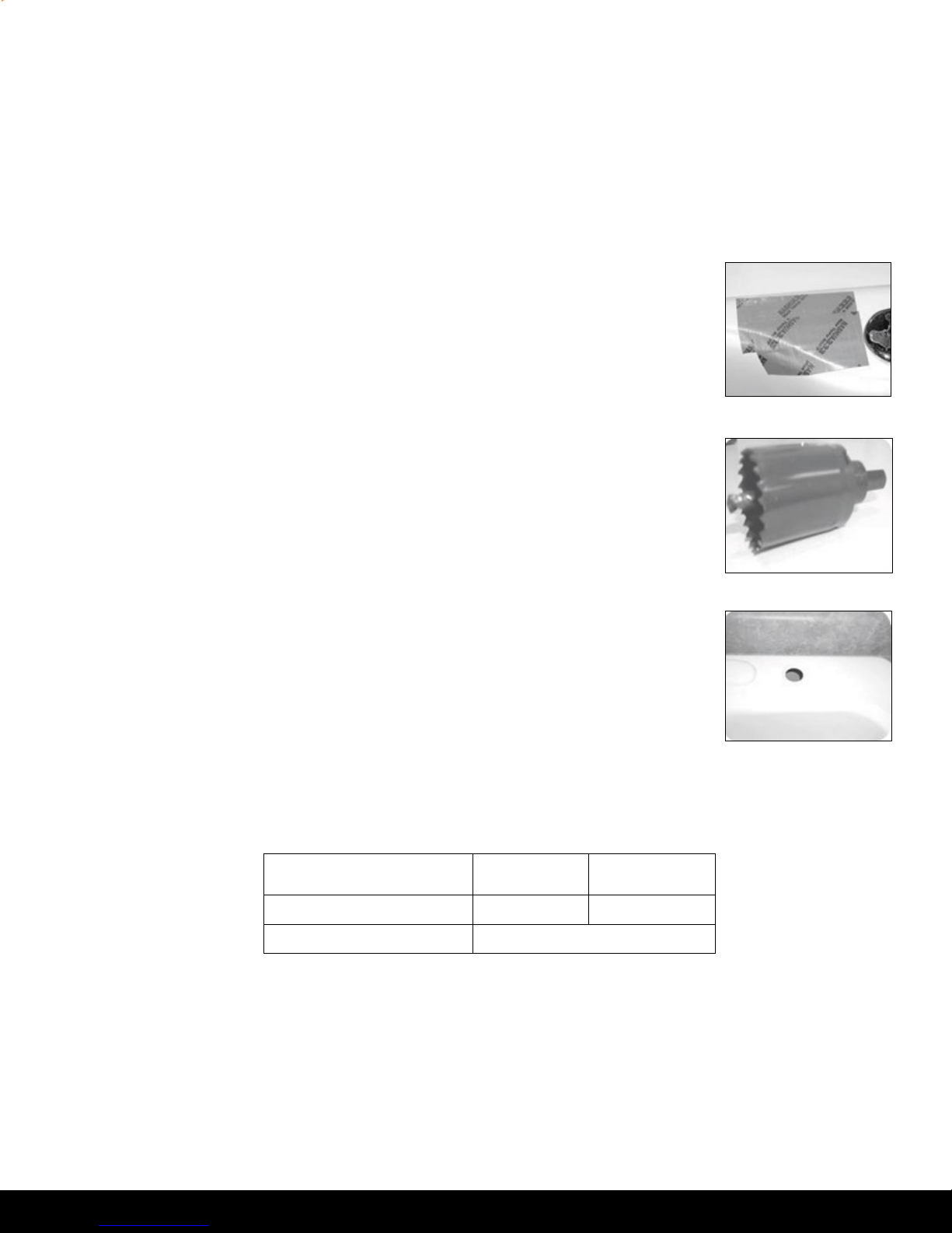
2(a) - Make a dimple in the sink in the center of the hole. Use a hole-punch or equivalent sized nail and a
hammer to create this small dent.
2(b) - Tape. To prevent the drill from “walking” as you drill, place a strip of masking tape over the dimple.
This keeps your drill on target.
2(c) - Lubricate. Form shallow putty around the hole area and fill with enough lubricant to lubricate drill bit.
Add more lubricating oil as needed.
2(d) - Drill. Make sure to wear your safety goggles. Use a carbide tipped metal hole cutter with a variable
speed drill. It is very important that you drill at a slow speed (180 rpm). Push carefully at first until the
pilot bit has penetrated the stainless steel sink. The drill bit or sink can be easily damaged if care is not
taken. Once the carbide teeth are touching the surface of the sink push down harder and maintain the
slow speed. Make sure to lubricate often. Only drill through the stainless steel for now.
2(e) - Remove tape and clean-up. Be very careful with the metal chips and the edge of the hole, they are
extremely sharp.
2(f) - Drill countertop if necessary. Inspect hole and determine if more drilling is required to drill through
any countertop that may be present under the sink. Use the appropriate drill bit suitable for counter
material. Clean-up when drilling is completed.
- 4 -
www.mine r a l pro .com
Page 6
Minimum
Maximum
Mounting Hole Size
1.00”
1.25”
Torque on Toggle Bolt
5 lb.in. (max)
Step 3 – Drill a Hole for the Faucet in a Porcelain, Enamel, Ceramic on Metal or
Cast Iron
Note: Precautions must be taken to penetrate the porcelain through to the metal base and prevent it from
chipping or scratching.
Note: The use of eye protection is recommended.
3(a) - Mark the center for the 5/16th hole. Place masking tape over location
where hole is to be drilled, and mark the center of the hole on the tape.
3(b) - Lubricate. Form shallow putty around the hole area and fill with enough
lubricating oil or liquid soap to lubricate drill bit. Add more lubrication as
needed.
3(c) - Drill pilot hole. Make sure to wear your safety goggles. Using a variable
speed drill on the slowest speed, carefully drill 5/16th pilot hole through all
layers. (If drill bit gets hot it may cause porcelain to crack or chip, add more
lubricating oil or liquid soap as needed.)
3(d) - Drill faucet hole. Make sure to wear your safety goggles. Using a 1 ¼” hole
saw, proceed to drill the large hole. Keep drill speed on the slowest speed
and use lubricating oil or liquid soap to the keep the hole saw cool during
cutting.
3(e) - Remove tape and cleanup. Carefully remove all sharp edges and clean-up
all lubrication. Make sure surroundings of the sink are cooled from drilling
before mounting the faucet to the sink after drilling.
3(f) - Drill countertop if necessary. Inspect hole and determine if more drilling is
required to drill through any countertop that may be present under the
sink. Use the appropriate drill bit suitable for counter material. Clean up
when drilling completed.
Step 4 – Faucet Installation
4(a) - Remove the black rubber gasket, faucet base and faucet spout from their respective plastic bags.
Remove the sticker from one side of gasket to reveal an adhesive surface. Slide gasket over water
tubes of the faucet with adhesive side towards the faucet. Firmly press gasket onto bottom of
faucet. Carefully remove the sticker from the other side of the gasket. Make sure not to detach the
gasket from the faucet. From above the sink, feed the faucet tubing and toggle bolt down through
the 1¼” mounting hole in the sink. Ensure that the soft rubber gasket is uniformly positioned in
between the base and the top of the sink.
- 5 -
www.mine r a l pro .com
Page 7
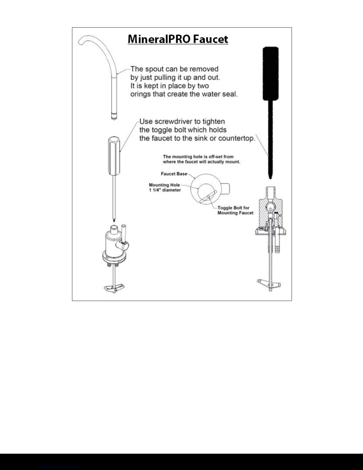
4(b) - Align the faucet base so that the handle is on the right side and the base is sitting flush on the sink
top. Turn the handle down (towards you) to the “ON” position to reveal the tightening screw
(located where the spout will be inserted). Using a Phillips head screwdriver, turn the screw
clockwise until the toggle bolt secures the faucet base snug onto the sink top, do not over torque
toggle bolt (5lb. in. max)
4(c) - Once the faucet base is securely fastened to the sink top, insert the faucet spout into the faucet
base until it is fully seated. Turn the handle up (away from you) to the “OFF” position.
4(d) - Completion of faucet installation (tubing connections) will be done later in this manual. Refer to
Steps 9 through 12 of this manual.
- 6 -
www.mine r a l pro .com
Page 8
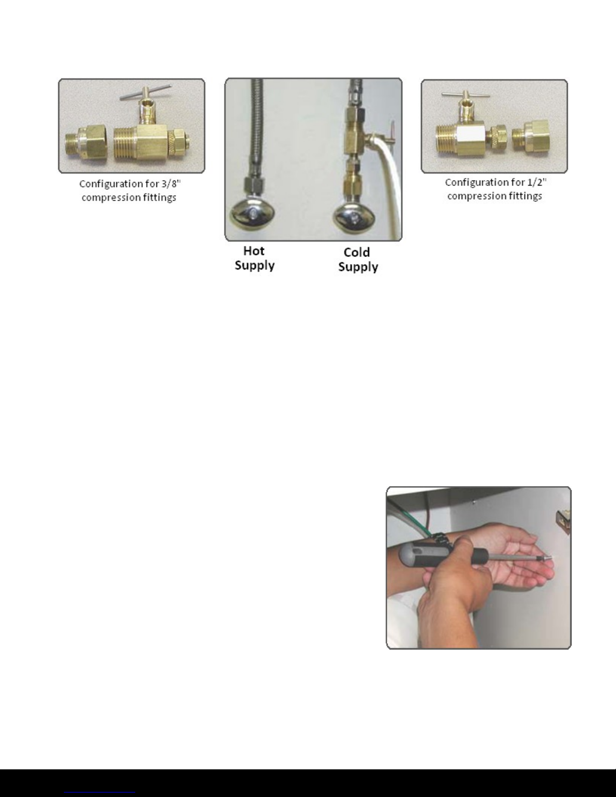
Step 5 – Water Valve (Adapta-Valve) Installation
5(a) - Locate the cold water supply under the sink.
5(b) - Turn off the cold water supply to the faucet by turning the angle stop valve completely off.
5(c) - Attach Adapta-Valve as illustrated in the three photos above, choosing the configuration that fits
your plumbing. (When attaching the Adapta-Valve to straight pipe threads, use Teflon tape on the
threads). The white tube from inlet side of RO module will be cut to length and attached later in the
installation.
Caution: Water supply line to the system must be from the cold water supply line only. Hot water will
severely damage your system.
Step 6 – MINERALPRO Module Mounting
6(a) - Determine best location for the RO module to be mounted
to allow for future system maintenance. The parts bag has
2 self tapping screws. Using a Phillips screwdriver, screw
them into the cabinet wall 10 ½” apart and 16” from the
bottom of the cabinet.
Note: Do not cut any RO system tubes at this time.
- 7 -
www.mine r a l pro .com
Page 9
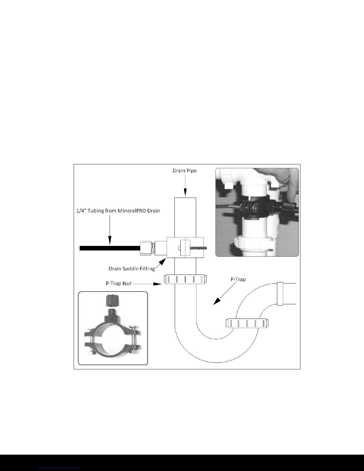
Step 7 – Drain Saddle Installation
Note: Drain Saddle fits standard 1 ¼” – 1 ½” drain pipes
Caution: If you have a garbage disposal, do not install the drain line near it. Installation of the drain line
must be either above the disposal, or if a second sink drain is available, install it above the cross
bar on the second sink. Installation of the drain line near a garbage disposal may cause the
drain line to plug.
7(a) - Gather the pieces of the drain saddle:
1 - Black compression nut
1 - Semicircle bracket with opening
1 - Semicircle bracket
2 - Screws
2 - Nuts for screws
1 – ¼” tube Insert
7(b) - Drill a ¼” hole through the drain pipe at least 1 ½” above the top nut of the P-trap to allow for the
removal of the P-trap if necessary. Assemble the drain saddle around the drain pipe. Position the
drain saddle over the drilled hole in pipe. Insert screw driver into the opening of the drain saddle
and align with drilled hole in drain pipe. Using Phillips screw driver tighten screws evenly and
securely on both sides of the drain saddle. Attach black compression nut, but do not tighten at this
time. The black tubing will be installed later.
Caution: Do not over tighten the screws. It may crack the drain saddle.
- 8 -
www.mine r a l pro .com
Page 10
Tube Color
Tube Size
Tube Connection
White
1/4"
Adapta-Valve to MINERALPRO
White
3/8"
Tank to MINERALPRO
Blue
3/8"
Faucet to MINERALPRO
Red
1/4"
Drain to MINERALPRO
Step 8 – Tank Valve Installation
8(a) - Make sure the O-Ring is located at the bottom of the recess for the
tank connection.
8(b) - Thread the plastic valve onto the tank fitting. Do not over tighten or
the valve could crack.
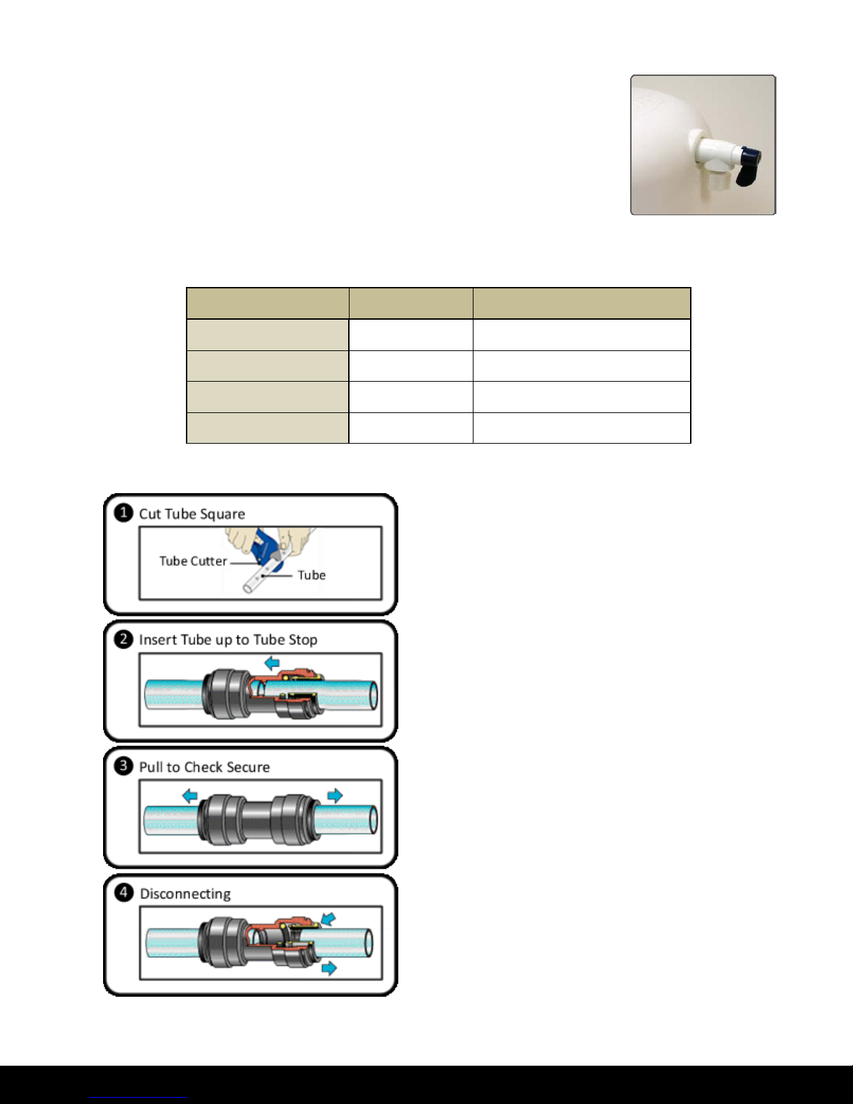
Steps 9 through 12 (Tube Connections)
Quick Reference Tube Connections
How to Use the Quick Connect Fittings on the RO Module
Cut tube square with tube cutter. Do not use hacksaw or
any other saw. O-ring must be free from burrs and sharp
edges.
Push the tube into the fitting, to the pipe stop. The collet
(gripper) holds the tube firmly in position and the 'O' Ring
provides a permanent leak proof seal.
Pull on the tube to check that it is secure. It is a good
practice to test the system prior to leaving site and /or
before use.
To disconnect, ensure the system is depressurized before
removing the tube. Push in collet squarely against face of
fitting. With the collet held in this position, the tube can be
removed. The fitting can then be reused.
- 9 -
www.mine r a l pro .com
Page 11
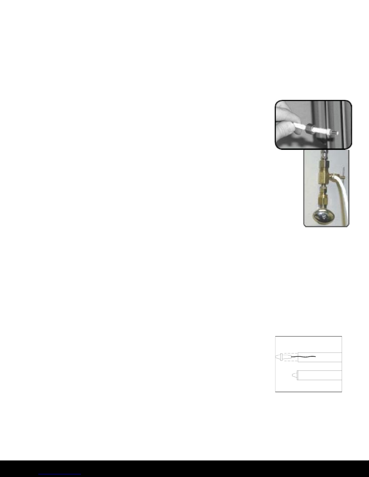
Flow Control
Step 9 – White 3/8” Tube Connection (Tank <---> MINERALPRO)
9(a) - Position tank in desired location. Stand it upright or lay it on its side. Measure the white 3/8” tube
from the MINERALPRO port marked TANK over to the tank and cut it to desired length.
9(b) - Insert the white 3/8” tube into the quick fit tank valve and MINERALPRO module port marked TANK.
Step 10 – White ¼” Tube Connection (Adapta-Valve <---> MINERALPRO)
10(a) - Remove a brass nut, plastic sleeve and insert from the parts bag. Place
nut on the white ¼” tube first, then the sleeve (small taper end of sleeve
must point to the end of tube) and then insert the plastic insert into the
end of the tube
10(b) - Insert the white tube with the nut, sleeve, and insert into the ¼” opening on
the Adapta-Valve until it stops. Slide nut and sleeve down and thread onto
the male pipe threads. Use a ½” wrench to securely tighten. Run the tube to
the inlet on the back of the MINERALPRO system. Leave enough tube so it
does not kink and cut the tube to desired length. Insert the tube into the
“inlet” port of the MINERALPRO system.
Step 11 – Blue 3/8” Tube Connection (Faucet <---> MINERALPRO)
11(a) - Insert the blue 3/8” tube from the faucet into the port on the system
marked “FAUCET”. Make sure the tube is pushed in all the way to the tube
stop. Keep the tube as short as possible for maximum operating flow and
pressure.
Step 12 – Red ¼” Tube Connection (Drain <---> MINERALPRO)
12(a) - Remove black plastic nut from drain saddle. Slip red tube through black nut. Press the plastic insert
into the end of the tube. Insert red tube into the opening in the drain saddle and hand tighten the
black nut, and add ¼ turn with a wrench.
12(b) - Run the tube from the drain saddle to the port labeled “Drain” on the
MINERALPRO unit. Leave enough tube so it does not kink. Cut the tube to
desired length.
12(c) - Insert the flow control into the end of the red tubing and insert the end of
the tube into the port labeled “Drain” on the back of the MINERALPRO unit.
- 10 -
www.mine r a l pro .com
Page 12
Step 13 – Install Cartridges
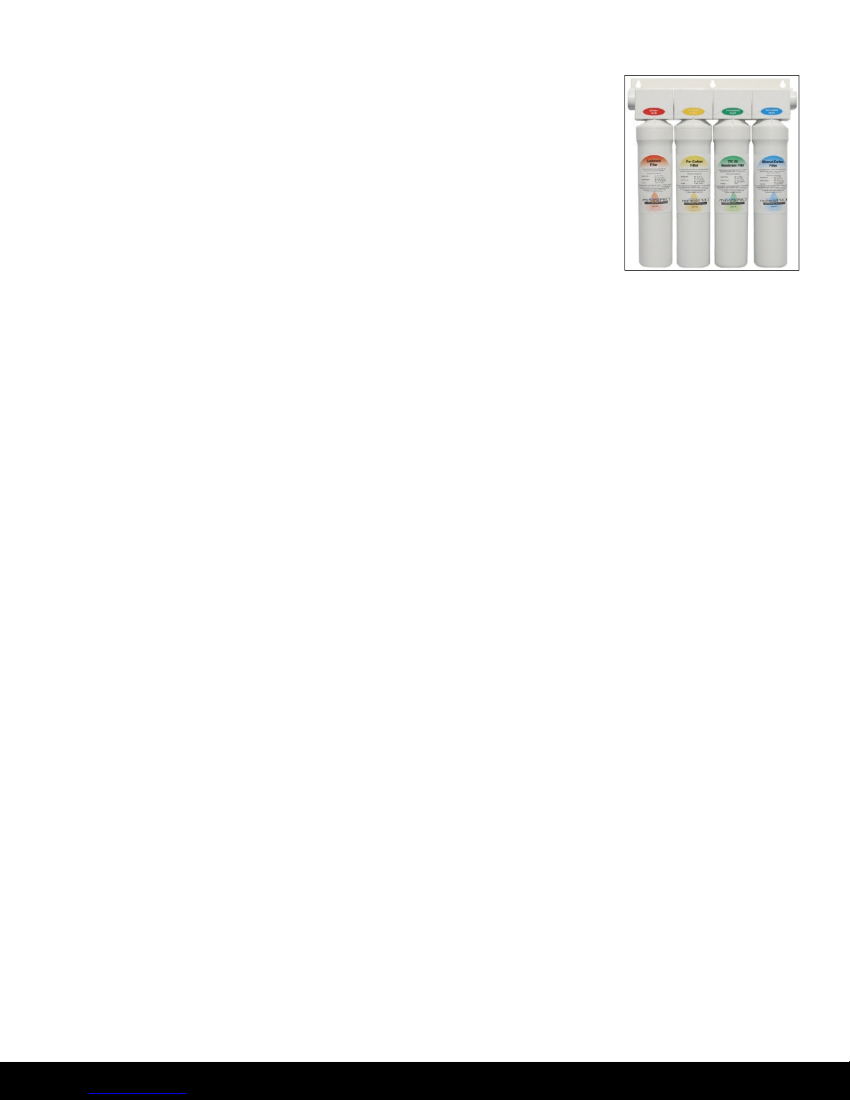
13(a) - Identify each cartridge and the proper location on the system by
matching the colors and description.
Stage 1 – Sediment Filter
Stage 2 – Pre-Carbon Filter
Stage 3 – TFC RO Membrane (TFC – Thin Film Composite)
Stages 4/5 – Mineral/Carbon Filter
13(b) - Write the date of installation on each cartridge and insert each cartridge with a ¼ turn in the
clockwise direction. The cartridge is installed properly when the label is facing toward the front of
the unit. Record the installation information on the system service record.
Note: The cartridge heads swivel up and down for easy access. See Cartridge Replacement
Instructions on page 14 for further information.
Step 14 – Start-Up Instructions
14(a) - Turn on the incoming cold water at the angle stop valve. Open the needle valve on the brass
Adapta-Valve by turning counter clockwise. Check the system for leaks and tighten any fitting as
necessary. (Check frequently over the next 24 hours to ensure no leaks are present).
14(b) - If system is connected to an ice maker, turn the ice maker off (or do not allow water to flow to the
ice maker) until Step 14(e) “flushing” is complete and the tank has been allowed to completely fill.
Connection from the RO to the ice maker system should have an in-line valve installed before the
ice maker so it can easily be closed to prevent water flowing to the ice maker during start up and
periodic maintenance. Your RO tank must be allowed to fill up in order for the ice maker system to
work properly. (If you are installing an ice maker kit from MineralPRO, tee off of the blue line
between MINERALPRO system and faucet).
14(c) - Open the RO faucet and leave it open until water begins to trickle out (it will come out slowly).
14(d) - After water trickles out of the faucet, close the faucet so the tank will fill with water. The tank will
take 4 to 8 hours to fill completely depending on the production capability of the membrane, local
water temperature and pressure.
14(e) - After the Tank has filled, open the faucet to flush the tank completely to remove carbon particles
from final filter. Repeat this step two more times. The fourth tank can be used for drinking. Note:
The flushing of the tank 3 times is only necessary during initial installation. This should take
about a day to complete.
NOTE: This reverse osmosis system contains replaceable components critical to the efficiency of
the system. Replacement of the reverse osmosis component should be with one of identical
specifications, as defined by the manufacturer, to assure the same efficiency and
contaminant reduction performance. Periodic inspection and following proper system
maintenance is critical for continued performance.
- 11 -
www.mine r a l pro .com
Page 13
Maintenance Instructions
Cartridge Replacement Instructions
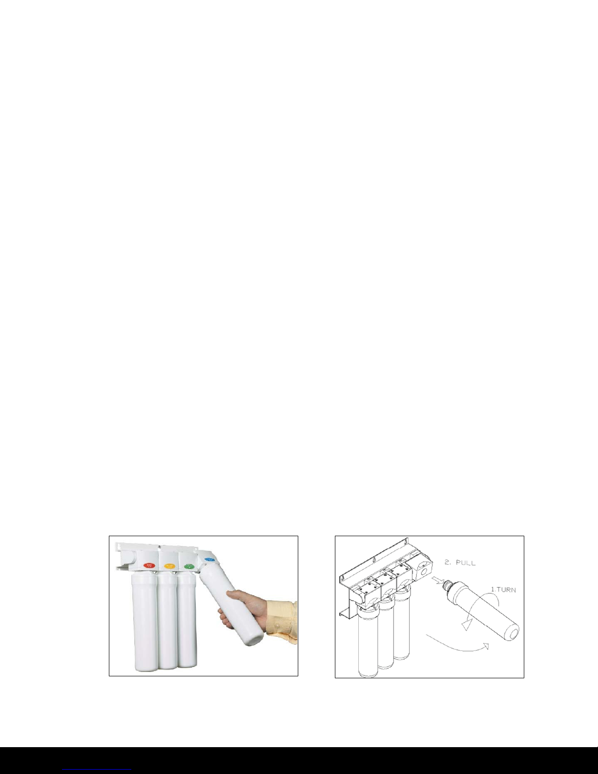
Cartridge replacement is made easy with the MineralPRO’s Quick Change system. The cartridge heads
contain built in check valves and shutoff valves so that the cartridges can be changed without shutting
off the water supply or the storage tank. The cartridge head is also hinged to allow easy access to the
cartridges.
The following steps should be followed to change the cartridges.
Note: A small amount of water may be released when changing cartridges.
Step 1 Grasp the old cartridge and pull it towards you.
Step 2 Rotate the old cartridge ¼ turn counter clockwise.
Step 3 Remove the old cartridge and dispose of it.
Step 4 Remove the protective cap from the new cartridge.
Step 5 Write the date of installation on the new filter cartridge.
Step 6 Orient the new cartridge with the label facing to the left (9 o’clock position)
Step 7 Push the new cartridge into the head and rotate it clockwise ¼ turn.
Step 8 Return new cartridge to the vertical position.
Step 9 Wipe up any spilled water.
Step 10 Open the faucet to flush the tank completely to remove carbon particles from final filter.
Step 11 Close the faucet and allow tank to fill up.
Step 12 Record the date and information of the cartridge change on the system service record.
- 12 -
www.mine r a l pro .com
Page 14
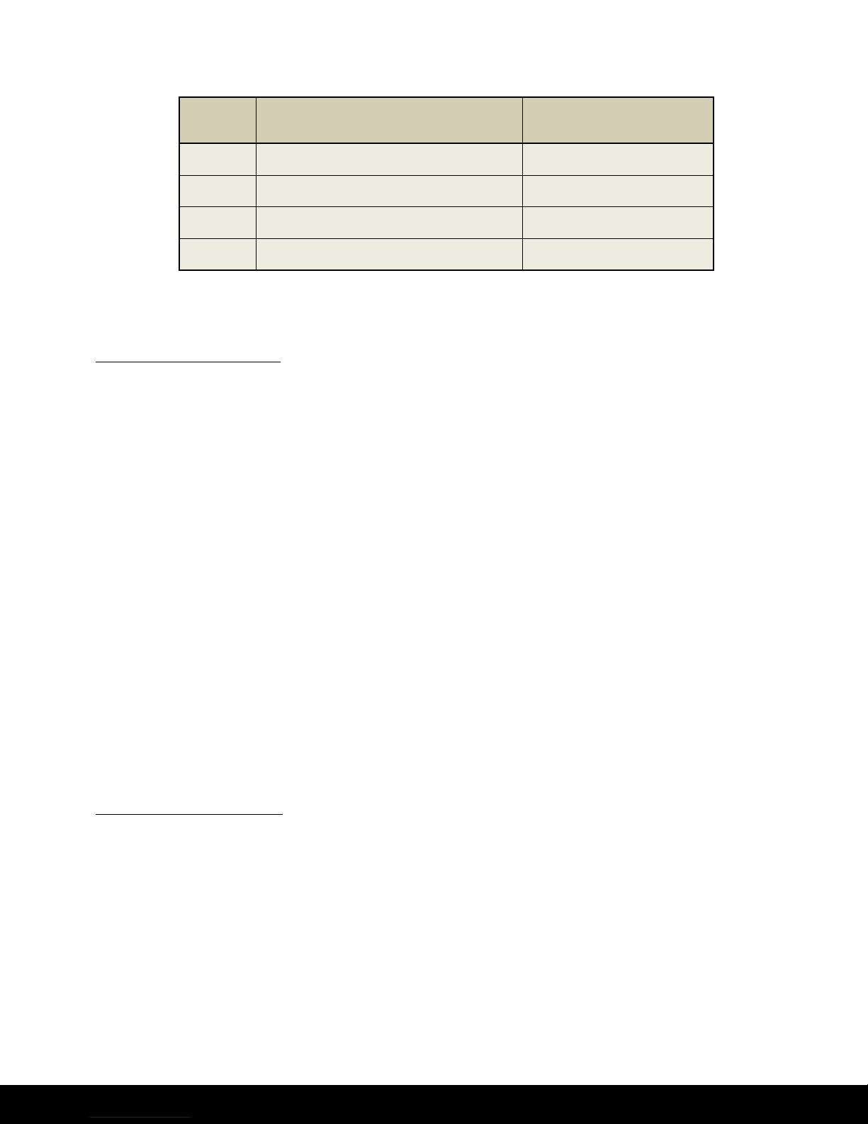
Stage
Cartridge Name
Replacement Schedule
1
Sediment Filter
6 months
2
Pre-Carbon Filter
6 months
3
TFC RO Membrane
2 years
4/5
Mineral/Carbon Filter
1 year
Cartridge Replacement Schedule
Annual Maintenance
Storage Tank Sanitization
Storage tank sanitization should be done when the 4/5th stage of MineralPRO unit is replaced.
However, it is important to sanitize the system prior to replacing the filter, as outlined in the
instructions below:
Step 1 Turn off the incoming water supply at the Adapta-Valve.
Step 2 Open the faucet, allow the tank to empty, and then close the faucet.
Step 3 Remove the tubing between the tank and the MINERALPRO unit at the MINERALPRO Drain
fitting.
Step 4 Drain the water from the tubing and pour one teaspoon of household bleach into the
tubing. A syringe works well for this.
Step 5 Reinstall the tubing between the tank and the MINERALPRO unit.
Step 6 Turn on the water supply at the Adapta-Valve.
Step 7 Allow the MINERALPRO unit to fill the tank. (Takes approx 4-10 hours)
Step 8 Open the faucet and allow the tank to empty, and then close the faucet.
Step 9 Replace the 4/5th stage Mineral/Carbon filter cartridge.
Drain Line Flow Restrictor
The drain line flow restrictor should be cleaned yearly to prevent blocks in the line.
Step 1 Turn off the incoming water supply at the Adapta-Valve.
Step 2 Remove the red tubing from the back of the MINERALPRO unit.
Step 3 Remove and inspect the orifice in the flow restrictor. Clean if necessary.
Step 4 Reinstall the flow restrictor into the end of the red tubing.
Step 5 Reinstall the red tubing onto the back of the MINERALPRO unit.
Step 6 Turn on the water supply at the Adapta-Valve.
- 13 -
www.mine r a l pro .com
Page 15
Tank Air Pressure
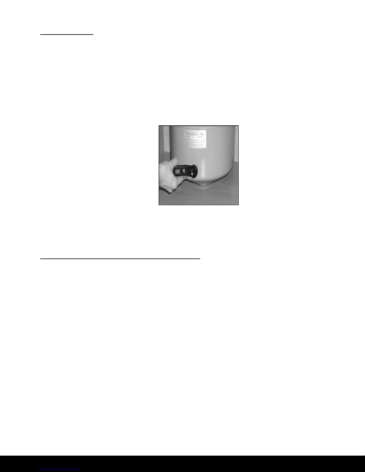
The storage tank air pressure should be checked yearly to ensure proper operation.
Step 1 Turn off the incoming water supply at the Adapta-Valve.
Step 2 Open the faucet, allow the tank to empty, and then close the faucet.
Step 3 Check the pressure in the tank using a tire pressure gauge on the air valve.
Step 4 The tank pressure should be between 5-7 psi. Use a bicycle pump to add air if necessary.
Step 5 Turn on the water supply at the adapta valve.
Note: Tank comes pre-charged from factory but should be tested annually after the first year of
service.
Procedure for Extended Non-Use (2 months or longer)
If the system will not be used for an extended period (more than 2 months) perform the following:
Step 1 Turn off the incoming water supply at the Adapta-Valve.
Step 2 Open the faucet, allow the tank to empty, and then close the faucet.
Step 3 Remove and discard the sediment filter, pre-carbon filter, and post carbon filter cartridges.
Step 4 Remove the RO membrane cartridge. Place it in a zip lock bag and store in rerigerator.
Step 5 To begin using the unit again, follow the startup and tank sanitization procedures.
- 14 -
www.mine r a l pro .com
Page 16

Problem
Cause
Solution
1. Low/Slow
Production
Low water pressure
Assure a minimum of 40 psi incoming water pressure.
MineralPRO sells a booster pump if home water pressure is
low. Make sure water supply is turned on and Adapta-Valve is
all the way open.
Crimps in tubing
Check tubing and straighten or replace as necessary.
Clogged pre-filters
Replace pre-filters.
Fouled membrane
Replace membrane and clean flow restrictor.
Tank valve closed
Open valve on storage tank
2. Colored Water
Air in System
Air in the system is a normal occurrence with initial start
up of the RO system. This milky look will disappear
during normal use within 1-2 weeks. If condition reoccurs
after filter change, drain tank 1 to 2 times.
3. Water constantly
running/unit will not
shut off
Low water pressure
See #1 Above
Fouled membrane
Replace membrane.
High water pressure
Check incoming water pressure to make sure it does not
exceed 100psi. A pressure relief valve or pressure regulator
valve may be necessary.
4. Noise from faucet or
drain
Air gap faucet
Inherent sound with air-gap faucets.
Location of drain saddle
See diagram for proper location of drain saddle.
Higher capacity membrane
Normal with high capacity membrane.
High water pressure
Check incoming water pressure to make sure it does not
exceed 100psi. A pressure relief valve or pressure regulator
valve may be necessary.
5. Faucet leaks from
the air gap feature
Crimp or loop in drain line
Straighten red 1/4" drain tube. Cut off any excess tubing.
Drain tube
clogged/restricted
Caused from dishwasher or garbage disposal. Disconnect the
1/4" red tube at the drain, clean the 1/4" red tube out with a
wire, and then reconnect.
6. Small amount of
water in storage tank
System is just starting up
Normally it takes 4-10 hours to fill tank. Note: Low pressure
and/or temperature can drastically reduce production rate.
Low water pressure
See #1 Above
Too much air in tank
Add air if below 5 psi and bleed if above 5 psi. Check only
when tank is empty of water. See page 15.
7. Water leaks from
the filter housing
Not properly tightened.
Tighten the cartridge.
Missed or kinked O-ring
Turn off water supply. Release the water pressure, remove
the filter cartridge and replace the O-ring. Make sure the Oring is seated correctly in the filter cartridge before
reinstalling the filter cartridge.
Troubleshooting
www.mine r a l pro .com
- 15 -
Page 17
Date
1st Stage
Sediment
(6 months)
2nd Stage
Pre-Carbon
(6 months)
3rd Stage
RO Membrane
(2 years)
4th Stage
Carbon/Mineral
(1 year)
NOTES:
Service Record Serial No. ___________________
Date of Purchase: _______________ Date of Install: ________________ Installed by: _________________
- 16 -
www.mine r a l pro .com
Page 18

Limited Warranty
This Reverse Osmosis System is warranted against defects in material and workmanship for a period of one
year from the date of installaon, not to exceed 2 years from the date of manufacture. Expendable items such
as filter cartridges and membranes are not covered by this warranty.
How to obtain Warranty Service: Contact the dealer that you purchased the system from. MineralPRO will
work in conjuncon with our dealer to repair or replace
defecve. No returns will be accepted without proper return authorizaon.
What this warranty does not cover: This warranty does not cover defects resulng from improper installaon,
abuse, misuse, misapplicaon, improper maintenance, neglect, alteraon, accidents, casuales, water
pressure spikes, fire, flood, freezing, or other such environmental factors. Return shipping charges are not
included in this warranty and are t
he responsibility of the end user.
This warranty will be void if defects occur due to failure to observe the following condions:
1. The Reverse Osmosis System must be hooked up to a potable municipal or well cold water supply.
2. The hardness of the water should not exceed 10 grains per gallon, or 170 ppm.
3. Maximum incoming iron must be less than 0.2 ppm.
4. The pH of the water must not be lower than 2 or higher than 11.
5. The incoming water pressure must be
between 40 and 100 pounds per square inch.
6. Incoming water to the RO cannot exceed 105 degrees F (40 degrees C.)
7. Incoming TDS/Total Dissolved Solids not to exceed 1000 ppm.
8. Do not use with water that is microbiologically unsafe or of unknown quality without adequate disinfecon
before or aer the system.
at our discreon any unit that is determined to be
This warranty does not cover any equipment that is relocated from the site of its original installaon.
LIMITATIONS AND EXCLUSIONS:
MINERALPRO WILL NOT BE
RESPONSIBLE FOR ANY IMPLIED WARRANTIES, INCLUDING THOSE OF MERCHANTABILITY AND FITNESS FOR A PARTICULAR PURPOSE. MINERALPRO WILL NOT BE RESPONSIBLE FOR ANY
INCIDENTAL OR CONSEQUENTIAL DAMAGES, INCLUDING WATER DAMAGE, TRAVEL EXPENSE, TELEPHONE
CHARGES, LOSS OF REVENUE, LOSS OF TIME, INCONVENIENCE, LOSS OF USE OF THE EQUIPMENT, AND
DAMAGE CAUSED BY THIS EQUIPMENT AND ITS FAILURE TO FUNCTION PROPERLY. THIS WARRANTY SETS
FORTH ALL OF MINERALPRO'S RESPONSIBILITIES REGARDING THIS EQUIPMENT.
OTHER CONDITIONS:
If MineralPRO chooses to replace the equipment, it may be replaced with recondioned equipment. Parts used in
repairing or replacing the equipment will be warranted for 90 days from the date the equipment is returned to you or
for the remainder of the original warranty period, whichever is longer. This warranty is not assignable or transferable.
MineralPRO Manufacturing Ltd. PO Box 1499, Parksville BC Canada V2P 2H4 T 250-586-6667 F 250-586-6670
- 17 -
www.mineralpr o . c o m
 Loading...