

Page 1

THE MINELAB EXPLORER II
Minelab Explorer II
!
™
P0591-A
1
4901-0047 Rev 1.0
"
Page 2

www.minelab.com
THE MINELAB EXPLORER II
© Minelab Electronics Pty Ltd
This document contains proprietary information which is protected by
copyright. Apart from any use as permitted under the Copyright Act
1968, no part may be reproduced by any process without written
permission from Minelab Electronics Pty Ltd, 118 Hayward Avenue,
T orrensville, SA 5031, Australia.
WARNING. This document contains Minelab Electronics Pty Ltd rights,
technical data or restricted rights data, or both. Patents and trademarks
apply.
Since there may be a range of options available in this detector
type, equipment may vary according to the model or items ordered
with your detector. Certain descriptions and illustrations may differ
(in this manual) from the exact model that you purchased. In
addition, Minelab reserve the right to respond to ongoing technical
progress by introducing changes in design, equipment and
technical features at any time.
2
Page 3

T ABLE OF CONTENTS
INTRODUCTION ................................................................................................................... 1
1
About this manual .............................................................................................................. .......................2
Introducing the Minelab Explorer II ......................................................................................................... 3
Minelab’s unique technology.................................................................................................................... 4
ASSEMBLY............................................................................................................................9
2
Unpacking your Explorer II [easy reference]....................................................................................... 10
Unpacking your Explorer II....................................................................................................................11
Assembling the detector ......................................................................................................................... 12
Connecting the search coil..................................................................................................................... 13
The shaft assembly ................................................................................................................................15
Connecting the shaft assembly.............................................................................................................. 16
The handle assembly ............................................................................................................................. 18
Headphones............................................................................................................................................ 20
Replacing and fitting the search coil....................................................................................................... 21
THE MINELAB EXPLORER II
contents
BATTERIES.......................................................................................................................... 23
3
The battery pack..................................................................................................................................... 24
Battery performance ............................................................................................................................... 27
THE CONTROL PANEL....................................................................................................... 29
4
The control panel [easy reference] ........................................................................................................ 30
Power and Backlight buttons ................................................................................................................. 31
Menu and Back buttons ......................................................................................................................... 32
Shortcut buttons ...................................................................................................................................... 33
Shift buttons ............................................................................................................................................ 35
3
Page 4

www.minelab.com
THE MINELAB EXPLORER II
T ABLE OF CONTENTS
QUICKSTART ......................................................................................................................37
5
Getting started......................................................................................................................................... 38
Beginner use .......................................................................................................................................... 39
Quickstart display [easy reference]....................................................................................................... 40
Quickstart’s Smartfind display ............................................................................................................... 42
The Iron Mask ........................................................................................................................................ 45
Quickstart’s Digital display .................................................................................................................... 47
Modifying the display............................................................................................................................. 48
Adjusting sensitivity ............................................................................................................................... 49
Adjusting threshold ................................................................................................................................. 50
Audio response....................................................................................................................................... 51
Audio menu............................................................................................................................................. 52
Audio: adjusting the volume................................................................................................................... 53
Audio: adjusting the tone ........................................................................................................................ 55
Audio: adjusting the sounds ................................................................................................................... 56
T esting target audio responses [tutorial] ................................................................................................ 58
Pinpointing the object.............................................................................................................................. 59
Recovering the object............................................................................................................................. 61
Selecting targets ..................................................................................................................................... 62
Selecting targets [easy reference] ......................................................................................................... 63
Accepting and rejecting targets [tutorial] ............................................................................................... 64
Advanced mode option........................................................................................................................... 65
contents
4
Page 5

THE MINELAB EXPLORER II
T ABLE OF CONTENTS
contents
ADVANCED USE .................................................................................................................67
6
Advanced mode’s Main Menu [easy reference] ................................................................................. 68
Starting in Advanced mode.................................................................................................................... 69
Advanced Mode’s displays [easy reference]...................................................................................... 70
Advanced mode’s Learn display [easy reference] ............................................................................... 71
Learning targets ...................................................................................................................................... 72
Learn’s target selection [tutorial] ............................................................................................................ 73
Advanced mode’s Edit display [easy reference]................................................................................. 75
Editing patterns ....................................................................................................................................... 76
Editing and saving target patterns [tutorial].......................................................................................... 77
Advanced mode’s Select menu............................................................................................................. 79
Saving targets......................................................................................................................................... 80
Audio menu............................................................................................................................................. 81
Options menu ......................................................................................................................................... 82
Options: noise......................................................................................................................................... 83
Options: response .................................................................................................................................. 84
Options: recovery .................................................................................................................................. 86
Settings menu ......................................................................................................................................... 87
5
Page 6

www.minelab.com
THE MINELAB EXPLORER II
T ABLE OF CONTENTS
USER INFO ......................................................................................................................... 89
7
Helpful hints............................................................................................................................................ 90
Battery performance comparisons ......................................................................................................... 92
User preferences.................................................................................................................................... 93
Control Panel button functions ............................................................................................................... 95
Quickstart menu structure ...................................................................................................................... 96
Advanced menu structure ...................................................................................................................... 97
Troubleshooting....................................................................................................................................... 98
Service repair form................................................................................................................................. 99
Warranty ............................................................................................................................................... 101
T echnical specifications for the Minelab Explorer II............................................................................ 102
Explorer model features ....................................................................................................................... 103
Glossary of terms................................................................................................................................. 104
Detector care and safety ...................................................................................................................... 108
contents
6
Page 7

THE MINELAB EXPLORER II
1
Introduction
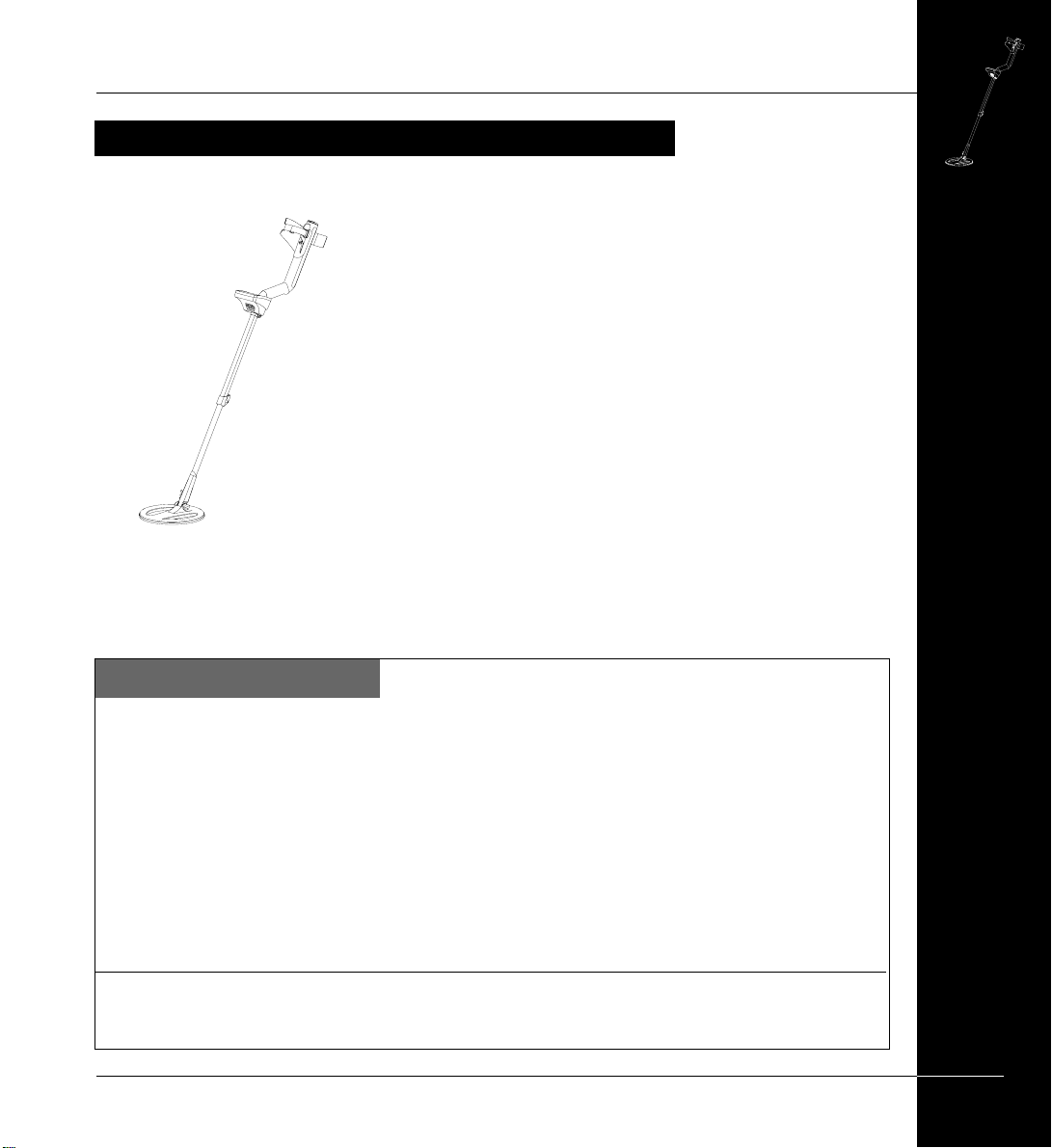
The Explorer II is the most
technologically advanced detector ever
produced.
It is possible to start treasure hunting as
soon as you have assembled the detector,
but it is worth familiarizing yourself with
its many features.
7
Page 8

www.minelab.com
P
I
N
P
O
I
N
T
I
R
O
N
MA
S
K
D
E
T
E
C
T
P
O
W
E
R
N
O
I
S
E
C
A
N
C
E
L
B
A
C
K
L
I
G
H
T
B
A
C
K
M
E
N
U
E
x
p
l
o
r
e
r
I
I
O
N
/
O
F
F
O
N
/
O
F
F
M
IN
E
L
A
B
IronI
n
THE MINELAB EXPLORER II
ABOUT THIS MANUAL
This manual is designed to introduce the detector’s features, give you step-by-step
directions for everything from assembling and adjusting your detector to basic
detector use and customizing your own advanced settings.
!
1. INTRODUCTION
Basic overview of the Explorer II
and this User’s Manual.
2. ASSEMBLY
This chapter provides details and
instructions on assembling and
adjusting the Explorer II.
3. BATTERIES
The Explorer II is powered by
alkaline batteries or a rechargeable
Nickel Metal Hydride (NiMH) battery
pack. This chapter provides details
on battery installation, use and
performance.
4. CONTROL P ANEL
This chapter is designed to familiarize
you with the various features of the
Explorer II control panel. A few
minutes spent reading this chapter will
be a worthwhile preliminary to basic
or advanced detecting.
"
5. QUICKST ART
However experienced you are at
using a metal detector, it is important
that you read this chapter to
understand how to use the Explorer II
in Quickstart mode.
6. ADVANCED USE
Once you are comfortable with basic
detector use and Quickstart it is time to
investigate the more advanced
features of the Explorer II.
7. USER INFO
This chapter provides a glossary of
terminology, user guides, technical
specifications, warranty and repair
details and troubleshooting tips.
8
ABOUT THIS MANUAL
Page 9
INTRODUCING THE MINELAB EXPLORER II
Thank you for purchasing a MinelabExplorer II detector. The
Explorer II is different to conventional metal detectors and features a
number of technological innovations and design features which are
introduced and explained in this manual.
The Explorer II is designed to locate valuable metal objects in a
wide variety of ground conditions including extreme salt conditions
and sea water, wet beach sand and highly mineralized ground
conditions. The detector’s simple-to-use control panel and fully
automatic Quickstart mode enable the beginner to start detecting
immediately after assembling the detector. Advanced mode’s options
will enable you to customize your detector for years to come.
Before you attempt to use your detector in the field, you should
P0591-A
follow the chapters of this manual to assemble, understand and
customize the Explorer II to suit your personal requirements. Please
read all the information thoroughly.
Minelab Electronics wish you every success in your treasure
hunting.
THE MINELAB EXPLORER II
Contact Minelab
If you have any questions or comments regarding the Explorer II or any other Minelab product,
please feel free to contact us via your local Authorized Minelab dealer, or write to us:
Minelab Electronics Pty Ltd
PO Box 537 Torrensville Plaza
South Australia 5031
AUSTRALIA
email: ho@minelab.com.au
tel: 61-8-8238 0888
Visit our site www.minelab.comfor the latest information on Minelab products and services.
Minelab USA
Minelab USA Inc
2700 E Patrick Lane, Suite 11
871 Grier Drive, Suite B1,
Las Vegas, Nevada 89120
Las Vegas, Nevada, 89119
UNITED STATES OF AMERICA
UNITED STATES OF AMERICA
email: minelab@minelabusa.com
email: info@minelabusa.com
tel: 1-702-891 8809
tel: +1 (702) 891 8809
Minelab International Limited
Laragh, Bandon
Co. Cork
IRELAND
email: minelab@minelab.ie
tel: 353-23 52101
INTRODUCING THE MINELAB EXPLORER
9
Page 10
www.minelab.com
THE MINELAB EXPLORER II
MINELAB’S UNIQUE TECHNOLOGY
The Explorer II is one of a new generation of detectors from Minelab. Its sleek, sturdy
design, innovative control panel and comprehensive targeting options set it apart from
any other detector available today.
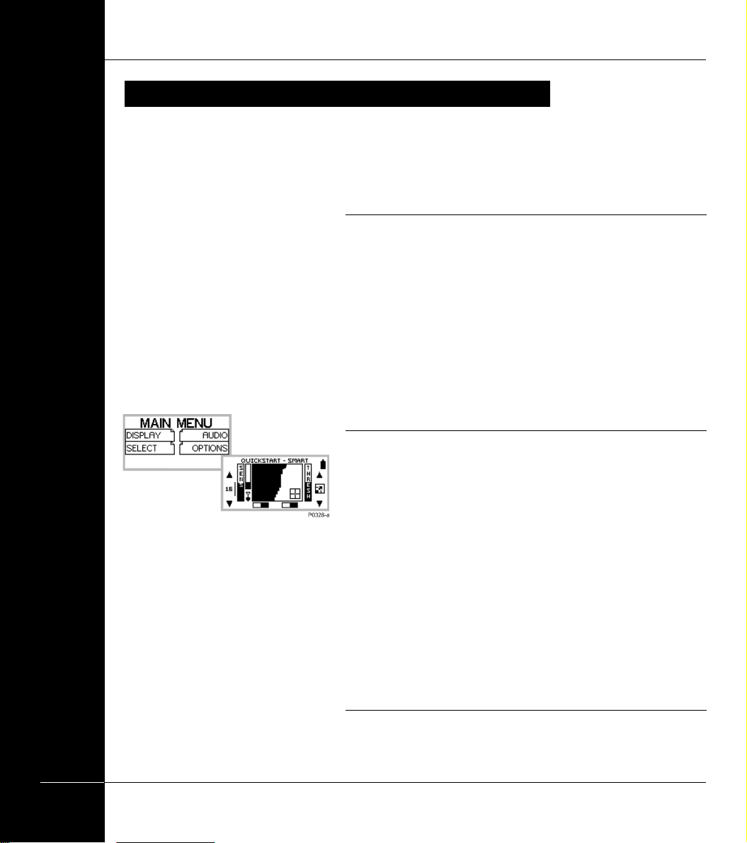
Two mode detecting
The Explorer II is so feature-packed that the research team at
Minelab decided to offer two modes of operation: fully automated
detection (Quickstart mode) and personally customized precision
detecting (Advanced mode).
All of the detector’s vital functions are common to Quickstart and
Advanced mode. Because the Explorer II is such an innovative
machine, even the seasoned treasure hunter will benefit from
beginning in Quickstart mode.
Quickstart mode
10
Smartfind display
Main Menu
Figure 1.1 Quickstart mode
MINELAB’S UNIQUE TECHNOLOGY
As soon as you have assembled the Explorer II, you are ready to
start detecting. When it leaves the factory, the detector is
programmed to start in Quickstart.
Quickstart settings are optimized to provide you with accurate
detection in most conditions you will encounter in the field, so you
can concentrate your attention on the objects you discover.
This manual’s Chapter 4: Control Panel, outlines all of the control
panel features needed to use your detector in Quickstart (or
Advanced mode) including shortcut buttons, special functions like
Pinpoint and adjusting your detector settings.
Chapter 5: Quickstart, explains basic use in detail and provides tips
on everything from sweeping the detector coil to digging up objects.
Advanced mode
Page 11

Smartfind display
Main Menu
Figure 1.2 Advanced mode
Factory Reset Power On Tune
THE MINELAB EXPLORER II
Once you are familiar with the feel and functions of the detector, it is
a simple matter to move into Advanced mode. This will enable you to
change the appearance of the display, modify audio responses,
specify custom targets and edit and save personal settings. Chapter
6: Advanced Use provides all of the information you need to
personalize your Explorer for specialized targeting.
Getting Lost?
If at any time you become a little confused with the settings for your
detector, or just want to brush up on basic detector use, it is simple to
reset the Explorer II to its original factory settings.
T urn the detector off and then PRESS AND HOLD THE POWER BUTTON
until a six-note musical tune is sounded (rising C-major chord). The
Minelab logo and the words ‘FACT ORY PRESETS’ will be briefly displayed
on the screen (as shown above).
This will return you to the original Quickstart mode settings. You can
resume basic detecting or make selections from the Main Menu.
MINELAB’S UNIQUE TECHNOLOGY
11
Page 12

www.minelab.com
THE MINELAB EXPLORER II
Discrimination
Discrimination is the ability of a
metal detector to identify the user’s
desired target (e.g. jewelry) and
eliminate signals from undesirable
material (e.g. nails).
Full Band Spectrum (FBS)
When developing Full Band Spectrum (FBS) technology, Minelab’s
scientists looked at improving the already successful Broad Band
Spectrum (BBS) technology used in previous Minelab detectors.
Discussions with seasoned treasure hunters from around the world
identified a number of possible enhancements for operators. The
improvements to the Explorer II detectors include:
The Explorer II can be programmed
in a number of ways to discriminate
against unwanted targets in different
types of ground.
Figure 1.3. Metal detector comparisons
• increased detection depth;
• accurate identification of targets to greater depth;
• enhanced detection of desired targets amidst iron trash;
• adjustments to improve operation for searching salt-water
beaches.
Most detectors on the market
operate on a single (or dual)
frequency, ranging from 1 to 70
kilohertz (kHz). Although this
technology has served the industry
well for years, Minelab’s scientists
found that a frequency that worked
well in one area would often offer
only marginal performance when
used in another location. Ground
mineralisation, trash content, and
target size all had an effect on how
effective a detector transmitting a single frequency would operate.
Full Band Spectrum technology combines Minelab’s existing multiple
frequency BBS technology with a powerful new microprocessor to
give:
12
• greater detecting depth;
• consistent sensitivity over a wide range of targets;
• less interference from electromagnetic sources;
• more accurate identification of target characteristics.
MINELAB’S UNIQUE TECHNOLOGY
Page 13

THE MINELAB EXPLORER II
Operating Frequencies
A metal detector’s
electromagnetic operating
frequencies are measured in
kiloHertz (kHz).
Low signal frequencies
(e.g. 1.5 kHz) penetrate deepest,
but sensitivity to smaller targets
is low.
On the other hand, higher
frequencies have a more
shallow depth of penetration
but high sensitivity to small
targets.
The Explorer II’s multiple-
frequency operation provides
the advantage of both.
The Full Band Spectrum (FBS) circuit automatically transmits 28
frequencies simultaneously. This increased frequency range means
that the signal received from the detector coil is analyzed from a
wide range of responses. This information is relayed to the operator
via the speaker or headphones and the control panel’s liquid crystal
display as an audio or visual target response.
Put simply, Minelab’s unique FBS technology means deep, sensitive,
accurate detecting.
Ground Compensation
The Explorer II uses a sophisticated approach to the elimination of
ground mineralisation. It uses advanced digital filtering to eliminate
the influence of ground signals.
You are now ready to proceed to Chapter 2: Assembly.
!
MINELAB’S UNIQUE TECHNOLOGY
13
Page 14

www.minelab.com
THE MINELAB EXPLORER II
14
Page 15

2
Assembly
This chapter provides details and
instructions on assembling and
adjusting the Explorer II.
THE MINELAB EXPLORER II
15
Page 16

www.minelab.com
THE MINELAB EXPLORER II
UNPACKING YOUR EXPLORER II
easy reference
RECHARGEABLE
BATTERY PACK
ACCESSORY BOX CONTAINING
CAR CHARGER & MAINS CHARGER
HANDLE ASSEMBLY
MAIN CARTON
• HANDLE ASSEMBLY
(CONTAINING ALKALINE
BATTERY PACK)
• UPPER SHAFT ASSEMBLY
• LOWER SHAFT ASSEMBLY
• SEARCH COIL (NUT & BOLT FOR
COIL)
• HEADPHONES
• RECHARGEABLE BATTERY PACK
ACCESSORY BOX
• ARMREST STRAP AND BUCKLES
• CAR CHARGER
• MAINS CHARGER
DOCUMENTATION
UPPER SHAFT ASSEMBLY
LOWER SHAFT ASSEMBLY
SEARCH COIL
P0592-A
DOCUMENTATION PACK
• MANUAL
• FIELD GUIDE
• WARRANTY CARD
16
UNPACKING YOUR EXPLORER
Page 17

UNP ACKING YOUR EXPLORER II
List of Parts
The box in which the Explorer II is shipped should contain the items
illustrated on the facing page. Please check that all of these items are
in the box. If any of these components are missing, contact your
Minelab dealer immediately.
Accessories
The following items are available for purchase separately:
• NiMH Battery Pack (spare)
• NiMH Battery Pack (high capacity)
• 8” Coil with Lower Shaft
• Weatherproof Control Box Cover
• Spare Coil Covers
• Carry Bag
THE MINELAB EXPLORER II
• Minelab Cap, Minelab Poloshirt.
For further information on these and other Minelab
products, contact your Minelab dealer.
You can also visit us on the web
UNPACKING YOUR EXPLORER
17
Page 18

www.minelab.com
THE MINELAB EXPLORER II
ASSEMBLING THE DETECTOR
Handle assembly
Shaft assembly
Search coil
P0591-A
18
Please follow these instructions to assemble the Explorer II. Refer to
the drawings to identify parts and how they are positioned. The
detector’s components are organized into three categories:
• the search coil;
• the shaft assembly, made up of the upper shaft and lower
shaft;
• the handle assembly, made up of the handle, armrest and
control box.
NOTE To avoid difficulties or damage to the detector’s
electronic components, it is strongly recommended you
follow the sequence of instructions for assembly.
Please contact your Minelab dealer for further instructions should
any difficulties arise.
ASSEMBLING THE DETECTOR
Page 19

THE MINELAB EXPLORER II
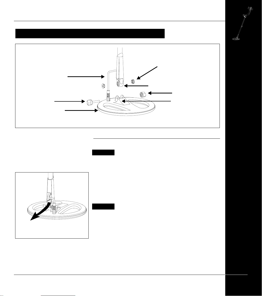
CONNECTING THE SEARCH COIL
The search coil transmits electromagnetic signals into the ground and receives
the response.
Rubber Washer
Coil Cable
Coil Yoke
Yoke Nut
Yoke Bolt
Search Coil
Figure 2.1 Connecting the search coil
to the lower shaft
Yoke Bracket
P0608-A
Connecting the search coil to the lower shaft
Figure 2.1–2.3
CAUTION DO NOT attempt to disconnect the coil cable
where it enters the search coil itself. They are shipped
pre-assembled and any attempt to disconnect will void your
detector warranty.
T o attach the search coil to the lower shaft:
STEP 1 Place the search coil on a flat surface close to the coil yoke.
STEP 2 (Figure 2.2, following page) Plug the two black plastic
washers into the recesses provided on either side of the coil
yoke.
(Continued next page)
CONNECTING THE SEARCH COIL
19
Page 20

www.minelab.com
THE MINELAB EXPLORER II
STEP 3 Check the orientation of the search coil and shaft ensuring
that the open side of the yoke faces the ground.
STEP 4 (Figure 2.2) To join the shaft to the search coil, slide the
yoke into the yoke bracket on top of the coil.
STEP 5 (Figure 2.3) Insert yoke bolt through the search coil’s yoke
bracket and the coil yoke. Fasten with the yoke nut
provided, being careful not to damage the thread of the nut
by over-tightening. This may need to be loosened to adjust
the coil to a comfortable detecting angle.
P0605-A
Figure 2.2 Inserting coil yoke into
bracket
P0606-A
Figure 2.3 Securing yoke to search
coil
You are now ready to proceed to the shaft assembly.
20
CONNECTING THE SEARCH COIL
Page 21

THE MINELAB EXPLORER II
THE SHAFT ASSEMBL Y
The shaft assembly is made up of the upper and lower shafts connected by the shaft
camlock. The assembly houses the coil cable and connects the search coil to the
handle assembly. These instructions assume that the search coil is connected to the
lower shaft.
Camlock Released
P0601-A
Figure 2.4 Feeding coil cable into upper shaft
Shaft assembly
Search Coil
Shaft Camlock
Upper Shaft
Figure 2.5 Sliding lower shaft into
upper shaft
P0602-A
Figure 2.4, 2.5
T o assemble the lower and upper shaft:
CAUTION Release the shaft camlock lever before inserting
the lower shaft.
STEP 1 (Figure 2.4) Feed the coil cable which is inside the lower
shaft through the inside of the upper shaft.
STEP 2 (Figure 2.5) Slide the lower shaft entirely into the upper shaft
until the camlock rests against the yoke.
STEP 3 Pull the coil cable’s metal connector through the open end of
the upper shaft until it ‘dangles’ from the opening.
You are now ready to connect the shaft assembly to the
handle assembly.
21
THE SHAFT ASSEMBLY
Page 22
www.minelab.com
THE MINELAB EXPLORER II
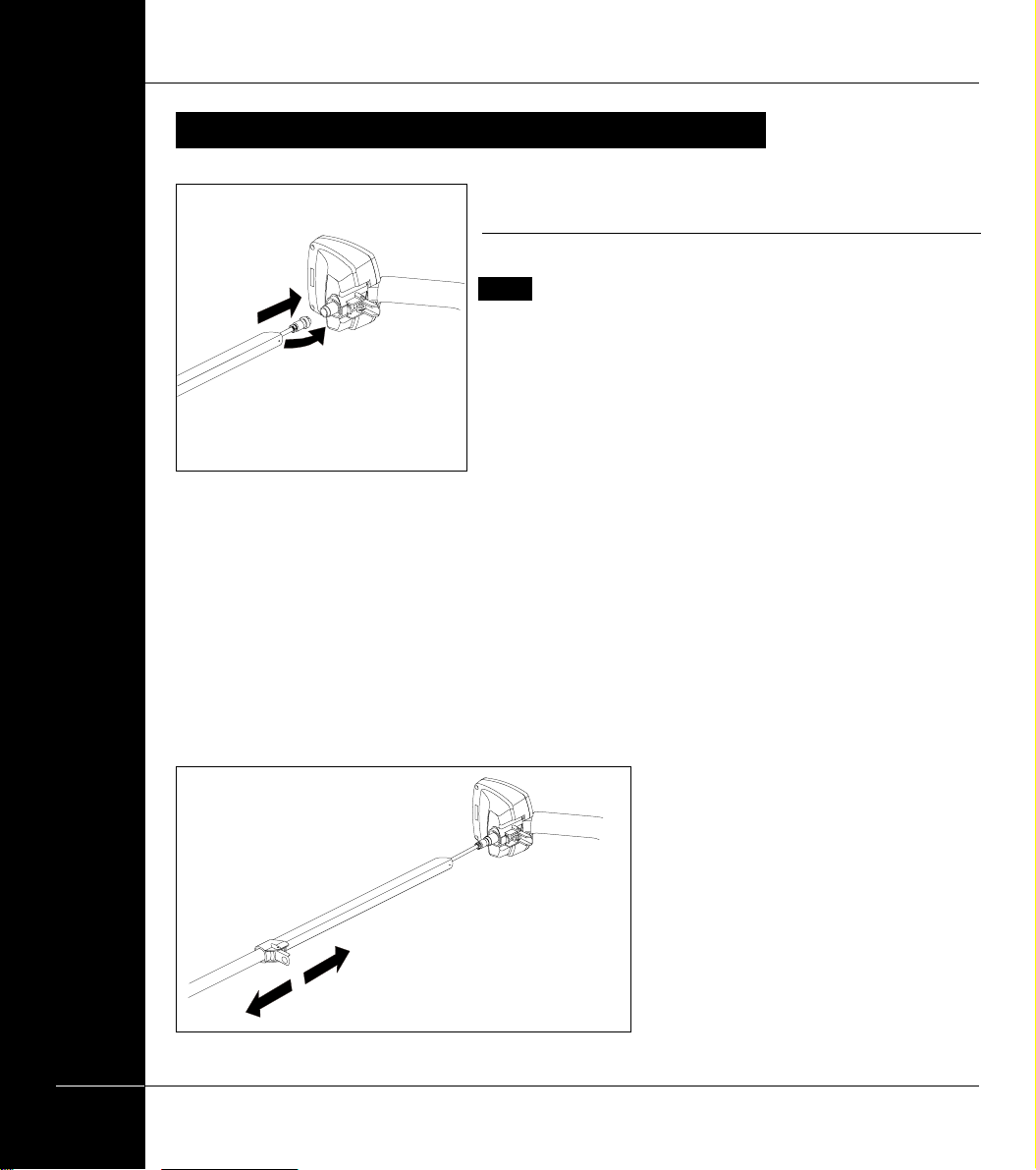
CONNECTING THE SHAFT ASSEMBL Y
Connecting the shaft assembly to the handle
assembly
Figure 2.6–2.9
NOTE Shaft orientation: camlock is on lower side of upper
shaft.
T o connect the shaft assembly to the handle assembly:
P0597-A
Figure 2.6 Attaching coil cable to
control box
STEP 1 (Figure 2.6) Release the control box camlock lever to the
open position.
STEP 2 (Figure 2.6) Align the connections and push the coil cable
connector into the socket underneath the handle assembly
control box. Ensure the connector’s threaded bracelet is
firmly secured.
STEP 3 (Figure 2.7) To prevent the coil cable from ‘bunching’,
extend the lower shaft from the upper shaft by approximately
15cm (6 inches).
STEP 4 (Figure 2.8) Making sure that the control box camlock lever
is in the released position, push the upper shaft firmly into
the control box until you feel it has reached the back of the
control box.
22
P0614-A
Figure 2.7 Preventing the coil cable
‘bunching’
CONNECTING THE SHAFT ASSEMBLY
Page 23

P0598-A
Figure 2.8 Inserting shaft assembly
into control box
THE MINELAB EXPLORER II
STEP 5 Secure upper shaft in position by locking the control box
camlock.
STEP 6 (Figure 2.9) Adjust shaft to the desired length and then lock
with shaft camlock lever.
STEP 7 (Figure 2.9) Tilt the search coil to the most comfortable
angle, keeping in mind it will need to be parallel to the
ground during detecting.
NOTE To avoid difficulty securing the control box camlock
lever, ensure the shaft camlock is released to allow greater
shaft movement.
You are now ready to proceed to the handle assembly.
Figure 2.9 Adjusting the shaft and
angle of the search coil
Coil not connected?
$
These instructions require the
search coil to be connected to the
lower shaft. For directions on this
procedure, refer to page 13.
P0599-A
23
CONNECTING THE SHAFT ASSEMBLY
Page 24

www.minelab.com
THE MINELAB EXPLORER II
THE HANDLE ASSEMBL Y
The handle assembly is made up of the armrest, straps and the control box. It is
connected to the shaft assembly by the control box camlock.
Adjusting the armrest assembly
Figure 2.10
T o adjust armrest:
STEP 1 Loosen the screw in the center of the armrest (turn counter-
clockwise). Use a screwdriver or the edge of a coin.
STEP 2 Slide armrest to your desired position. Your hand should
comfortably grip the angled neck of the handle assembly,
P0268-C
Figure 2.10 Armrest adjustment
with the detector feeling like an extension of your forearm.
STEP 3 Gently remove your arm.
STEP 4 Tighten screw (clockwise) to lock into position.
24
THE HANDLE ASSEMBLY
Page 25

Figure 2.11 Fitting buckle to armrest strap
THE MINELAB EXPLORER II
Fitting the armrest strap
Figure 2.11–2.13
T o fit and adjust the armrest strap:
STEP 1 (Figure 2.11) Thread the strap through the buckle openings
as illustrated.
STEP 2 (Figure 2.12) Clip both buckles into the openings at each
outer side of the armrest.
STEP 3 T est by sliding your arm underneath the strap and resting
your forearm on the armrest (which should be adjusted to a
comfortable setting).
STEP 4 (Figure 2.13) Loosen strap by tilting the edge of the buckle
out to release it from the armrest. Undo the velcro and pull
the buckle outwards (towards yourself). Clip the buckle back
into place and tighten the strap by pulling up (in the direction
of the top arrow in Figure 2.13).
The armrest should now be adjusted to your satisfaction. Next time
you use your detector, all you will need to do is click the buckle back
into the armrest.
Figure 2.12 Fitting armrest strap to
armrest
Figure 2.13 Tightening armrest strap
25
THE HANDLE ASSEMBLY
Page 26

www.minelab.com
THE MINELAB EXPLORER II
HEADPHONES
Headphone
Attaching headphones
Figure 2.14
The use of headphones when treasure hunting with the Explorer II
will avoid disturbing others in the area. The reduced power
demands of the headphones will also extend the battery life.
Socket
The socket for the headphone plug is located in the top right of the
rubber seal at the top of the handle assembly . The headphones may
be plugged into this socket or unplugged at any stage of operation.
P0595-A
Figure 2.14 Inserting headphone
Congratulations! Your Explorer II is now assembled. You are
now ready to proceed to Chapter 3: Batteries.
!
Should you wish to remove the search coil, instructions
follow on the next two pages.
26
HEADPHONES
Page 27
REPLACING AND FITTING THE SEARCH COIL
Coil Cable
Yoke Bolt
Search Coil
THE MINELAB EXPLORER II
Rubber Washer
Coil Yoke
Yoke Nut
Yoke Bracket
P0608-A
Figure 2.14 Replacing the search coil
Pull cable down
from inside
shaft/yoke
Figure 2.15 Removing cable
P0607-A
Replacing the search coil
Figure 2.14–2.16
CAUTION DO NOT attempt to remove the coil cable from the
search coil. Any attempt to disconnect will void your
detector warranty.
T o replace the search coil:
STEP 1 Disconnect the shaft assembly from handle assembly by
reversing the procedure outlined in Connecting the shaft
assembly on page 16.
CAUTION DO NOT attempt to remove the shaft assembly
without disconnecting the coil cable from the control box.
STEP 2 Separate the two shaft assemblies by releasing the shaft
camlock and sliding the lower shaft out.
STEP 3 (Figure 2.14) Loosen the yoke nut and carefully remove the
bolt from the yoke bracket. This removes the yoke from the
search coil. Be careful not to lose the two plastic washers.
(Continued next page)
27
REPLACING AND FITTING THE SEARCH COIL
Page 28

www.minelab.com
THE MINELAB EXPLORER II
STEP 4 (Figure 2.15) Gently pull the coil cable from inside the yoke/
lower shaft.
STEP 5 (Figure 2.16). Carefully feed the coil cable of the new coil
back into yoke and lower shaft. Continue to feed the cable
into the shaft unitl the connector is visible at the top of the
shaft.
Note: It may be easier to pull the cable through the lower
shaft using a length of string or cord. Once this is completed
you should be able to see approximately 4 inches (100mm)
of cable between the coil yoke and the search coil. This is
the slack necessary to allow adjustment to the angle of the
search coil.
STEP 6 Re-attach the yoke and the search coil. Be careful not to
damage the thread of the nut by over-tightening. See Figure
2.2 and 2.3.
STEP 7 Reconnect cable to control box (as directed in Connecting
the shaft assembly, page 16).
28
Pull Coil Cable
up inside of
yoke/shaft
P0613-A
Figure 2.16 Removing the coil cable
REPLACING AND FITTING THE SEARCH COIL
Page 29

THE MINELAB EXPLORER II
P
I
N
P
O
I
N
T
I
R
O
NM
A
S
K
D
E
T
E
C
T
E
L
B
A
C
K
L
I
G
H
T
B
A
C
K
E
x
p
l
o
r
e
r
I
I
O
N/O
F
F
O
N/O
F
F
MINELAB
IronI
n
4
Control Panel
It is important to familiarize yourself
4
CONTROL PANEL
with the features of the Explorer II control
panel. A few minutes spent reading this
chapter will be a worthwhile preliminary
to basic or advanced detecting.
29
Page 30

www.minelab.com
4
CONTROL PANEL
THE MINELAB EXPLORER II
THE CONTROL PANEL
easy reference
As the control panel provides user access to all Explorer II functions, the
various buttons will be referred to throughout this User’s Manual. The
terminology will remain consistent with the elements labelled below and
will be a useful reference as you begin detecting.
2
6
1
6
7
30
THE CONTROL PANEL
3
4
1
Power button (see page 31)
Display screen (for details see page 40)
2
Main Menu button (see page 32)
3
Shortcut buttons (see pages 33-34)
4
5
Back button (see page 32)
Shift buttons (see page 35)
6
7
Backlight button (see page 31)
5
Page 31

3
Batteries
The Explorer II is powered by alkaline
batteries or a rechargeable Nickel Metal
Hydride (NiMH) battery pack. This chapter
THE MINELAB EXPLORER II
provides details on battery installation,
use and performance.
31
Page 32

www.minelab.com
THE MINELAB EXPLORER II
THE BA TTERY P ACK
The Explorer II is supplied with a sealed rechargeable Nickel Metal Hydride (NiMH)
battery pack and a battery pack designed to accept alkaline AA batteries. Removal
instructions apply to both types of pack. Battery installation instructions apply to
alkaline battery replacement only.
Removal of battery pack
Figure 3.1
CAUTION Ensure that the detector is turned OFF before
proceeding with any of the following directions.
STEP 1 Prop or rest the detector on a stable flat surface.
STEP 2 Lift the rubber cap of the battery handle assembly.
STEP 3 Raise the yellow tab. This releases the spring loaded battery
pack.
32
Figure 3.1 Removal of battery pack
Figure 3.2 Replacing alkaline
batteries
THE BATTERY PACK
STEP 4 Remove battery pack entirely from handle assembly .
Replacing alkaline batteries
Figure 3.2
STEP 1 Remove alkaline battery pack from handle assembly . Slide
the battery pack lid in the direction of the arrow to remove.
Place 8 x ‘AA’ cell alkaline batteries inside. Make sure that
they are aligned as indicated on the label.
STEP 2 Replace the battery pack lid and slide the pack into the
compartment until it ‘clicks’ into place.
STEP 3 Replace the rubber cap, sealing the battery compartment.
NOTE High quality alkaline batteries are recommended to
optimise detector usage time. Rechargeable alkaline
batteries may be used but must be removed and recharged
separately.
NOTE
Page 33

THE MINELAB EXPLORER II
Recharging NiMH battery pack with the mains
charger
Figure 3.3
The Explorer II is provided with a sealed Nickel Metal Hydride
(NiMH) battery pack and a charger which plugs into a conventional
wall socket.
Figure 3.3 Recharging NiMH battery
pack
Safety Tip
Do not attempt to disassemble the
NiMH battery pack. If disposing of
pack, do not incinerate. Contact your
local authorities to enquire about
disposal or recycling facilities.
Recharging
$
NOTE The NiMH battery pack supplied with your detector
comes in the discharged condition. It is necessary to charge
it as explained below before operating the detector. The
batteries will reach their full capacity after several charge/
discharge cycles.
STEP 1 Remove battery pack as per instructions on previous page.
STEP 2 Insert the mains charger plug into the socket at the tapered
end of the battery pack.
STEP 3 Plug the mains charger into the wall socket and turn on the
switch (if switch available). Leave for about 18 hours to fully
recharge.
STEP 4 Remove the battery charger plug from the battery pack.
Slide the pack back into the handle assembly battery
compartment until it clicks into place.
Minelab’s batteries can be left on the
battery charger indefinitely without
harming the battery.
33
THE BATTERY PACK
Page 34

www.minelab.com
THE MINELAB EXPLORER II
Recharging
Recharging NiMH battery pack with the car charger
The Explorer II is provided with a car charger that boosts the
voltage of the car battery (usually about 12V) to a voltage sufficiently
high to charge the NiMH battery pack.
$
Minelab’s battery chargers are
suitable for the Explorer NiMH
battery pack only. The battery
chargers will not recharge
rechargeable alkaline batteries. Using
a non-Minelab charger with the
battery pack may damage it and will
void the product warranty.
STEP 1 Remove battery pack as per instructions on page 24.
STEP 2 Insert the car charger plug into the cigarette lighter socket.
STEP 3 Insert the car charger plug into the socket at the tapered end
of the battery pack. A small light on the car charger
illuminates indicating that the car charger is in operation.
NOTE Some vehicles will need the ignition to be switched on
to ‘accessories’ for power to be supplied to the charger.
STEP 4 Leave the battery to charge for about 18 hours for a
complete recharge. If the battery was not completely
discharged, the charging time will be shorter.
The car charger is provided with a 3AG 2Amp fast fuse for short
circuit protection that can be accessed by unscrewing the tip of the
cigarette lighter plug.
NOTE Charging the battery beyond full capacity will not
damage the NiMH battery pack, but it could gradually
discharge your car battery.
34
THE BATTERY PACK
Page 35

BA TTERY PERFORMANCE
Figure 3.4 Battery life indicator
Battery Life
Full
battery power
Low
battery power
Battery Performance
THE MINELAB EXPLORER II
Battery life indications
Figure 3.4
Visual indication – The battery life indicator appears on all of the
Explorer detect screens. The battery will be fully shaded at
maximum battery charge. When this shaded area nears the bottom,
the detector will begin to sound its low battery warning.
Audio indication – When the alkaline or NiMH batteries approach
the point at which they do not supply enough power to operate the
Explorer II, a falling extended chord is emitted from the speaker (or
headphones). When this low battery warning is heard, there will be
only a few minutes of life left in the batteries. It is recommended that
the batteries be replaced or recharged as soon as possible to avoid
missing any targets. When the battery symbol is completely empty,
the detector will sound an extended ‘dropping’ tune and display a
message immediately before turning itself off.
ALKALINE
NiMH 1600 mAh
NiMH 1800 mAh
12.5 hours
More detecting time?
T o extend battery life:
• use headphones
• turn off the backlight
• turn the detector off when not
in use
14
hours
14 hours
Notes supporting performance figures
Alkaline batteries will power the Explorer II for up to 14 hours of
constant use. The NiMH 1600 battery pack will power the detector
for up to 12.5 hours of constant use and the NiMH 1800 battery pack
for 14 hours. Battery performance is charted in Chapter 7: User
Info.
NOTE Unlike Nickel Cadmium batteries, the NiMH battery
pack DOES NOT have to be flattened to be recharged.
Whenever the detector has been unused for a lengthy
period, recharge the battery pack to ensure full performance.
There is no limit to the time the battery pack can be left on
charge.
You are now ready to proceed to Chapter 4: Control Panel.
!
BATTERY PERFORMANCE
35
Page 36

www.minelab.com
4
CONTROL PANEL
THE MINELAB EXPLORER II
CONTROL BUTTON FUNCTIONS ... INCLUDE?
36
Page 37

5
Quickstart
However experienced you are at using a
metal detector, it is important that you
read this chapter to understand how to
use the Explorer II in Quickstart mode.
THE MINELAB EXPLORER II
5
QUICKSTART
37
Page 38

www.minelab.com
5
QUICKSTART
THE MINELAB EXPLORER II
GETTING STARTED
Now that your detector is assembled, batteries inserted and you are familiar with the control
panel, you should be ready to start detecting. This chapter on Quickstart is designed to be
the starting point for all users of the Explorer II.
Introducing Quickstart
POWER
P0400-B
P0400b
Figure 5.1 Quickstart’s opening screen
Display memory
The Explorer II’s factory setting is
to start in Smartfind for your first
detecting session.
If the alternative Digital display is
the last used, the Explorer II opens
with this screen next time you turn
on the detector. It also retains all
adjustments to
settings made in the previous
session (including those
made in Smartfind).
Figure 5.1
When you first turn on the Explorer II, the Quickstart Smartfind
display will appear and you are able to begin detecting. The
detector is prepared to respond to non-ferrous targets while filtering
out ground signals.
The following pages in this chapter outline the basics of metal
detecting and use of the Explorer II. Y ou will learn how to interpret
its responses to targets and make your own adjustments to the
settings.
Regardless of your level of experience with metal detecting, Minelab
recommends you begin in Quickstart mode to familiarize yourself with
basic features and operation before experimenting with the
detector’s advanced features (detailed in Chapter 6: Advanced
Use).
A number of additional functions and features that are likely to be
accessed frequently while detecting are also explained.
These include:
• Target SENSITIVITY and THRESHOLD levels, adjusted with
shift buttons
• IRON MASK and PINPOINT, activated by shortcut buttons.
• MENU functions, accessed from the control panel shift
buttons. These enable you to adjust the display and audio,
define targets and move into Advanced mode.
38
GETTING STARTED
Page 39

BEGINNER USE
THE MINELAB EXPLORER II
CORRECT
INCORRECT
Figure 5.2 Sweeping the coil
Audio Overload
Sometimes it is possible that a
large object close to the search
coil will overload the detector’s
electronics. When this happens,
the Explorer II emits a low ‘warble’
which will repeat until the coil is
moved away from the source of the
overload.
Trying out the detector
Figure 5.2
Don’t try this at home!
If you attempt to begin detecting while you are inside your home,
you will quickly find that there are many metallic objects (such as
nails or reinforcing in the floor) which will result in almost
continuous detection. There will also be interference from TV sets
and other household appliances. Placing the sensitive detector coil
near large metallic objects can result in temporary saturation of the
sensor, meaning that it then cannot detect small objects. Therefore
it is best to turn your detector off and head outside, as far away as
P0265-A
you can from sources of electromagnetic disturbance.
Sweeping the coil
The Explorer II will perform at its best when the coil is kept in close
proximity to the ground. This will increase detection depth and
response to small objects. Becoming practised at sweeping the
coil is very important, as variation in coil height at the end of each
swing can cause confusing sounds and reduce detection depth.
Each sweep of the coil should overlap the last one (Figure 5.2).
This will ensure good ground coverage.
You think you’ve found something?
When an object is detected, the Explorer II emits an audio response
and visually displays a target classification on the control panel’s
screen.
Before you attempt to pinpoint or recover the object –
which is explained later in this chapter – it is vital you
understand how to interpret these audio and visual
responses.
This is explained over the next few pages.
5
QUICKSTART
BEGINNER USE
39
Page 40

www.minelab.com
THE MINELAB EXPLORER II
QUICKSTART DISPLAY
easy reference
The Quickstart display visually represents everything from target details to the
Explorer II’s operating settings. Quickstart’s Smartfind display (pictured below)
and alternate Digital display share many common elements.
5
QUICKSTART
10
8 8
1
3
5
4
6
2
7
9
40
QUICKSTART DISPLAY
Page 41

QUICKSTART DISPLAY
easy reference
THE MINELAB EXPLORER II
Sensitivity level. The sensitivity bar and
1
numbers indicate how responsive the detector is
to a target in the presence of ground noise and/or
electromagnetic interference. Numbers range
between 1 and 32. When the shift button next to
the number is pressed the detector moves
between semi-auto and manual sensitivity. See
page 49 for details.
Threshold level. The threshold setting controls
2
the audible level of threshold ‘hum’ during
detecting. When the shift button next to the
adjustment arrow is pressed, the threshold hum
increases or decreases. See page 50 for details.
Depth indicator. The clear portion of the depth
3
indicator represents the approximate distance of
a target below the coil. The top of the indicator
represents the position of the coil and the bottom
represents 300mm (12 inches) from the coil. The
bar will be clear if the target is too far from the
coil or its depth cannot be accurately gauged.
4
Iron Mask. This shaded block indicates whether
IRON MASK function is ON or OFF.
See page 45.
Smartfind display. The shaded and unshaded
5
areas of the screen are Smartfind’s preset
Discrimination setting. Smartfind also has an
alternative Iron Mask setting. See pages 42-43.
Pinpoint. This shaded block indicates whether
6
PINPOINT is ON or OFF. See page 59.
Battery life. This icon indicates the charge remaining
7
in the installed batteries. See page 27.
Adjustment arrows. Pressing shift buttons next to
8
these arrows increases or decreases preset
settings.
Full screen icon. Selection enlarges display to fill
9
screen. See page 48. This icon temporarily
changes to show the threshold level setting when
threshold is being adjusted.
Target crosshair. Represents the detected
10
object’s properties on a two-dimensional scale of
discrimination. See page 42-43.
5
QUICKSTART
QUICKSTART DISPLAY
41
Page 42

www.minelab.com
THE MINELAB EXPLORER II
QUICKSTART’S SMARTFIND DISPLAY
When first using the detector, you will see the Smartfind screen. Smartfind displays an
object's characteristics using a two-dimensional scale of target discrimination.
Two-dimensional discrimination
Figure 5.3
When an object is detected, Smartfind indicates what kind of
object you have found with a target crosshair. The location of this
crosshair on the Smartfind screen is based on Minelab's unique
Figure 5.3 Smartfind display with preset
Coins discrimination pattern
two-dimensional scale of discrimination. An understanding of this
will be helpful before Smartfind's Iron Mask and Discrimination
functions are explained in the next few pages.
Two-dimensional discrimination explained
5
QUICKSTART
42
The Explorer II rates detected objects according to their conductivity
(like most traditional detectors). What makes two-dimensional
discrimination unique is a rating of the same object's ferrous
content. Smartfind graphically represents both of these target
properties on the same display.
• The vertical dimension (or axis) rates the object on size/
conductivity.
QUICKSTART’S SMARTFIND DISPLAY
Page 43

THE MINELAB EXPLORER II
Discrimination
Discrimination is the ability of a
metal detector to identify the user’s
desired target (e.g. jewelry) and
eliminate signals from unwanted
material (e.g. nails).
The Explorer II can be programmed
in a number of ways to discriminate
against unwanted targets in different
types of ground.
• The horizontal dimension (or axis) rates the extent of the
object’s resemblance to ferrous characteristics.
• The object’s cross-referenced rating is represented by a
‘target crosshair’ inside the rectangular display area.
Interpreting target responses
Conductivity
• Objects with high conductivity (e.g. large silver coins, copper
items) will cause the target crosshair to appear at the top of
the Smartfind screen.
• Objects with low conductivity (e.g. small alloy coins, foil) will
cause the target crosshair to appear at the bottom of the
Smartfind screen.
Along with the type of metal, the size of objects will have some
effect on the conductivity rating for targets. Generally , the larger
the target, the higher the corresponding conductivity rating (and
proximity of the target crosshair to the top of the screen).
Ferrous content
• Objects with high ferrous content cause the target crosshair
to appear on the left of the screen unless its rating would
situate the object in the dark area of the discrimination pattern
(see page 44).
5
QUICKSTART
• Objects with low ferrous content (e.g. jewelry, coins) cause
the target crosshair to appear on the right of the screen.
The preset discrimination setting is designed to search for Coins.
NOTE Both ferrous and non-ferrous objects have varying
degrees of inductive response to electromagnetic waves.
This characteristic – in addition to conductivity – allows for
more accurate identification of targets.
QUICKSTART’S SMARTFIND DISPLAY
43
Page 44

www.minelab.com
THE MINELAB EXPLORER II
Introducing Discrim
Discrim (an abbreviation of Discrimination) instructs the detector to
accept some types of targets and reject others. It uses Smartfind's
two-dimensional discrimination, allowing you to specify one or more
target patterns for detection.
5
QUICKSTART
Figure 5.4 Smartfind’s preset Discrim
function
Smartfind Discrimination pattern
Figure 5.4
When you begin in Quickstart, you will see a Smartfind display
resembling Figure 5.4. This display shows that the detector is
ready to operate in its preset Coins Discrim function.
The discrimination pattern represents the typical characteristics of
non-ferrous coins (actually a composite of hundreds of coins from
around the world). When the search coil passes over an object
matching the conductive and ferrous characteristics of coins, the
target crosshair will appear in the clear area and a target response
will sound. Objects outside of the accepted (clear) area are not
displayed and the threshold ‘hum’ is temporarily silenced. The target
crosshair will remain locked in the position of the last accepted target.
The discrimination pattern 'maps' the specific ferrous and conductive
properties of coins, providing excellent accuracy in detection of this
particular type of target.
NOTE Quickstart offers a range of discrimination patterns
which may be used on their own or in combination. This is
detailed in Selecting Targets, page 62.
44
QUICKSTART’S SMARTFIND DISPLAY
Page 45

THE IRON MASK
THE MINELAB EXPLORER II
Adjusting the Iron Mask
Figure 5.5
Pressing the IRON MASK shortcut button on the control panel will
display the Iron Mask adjustment screen.
Figure 5.5 Adjusting the Iron Mask
Iron Mask Shortcut
The Iron Mask shortcut button on
the control panel allows you to
switch between Iron Mask and
Discrimination.
Before you experiment with this,
an understanding of the features
of these functions will greatly
assist in deciding which will
locate the kind of targets you want
and how to adjust the Explorer II
to suit your preferences.
Preset Level
The Explorer II's Iron Mask is set at a rating of -6. This is suitable
when detecting non-ferrous metals.
Detecting more ferrous objects
If you want target responses from more ferrous objects (e.g. war
relics) it is necessary to reduce the level of ferrous rejection. This
is done by pressing the bottom left shift button next to the slider
control, reducing the extent of the Iron Mask. You may need to
experiment a little with the settings.
Detecting all ferrous objects
If you wanted to detect all objects, regardless of ferrous content,
ferrous rejection can be reduced to a minimum level of -16. The
screen will be completely clear and all objects will sound a target
response.
Rejecting all ferrous objects
If you want target responses to be suppressed for all ferrous
objects, the Iron Mask may be increased to a level of 0. This is
represented by the mask extending to half way across the
Smartfind screen (as depicted in the section explaining
two-dimensional discrimination, see page 42).
5
QUICKSTART
The tutorials featured later in this
chapter also assume a basic
understanding of Iron Mask and
Discrimination functions.
45
THE IRON MASK
Page 46

www.minelab.com
THE MINELAB EXPLORER II
Figure 5.6 Smartfind in Iron Mask
Operating in Iron Mask
Figure 5.6
Pressing the IRON MASK shortcut button again will display a
Smartfind screen resembling Figure 5.6. This display shows that the
detector is ready to operate in Iron Mask. This function is
programmed to reject ferrous targets and make it easier for you to
find more desirable (non-ferrous) objects like coins and jewelry .
Iron Mask is preset to reject ferrous objects at a level suitable for
basic detecting. This is shown in Figure 5.5 as a rating of -6 with
the dark area filling the left third of the screen. Smartfind will not
display an object when its target crosshair would appear in this
dark, masked area of the screen and the ExplorerII’s threshold
‘hum’ will disappear momentarily .
However, if you wish to locate specific types of objects you may
need to modify the ExplorerII's level of ferrous rejection. This is
done by adjusting the Iron Mask as explained previously on page
45.
5
QUICKSTART
46
THE IRON MASK
Page 47

QUICKSTART’S DIGITAL DISPLAY
Digital display
Figure 5.7, 5.8
When the Smartfind screen is displayed, pressing the DETECT
shortcut button on the control panel switches to the Explorer II’s
P0611-A
Figure 5.7 Quickstart’s Digital Display
P0612-A
Figure 5.8 Digital as full screen display
Preferred Display
alternative Digital display.
The display rates both the ferrous content and the conductivity of an
object with numbers from 0-31. The number for ferrous content is
under the label ‘Fer’ and that for the conductivity is under the label
‘Cond’. A value of 0 represents low ferrous content and 31
represents high ferrous content. Similarly, 0 represents low
conductivity and 31 represents high conductivity.
The right of the digital read-out you will see an icon representing the
possible target and, in full screen display, a list of displaying up to
three possible target classifications.
THE MINELAB EXPLORER II
The Explorer II remembers which
display was last used in your
detecting. If this happens to be
Digital, this display will appear
next time you turn on the detector.
It should be noted that any
adjustments to discrimination that
are made in Smartfind will be
retained and used in Digital.
It is important to note that the discrimination settings (either the
current Discrimination Pattern or the Iron Mask are still active and
targets outside the accepted area will not update the display. If you
want to adjust the discrimination, simply press the DETECT button to
return to the Smartfind display.
HINT The digits shown in Digital display are a numeric
estimation of the horizontal and vertical position of the
target crosshair displayed in Smartfind mode (that is, its
ferrous and conductivity rating).
As you familiarize yourself with each display, try switching
from one to the other to compare the results.
QUICKSTART’S DIGITAL DISPLAY
5
QUICKSTART
47
Page 48

www.minelab.com
5
QUICKSTART
THE MINELAB EXPLORER II
MODIFYING THE DISPLAY
Figure 5.9 Quickstart’s standard screen
Figure 5.10 Quickstart as full screen display
Full screen display
Figure 5.9, 5.10
If you wish to enlarge the Smartfind or Digital display during
detecting, it is possible to instruct the detector to remove the display
border and other screen elements leaving only the target details
displayed on the full screen.
STEP 1 Press the shift button next to the full screen icon at the right of
the control panel. This will increase the viewing area from
that depicted in Figure 5.9 to that in Figure 5.10.
STEP 2 To return to the original screen, press the same shift button
again (next to the small bar at the edge of screen).
Adjusting the display contrast
Figure 5.11, 5.12
If brighter or more overcast conditions make the detector display
harder to see, it is possible to adjust the display contrast.
48
Figure 5.11 Quickstart’s Main Menu
Figure 5.12 Display menu’s contrast
adjustment screen
MODIFYING THE DISPLAY
STEP 1 Press the MENU shortcut button on the control panel. This
will display the MAIN MENU (Figure 5.11).
STEP 2 Four menu items will be displayed, each with a
turned-down corner. This indicates a following screen.
STEP 3 Press the shift button next to the DISPLA Y option. To denote
selection, the box will fill in with solid black and a new screen
with a slider control will appear (Figure 5.12).
STEP 4 Press the shift buttons next to the arrows of the slider control
to change the contrast of the screen display from the factory
setting of 6.
STEP 5 Press the DETECT shortcut button again to continue
detecting.
Page 49

ADJUSTING SENSITIVITY
Noise Cancel
So that you can detect in best
conditions, we would advise you to
always choose the channel with
least interference before beginning
your detecting session.
If the detector becomes noisy and
you suspect electromagnetic
interference, change to a better
channel before adjusting
sensitivity.
To do this automatically, press the
Noise Cancel shortcut button, or
manually select the least noisy
channel.
THE MINELAB EXPLORER II
Sensitivity control
The sensitivity bar indicates how responsive the detector is to a
target in the presence of ground noise and/or electromagnetic
interference.
The degree of sensitivity is increased by pressing the top shift
button and decreased by pressing the bottom shift button (on the
left side of the control panel). Pressing the center left shift button
switches between semi-auto and manual sensitivity.
Semi-auto
A line cycling around the number indicates that the detector’s
sensitivity is in semi-automatic mode. In this mode, the detector
continuously monitors the environmental conditions and will adjust
actual detector sensitivity as close as possible to your specified
level of stability, depending on these conditions.
Manual
In the manual mode (where the line does not cycle around the
number) the adjustment controls the sensitivity directly. This mode
is suitable for the beach and very quiet (unmineralized) ground.
Manual sensitivity is also recommended for high trash areas when
best results are obtained by sweeping the coil very slowly.
A high manual number is preferable for stable conditions with low
interference. A low number is suggested for very variable, ‘noisy’
conditions.
Adjusting sensitivity
The highest sensitivity setting (32) is suitable in only the least
‘noisy’, most stable environments. Decreasing sensitivity will
stabilize the detector where it is affected by noise or interference,
but will marginally affect depth penetration and detection of small
objects. This may still be preferable to operating with excessive
background ‘chatter’.
5
QUICKSTART
ADJUSTING SENSITIVITY
49
Page 50

www.minelab.com
5
QUICKSTART
THE MINELAB EXPLORER II
ADJUSTING THRESHOLD
Display Icon
The icon between the adjustment
arrows for threshold is not
related to this function. It
changes the display to full screen
(explained on page 48).
Threshold control
The Explorer II usually emits a constant tone or threshold ‘hum’ in
the absence of a target. The threshold setting controls the audible
level of this sound during detecting. Minelab recommends setting the
threshold to a comfortable audible level in the early stages of your
detecting session, as this feature is designed to highlight the
variations in signal response which often indicate detection of a
target.
Threshold level is increased by pressing the top shift button and
decreased by pressing the bottom shift button (on the right side of
the control panel). A number corresponding to the threshold level
will appear temporarily between the two adjustment arrows.
Preset threshold
The preset level of 20 will usually emit a constant threshold hum.
This level is programmed to enable audible response to most target
signals.
Suggested threshold setting
Everyone’s hearing is different, so Minelab suggests that your
preferred level of threshold be set to a very low, but still audible
level. The threshold setting may need to be adjusted when moving
from speaker to headphones.
Reducing threshold
With the level set at 8, there will usually be no constant threshold
hum. Adjusting the level to 0 will ensure silent operation but could
mask audio response to small targets.
50
Increasing threshold
The threshold hum will become louder as the threshold level is
increased. Small target responses will become difficult to discern
as threshold nears a maximum setting of 40 when there is certain to
be a persistently loud threshold hum.
ADJUSTING THRESHOLD
Page 51

THE MINELAB EXPLORER II
AUDIO RESPONSE
The Explorer II emits a target audio response that varies in pitch and volume depending
on what type of object it detects.
Pitch of response
Figure 5.13
Generally, a target that is highly conductive (e.g. a large silver
coin) emits a high pitched signal. A low pitch is sounded for less
conductive targets. Large targets or targets close to the ground
Figure 5.13 T arget sounding response
surface emit a louder signal.
In Quickstart’s preset function, Coins Discrimination, the target
audio response is emitted if a target is predominantly non-ferrous –
when the target crosshair is displayed in the clear part of the
Smartfind screen (Figure 5.13).
As you detect different targets you will quickly find it easy to
identify objects by the audio and visual responses of the Explorer II.
Directions for familiarizing yourself with specific target responses
appear toward the end of this chapter.
5
QUICKSTART
Headphones Caution!
When using headphones, volume
level should be adjusted to protect
your hearing from excessive
sound.
Adjusting the volume
The preset volume control on the Explorer II is turned up to
maximum volume. This is usually appropriate with either the
detector’s built-in speaker or headphones. If the volume is too loud
in the headphones, use the volume control.
Main Menu > Audio > V olume > Max. Limit can be set to reduce
potentially loud signals (see page 54).
51
AUDIO RESPONSE
Page 52

www.minelab.com
5
QUICKSTART
THE MINELAB EXPLORER II
AUDIO MENU
Features accessed through the Audio menu allow you to define the various audio
properties of your Explorer II.
Introduction to the Audio menu
Figure 5.14
Main Menu > AUDIO
As mentioned earlier in the section on Audio Response, the
Explorer II emits a target signal that varies in volume and pitch
Figure 5.14 The Audio menu
Headphones
Use of the Explorer II with
headphones will allow you to
discern subtle variations in audio
response and lessen exposure to
adverse conditions (i.e. wind)
which may distort sound from the
speaker. Headphones also minimize
disturbance from your treasure
hunting for other people in the
area.
depending on the object it detects. Generally, large targets or
targets close to the ground surface emit the loudest signal.
A target that is less conductive emits a low pitched signal and a
highly-conductive target emits a high pitched signal.
The AUDIO menu allows you to modify the detector’s operating
VOLUME, TONE and define the SOUNDS emitted to lend greater
refinement to audio responses.
52
AUDIO MENU
Page 53

AUDIO: ADJUSTING THE VOLUME
Introducing Volume
Figure 5.15
Main Menu > Audio > VOLUME
The VOLUME screen of the Audio menu displays two slider
controls: MAX LIMIT and GAIN (Figure 5.15).
Figure 5.15 Volume adjustment screen
NOTE To test sounds upon selection it is necessary to
move the coil across the target.
Max limit
Main Menu > Audio > Volume > MAX LIMIT (adjustment)
This setting is the detector’s overriding volume control. It controls
the ‘loudness’ of a signal response emitted from the detector ,
much like the volume knob on a stereo system.
THE MINELAB EXPLORER II
Volume
It is also possible to access the
volume menu (see page 71) from the
icon shortcut of the Advanced
mode’s LEARN screen.
A setting of 0 instructs the detector to be completely silent.
A setting of 10 instructs the detector’s audio to operate at its
maximum level of ‘loudness’.
Lower settings are likely to help extend battery usage time.
(Continued next page)
AUDIO: ADJUSTING THE VOLUME
5
QUICKSTART
53
Page 54

www.minelab.com
5
QUICKSTART
THE MINELAB EXPLORER II
Normal alisasing
5
Figure 5.16 Volume gain settings Figure 5.17 Volume gain preset
Gain
Figure 5.16, 5.17
Main Menu > Audio > Volume > GAIN (adjustment)
Volume gain affects the way the detector amplifies target audio
responses in respect to the strength of the original signal.
Looking at figure 5.16, it is clear that with a setting of 1 the sound
produced will be proportional to the strength of the signal for the
whole range of signals. Based on this and the depth indication,
some information on the size of the target can be inferred. It
should be noted that in this case weak signals will produce an
accordingly faint audio signal.
54
With the preset value of 5, the audio response is being partially
amplified. Weak to medium strength signals will give proportional
responses, but strong signals will not sound much louder than
medium ones because the sound has reached its maximum limit
(Figure 5.17).
On the other hand, with a setting of 10, all but the weakest signals
will be amplified to a very strong audio response (Figure 5.16). No
indication of size or strength of target signal can be deduced in this
case, but even weak target signals will be easier to hear.
AUDIO: ADJUSTING THE VOLUME
Page 55

AUDIO: ADJUSTING THE TONE
Introducing Tone
Figure 5.18
Main Menu > Audio > TONE
Tone is the frequency of sound emitted on target detection. It is
important to experiment with tone settings and listen carefully to
Figure 5.18 Tone menu
tone variations during your detecting. To test variation in tones
upon selection it will be helpful to move the coil across a few
different targets spaced apart.
Threshold tone
Threshold Tone allows you to adjust the tone of the threshold
‘hum’. This can be modified using the slider control to suit your
preferred threshold tone.
THE MINELAB EXPLORER II
Variability
Variability controls how much the tone will change depending on
the target’s characteristics. A setting of 10 represents significant
variation from target to target. A setting of 1 represents minimum
change in pitch. Variation of pitch between targets can greatly
assist in identifying targets in close proximity to one another.
Limits
This sets the upper limit of all tones emitted by the Explorer II.
Minelab recommends setting the upper limit to the highest frequency
you are comfortable with. Y ou can test the upper limits with a highly
conductive object (e.g. a large silver coin). Setting the limit to 1 will
produce only low pitch target signals, a setting of 10 will provide
very high as well as low pitch signals.
AUDIO: ADJUSTING THE TONE
5
QUICKSTART
55
Page 56

www.minelab.com
5
QUICKSTART
THE MINELAB EXPLORER II
AUDIO: ADJUSTING THE SOUNDS
Introducing Sounds
Figure 5.19
Main Menu > Audio > SOUNDS
The SOUNDS menu allows you to define how the pitch varies with
target characteristics. This can be a very useful feature in identifying
Figure 5.19 Sounds menu
targets in close proximity to one another. It is possible to instruct the
detector to emit a distinct sound responding to an object’s ferrous
characteristics, rather than its conductive properties. T o test sounds
upon selection it is necessary to move the coil across one or more
targets with different conductive and ferrous properties.
Constant
Main Menu > Audio > Sounds > CONST
Selecting CONST eliminates the variation of the pitch upon detection.
If selected, the Explorer II will emit a consistent tone regardless of the
target detected.
56
Conductivity
Main Menu > Audio > Sounds > CONDUCT
Conduct is the factory preset and Minelab’s recommended option.
Selecting CONDUCT adjusts the tone to identify the object relative to
its conductivity (the vertical axis of the Smartfind screen).
A high pitched tone denotes a large, highly conductive object with
target crosshair displayed near the top of the Smartfind screen
(or near a Digital rating of 32).
A low pitched tone denotes a small object with low conductivity . The
target crosshair is displayed near the bottom of the Smartfind screen
(or near a Digital rating of 1).
AUDIO: ADJUSTING THE SOUNDS
Page 57

THE MINELAB EXPLORER II
Ferrous
Main Menu > Audio > Sounds > FERROUS
Selecting FERROUS adjusts the tone according to the target’s
ferrous content (the horizontal axis of the Smartfind screen or the
first number in the Digital display). A low ‘blaat’ tone denotes a highly
ferrous object, displayed on the left of the screen and having a high
‘Fer’ number. A high pitched ‘squeak’ tone denotes a non-ferrous
target, displayed on the right of the Smartfind screen and having a
low ‘Fer’ number.
Clear the Smartfind screen to test the Ferrous sound. There are two
ways to do this: adjust the Iron Mask level to -16 or choose CLEAR
from Main Menu > Discrim > SELECT .
NOTE When the Iron Mask is set to the left of the Smartfind
screen (setting -16) there will be a maximum variation in
pitch between detected objects. When the Iron Mask is fully
activated (setting 0) there will be no signal for objects with
ferrous content.
AUDIO: ADJUSTING THE SOUNDS
5
QUICKSTART
57
Page 58

www.minelab.com
THE MINELAB EXPLORER II
TESTING TARGET AUDIO RESPONSES
5
QUICKSTART
tutorial
Take some time to become familiar with how the Explorer II
responds to various metal objects. This tutorial is
designed for Smartfind’s Iron Mask and Discrimination
functions. Repeat the procedure to familiarize yourself
with both.
Gather a collection of different metal objects like a rusted nail,
pull-tab, brass button, aluminium foil, various coins, and some
gold and silver jewelry . Take the detector outside, away from
known electromagnetic devices or metal objects.
STEP 1 Find an area of ground without targets.
STEP 2 Lay objects in a line, sufficiently spaced apart to allow
the coil to pass between the objects.
STEP 3 One at a time, pass the coil across the test objects. The
detector should ‘beep’ on the non-ferrous objects and
ignore the ferrous objects.
STEP 4 Take note that as the coil is passed over the nail, the
threshold ‘hum’ disappears, indicating that the object
ignored was ferrous.
!
58
STEP 5 Passing the coil over different non-ferrous objects will
produce different signal tones. Objects with high
conductivity, such as silver or lead, produce a highpitched signal tone while objects with lower conductivity,
such as aluminium foil, produce a lower pitched signal
tone.
With experience (and adjustments to the Audio settings) it will
be possible to use the signal tone from an object to accurately
determine the type of object discovered before recovering it
from the ground.
TESTING TARGET AUDIO RESPONSES
Page 59

PINPOINTING THE OBJECT
Figure 5.20 Pinpoint shortcut button
THE MINELAB EXPLORER II
Introducing Pinpoint
Figure 5.20. See also Pinpoint overview in Chapter 4: Control Panel, page
34.
During normal operation the Explorer II operates with discrimination
settings like Iron Mask or targets chosen from the Select target list.
When the approximate location of a target has been determined, it is
necessary to identify the object’s exact position. This is done using
the Explorer II’s Pinpoint function.
Enabling Pinpoint instructs the Explorer II to temporarily disengage
discrimination and become an ‘all metal’ detector. This means that
objects normally discriminated against will emit a target signal when
beneath the coil.
For example, Iron Mask is activated and the Explorer II has
detected the approximate location of a non-ferrous coin but ignored
the rusty nail buried nearby. Selection of Pinpoint instructs the
Explorer II to respond to all metals positioned directly beneath the
coil. Now, instead of a single signal for the coin the detector will also
respond to the nail.
5
QUICKSTART
It should be noted that the Pinpoint function is designed to zone in on
a target with subsequent passes. For this reason it is recommended
that you maintain the same sweep height above the target and not to
pass repeatedly back and forth across the target at various heights.
This incorrect method can cause the detector to desensitize and
reduces the depth of Pinpoint. If this happens, remove the coil from
the area of the target for a few seconds so its sensitivity can recover.
For this reason, Minelab recommends Pinpoint is only used
once the approximate location of a target has been
determined. The display screen’s Pinpoint indicator will flash to
remind you to turn Pinpoint off before resuming normal detecting.
Instructions for the use of Pinpoint appear on the following page.
PINPOINTING THE OBJECT
59
Page 60

www.minelab.com
5
QUICKSTART
THE MINELAB EXPLORER II
Using Pinpoint
Figure 5.21
Once the Explorer II has found the approximate position of a target it
is necessary to locate its exact position using Pinpoint.
STEP 1 Move the search coil to one side of the approximate target
location and press the PINPOINT shortcut button. If this
step is not taken the Explorer II will sound when moved
away from the object.
STEP 2 Slowly sweep the search coil over the target a couple of
times. Y ou will only hear a sound when the center-bar of the
coil is directly in line with the target.
STEP 3 Taking note of the detector response, reduce the span of
each successive pass of the coil until you are confident of
the target’s location. Make a mental note of the position.
STEP 4 Move to one side so that you can pass the coil over the
target at a right angle to your initial direction.
STEP 5 When the detector sounds you should know exactly where
to dig.
STEP 6 If you have difficulty pinpointing the target, press the
Pinpoint shortcut button again to take the detector out of
Pinpoint and sweep the coil over the area again before
returning to STEP 1.
60
NOTE The Pinpoint indicator will
flash to remind you to turn
Pinpoint off to resume normal
detecting.
Pinpointing works best when the
search coil is swept slowly.
Figure 5.21 Pinpointing the object
PINPOINTING THE OBJECT
Page 61

"
RECOVERING THE OBJECT
For this procedure you’ll need: a knife or trowel, a small
spade and a sheet of plastic.
STEP 1 Once the object has been pinpointed, clear the surface of
STEP 2 If the object is still in the ground, check again using Pinpoint.
STEP 3 Dig carefully to avoid defacing or devaluing the object. The
STEP 4 Place the grass plug and all soil you dig onto a plastic sheet
Fill your holes!
#
THE MINELAB EXPLORER II
loose material and check again for the signal. If there is no
signal then the object is amongst the surface material. In this
case, search the surface material until the object is located.
If you are about to dig in a grassy area, first remove a plug of
grass using a sharp knife or trowel.
use of probes can often aid in locating the exact position of
the object prior to digging.
beside the hole. This sheet (which can be folded small
enough to fit into your pocket) enables you to keep all soil
for refilling the hole and prevents material being scattered
about the area.
5
QUICKSTART
For the safety of others and in the
interests of respecting the
environment, ensure you leave an
area of ground as you found it.
Leaving holes, or an area ‘scarred’
may result in action being taken to
prevent the use of metal detectors
(which spoils the hobby for others
as well as yourself!)
STEP 5 Check the hole for the object. If it is not in the hole, place
the detector on the ground and with the coil flat, pick up dirt
by the handful and pass over the coil. Be sure you are not
wearing any metal objects like rings, bracelets or a watch
which may interfere with the signal. If you receive no
response, return the dirt to the hole. Repeat this procedure
until the object is located.
STEP 6 Check the hole again with the detector. Ensure that no other
objects remain, then refill the hole. All soil on the plastic
sheet should be returned to the hole followed by the plug of
grass. This should leave the area as you found it.
61
RECOVERING THE OBJECT
Page 62

www.minelab.com
THE MINELAB EXPLORER II
SELECTING TARGETS
This section of the chapter and the following tutorial will help you to effectively use the
targeting features of the Explorer II.
Select targets list
Figure 5.22, 5.23
As outlined earlier in this chapter, Quickstart provides the option of
identifying targets based upon Smartfind’s two-dimensional
discrimination. If you wish to detect one or more object types it is
Figure 5.22 Quickstart’s Main Menu
necessary to specify which the Explorer II should detect or reject.
Choosing SELECT from Quickstart’s MAIN MENU (Figure 5.22)
displays the SELECT target list (Figure 5.23). It is possible to
move down this list using the left middle and lower shift buttons.
The selections, in order of appearance are:
• CLEAR (clears Smartfind screen)
5
QUICKSTART
62
Figure 5.23 The Select menu
SELECTING TARGETS
• COINS (non-ferrous coins)
• FE COINS (ferrous coins)
• JEWELRY (rings, bracelets, necklaces)
• FOIL (aluminium foil)
• PULL TAB (aluminium ring from can)
• CROWNCAP (crown seal bottle cap)
• SCREWCAP (screw-on bottle cap)
• NAIL (nails, screws, short lengths of wire, shards of rust)
Once you have made your selection(s) with a tick or cross – as
shown in the following tutorial – press the DETECT button on the
control panel to begin detecting with your new target setting(s).
NOTE When you enter the SELECT menu and make
choices the Iron Mask indicator will be automatically
switched to the OFF position when you return to the
Smartfind screen.
Page 63

THE MINELAB EXPLORER II
SELECTING TARGETS
easy reference
Quickstart’s SELECT menu lists eight object types typically encountered during
treasure hunting. It is up to you to select one or more to modify the Explorer II’s
discrimination pattern.
1
5
2
4
3
Smartfind thumbnail. Discrimination pattern for current
1
selection(s) from target list.
2
Arrows for moving up or down target list.
3
Target icon as shown in Digital display mode.
Displays most recent selection from target list.
Target list. Menu of typical target items
4
(CLEAR function is also provided).
5
Accepted target. Tick indicates this target is desirable.
A cross indicates the target is not wanted.
5
QUICKSTART
63
SELECTING TARGETS
Page 64

www.minelab.com
THE MINELAB EXPLORER II
ACCEPTING AND REJECTING TARGETS
5
QUICKSTART
Figure 5.24 Cleared SELECT menu
Figure 5.25 Accepting jewelry
Figure 5.26 Rejecting bottle cap
tutorial
This tutorial outlines how to instruct the Explorer II to
accept JEWELRY and reject bottle CROWNCAPS as
targets.
STEP 1 Switch to Smartfind’s Discrim function using the IRON
MASK shortcut button.
STEP 2 Choose SELECT from the MAIN MENU. This displays a
target list and the discrimination pattern for COINS, the
Explorer’s II Discrim factory setting.
STEP 3 (Figure 5.24) Press the shift button next to the CLEAR
option. This clears the Smartfind thumbnail screen in the
top left corner of all discrimination patterns.
STEP 4 (Figure 5.25) To accept jewelry, use the bottom left shift
button to move down the target list until JEWELRY option
is visible. Press the adjacent shift button once to accept
jewelry. A tick will appear next to the selection and the
Smartfind thumbnail and icon for jewelry will be displayed.
STEP 5 (Figure 5.26) To reject crowncaps, use the bottom left
shift button to move down the target list until
CROWNCAP is displayed. Press the adjacent shift button
twice to display a cross. This rejects bottle caps from the
discrimination pattern. The detector is now set to detect
for jewelry and exclude crowncaps.
!
64
Figure 5.27 New discrimination pattern in
Discrim mode
ACCEPTING AND REJECTING TARGETS
STEP 6 (Figure 5.27) Press the DETECT shortcut button to begin
detecting in Smartfind with your new target settings.
NOTE If SELECT is chosen from the MAIN MENU while
the Explorer II is functioning in Iron Mask, the current Iron
Mask Smartfind thumbnail will be displayed. As soon as a
selection is made from the target list, a thumbnail of the
chosen discrimination pattern will replace the Iron Mask.
Page 65

THE MINELAB EXPLORER II
ADVANCED MODE OPTION
Once you have experimented with target options and the other features of Quickstart,
it may be time to investigate the features of the Explorer II available to the advanced user.
Moving to Advanced mode
Figure 5.28, 5.29
Main Menu > Options > ADVANCED
Press the MENU shortcut button, select OPTIONS from the
displayed list and then select ADVANCED mode.
Figure 5.28 Options screen in Quickstart
Figure 5.29 Options screen in Advanced
The detector moves into ADVANCED mode and a new OPTIONS
menu appears displaying the broader array of options available to
you in Advanced mode.
If you are ready for advanced detecting, read through Chapter 6:
Advanced Use. It is likely you will only need to return to this
chapter for background on basic adjustments and general
detector operation.
Just remember that it is always possible to return to Quickstart
mode. If at any time you become a little confused with the settings
for your detector, or just want to brush up on basic detector use, it
is simple to reset the Explorer II to its original factory settings. T o
reset the detector:
5
QUICKSTART
• Turn the detector off
• Press and hold the POWER button until a six-note musical tune
is sounded. The Minelab logo and the words ‘Factory Presets’
will be briefly displayed on screen.
Y ou will be returned to the original Quickstart settings and you may
resume basic detecting or make selections from the Main Menu.
You are now ready to proceed to Chapter 6: Advanced Use.
$
ADVANCED MODE OPTION
65
Page 66

www.minelab.com
THE MINELAB EXPLORER II
5
QUICKSTART
66
Page 67

THE MINELAB EXPLORER II
6
Advanced Use
Once you are comfortable with basic
detector use and Quickstart, it is time to
investigate the more advanced features
of the Explorer II.
6
ADVANCED USE
67
Page 68

www.minelab.com
THE MINELAB EXPLORER II
ADVANCED MODE’S MAIN MENU
easy reference
Many of Advanced Mode’s operational functions are accessed
through the Main Menu. This guide is intended to direct you
to the appropriate pages to learn more. The descriptions
below are also displayed in help function when a shift button
menu option is pressed and held.
DISPLAY menu. See page 70.
Menu to select DIGITAL, SMART, LEARN or EDIT display and
CONTRAST adjustment.
SELECT menu. See page 79.
Menu to choose one or more pre-programmed or saved target patterns
from a list.
SAVE DISCRIM. See page 80.
Menu where up to 6 user-defined target patterns may be saved.
6
ADVANCED USE
68
AUDIO menu. See page 81.
Menu to manually adjust VOLUME, TONE or SOUNDS. It is also
possible to access the volume settings by pressing the shift button next to
the volume icon in LEARN.
OPTIONS menu. See pages 82-86.
Menu to select NOISE, RESPONSE or RECOVERY options or take you
back to QUICKSTART mode.
SETTINGS menu. See page 87.
Menu to save or load user-preferred settings.
NOTE
ADVANCED MODE’S MAIN MENU
Page 69

STARTING IN ADVANCED MODE
Beginning Advanced use
T o enter Advanced mode from Quickstart, press the MAIN MENU
POWER
P0400b
P0400-B
shortcut button, select OPTIONS and then ADVANCED. Then
press the DETECT shortcut button to display the Advanced
Smartfind screen. Pressing DETECT will switch between Smartfind,
Digital, Learn and Edit displays.
If you operated in Advanced mode last time you used the
Explorer II, the detector will remember this. To enter the Advanced
mode when first switching on, press and quickly release the POWER
shortcut button.
Any time you want to move from Advanced mode to Quickstart just
select the MAIN MENU shortcut button, OPTIONS and then select
QUICK. Pressing the DETECT shortcut button will return you to
Quickstart’s Smartfind screen.
THE MINELAB EXPLORER II
Are you ready?
!
From this point on, it is assumed
that you have familiarized yourself
with the Quickstart chapter of this
Manual and spent a reasonable
amount of time using your
Explorer II. If you have not read
the Quickstart chapter, please do
so before proceeding.
CAUTION Restoring factory settings by pressing and
holding the POWER button erases all current user settings.
This does not affect user preferences and discrimination
patterns that have been saved (see pages 80 and 87).
Advanced target preferences
The tutorials on the last few pages of Chapter 5: Quickstart
provided instructions on composing your own discrimination pattern
with combinations of items from the SELECT menu.
Advanced mode offers numerous options to further enhance the
accuracy of your detecting. To this end, the following section deals
with target options in Advanced mode’s LEARN and EDIT displays
before proceeding to other Menu functions.
STARTING IN ADVANCED MODE
6
ADVANCED USE
69
Page 70

www.minelab.com
THE MINELAB EXPLORER II
ADVANCED MODE’S DISPLAYS
easy reference
Advanced mode has four display options – SMART,
DIGITAL, LEARN and EDIT. The DETECT shortcut button
is used to cycle between them. Advanced mode’s
SMART and DIGITAL have the same screen elements
and functions as those in Quickstart. For a refresher
on this, turn back to pages 40-48 of Chapter 5:
Quickstart.
SMART DISPLAY
6
ADVANCED USE
70
LEARN DISPLAY EDIT DISPLAY
ADVANCED MODE’S DISPLAYS
Page 71

ADVANCED MODE’S LEARN DISPLAY
easy reference
THE MINELAB EXPLORER II
12
1
2
3
4
Accept target icon . Modifies discrimination
1
pattern to accept a specific item – part of LEARN’s
target selection, see page 73-74.
Reject target icon. Modifies discrimination pattern
2
to reject a specific item – part of LEARN’s target
selection, see page 73-74.
3
Resize cursor. This allows you to manually
increase or decrease the size of the area modified
on the screen by LEARN’s response to a target,
see page 73-74.
4
Depth indicator. The clear portion of the depth
indicator represents the approximate distance of a
target below the coil. The top of the indicator
represents the position of the coil and the bottom
represents 12 inches (300mm) from the coil. The bar
will be clear if the target is too far from the coil or its
depth cannot be accurately gauged.
5
Iron Mask. This shaded block indicates whether
IRON MASK function is ON or OFF. See page 45.
6
5 7
6
7
8
9
10
11
12
11
10
9
8
Discrimination pattern. The black and clear areas
of the screen schematically represent the current target
discrimination pattern. See pages 42–43 for basic
information.
Pinpoint. This shaded block indicates whether
PINPOINT function is ON or OFF. See page 59.
Target crosshair. Represents the detected object’s
properties on a two-dimensional scale of
discrimination. See page 42 for basic information.
Save icon. This shortcut icon leads to the SAVE
DISCRIM menu where the current target pattern can
be saved. See page 80.
Volume icon. This shortcut icon takes you to the
VOLUME section of the AUDIO menu where you
can adjust various volume characteristics. See page
53 for instructions.
Reject All/Accept All. Allows you to switch between
clearing or filling the whole screen in preparation for
accepting or rejecting learnt targets only.
Battery life. This shaded block indicates the charge
remaining in the installed batteries. See page 27.
6
ADVANCED USE
ADVANCED MODE’S LEARN DISPLAY
71
Page 72

www.minelab.com
THE MINELAB EXPLORER II
LEARNING TARGETS
Advanced mode’s Learn option programs the Explorer II to recognize certain targets. The
following pages show you how to instruct the detector to ‘learn’ a particular target and
save its characteristics for later use.
Introducing Learn
Figure 6.1
Sometimes during your treasure hunting you may wish to instruct the
Explorer II to detect targets with very specific characteristics.
It may be that you have found a particular type of coin which you
Figure 6.1 The Learn screen
would like to find more of, or you find yourself constantly
unearthing the same types of junk.
6
ADVANCED USE
Silence please!
!
For the Learn option to work
accurately, it needs to recognize
the same target characteristics
with each pass of the search coil.
For this reason, it is essential that
you use Learn in an environment
free of electromagnetic
disturbance. This may mean
moving away from other
detectorists or powerlines.
It may be useful to perform a
Noise Cancel before undergoing
the procedure outlined in the
following tutorial.
Minelab has designed Learn to enable you to instruct the Explorer II
to accept or reject precisely the types of targets you do or do not
want.
Your new target patterns are treated in exactly the same way as
those you have used from the SELECT target list. Once saved,
they can be used by themselves or in combination with other
discrimination patterns.
In time, you may find this one of the Explorer II’s most powerful
features. For instance, once you have saved target patterns of
several unwanted targets you may exclude them all from your
current Smartfind discrimination pattern simply by rejecting them
from the SELECT target list. In a similar way , you could combine all
of your desired targets into your own composite discrimination
pattern.
The following tutorial will help you to make Learn a feature of your
metal detecting.
NOTE Selection of Pinpoint effectively disengages the
Explorer II’s Discrimination functions.
72
LEARNING TARGETS
Page 73

LEARN’S TARGET SELECTION
THE MINELAB EXPLORER II
Figure 6.2 Advanced Mode’s Learn display
Figure 6.3 Accept all clears the screen
tutorial
This tutorial shows you how to learn a target, make
adjustments and save your selection.
Phase 1: Preparation for Learn
STEP 1 (Figure 6.2) Go to the Advanced Learn display. It does not
matter whether you were in Iron Mask or Discrim (shown
in the adjacent figure).
STEP 2 (Figure 6.3) Press the shift button next to Reject All/
Accept All icon to fill in the screen. The icon changes to all
clear to indicate that the next time it is pressed, the Learn
screen will clear. Press the button again to clear the
screen and accept all targets.
STEP 3 While the screen is completely cleared, rest the coil and
check for interference (erratic noises and random
movements of the target crosshair). If you experience
interference press Noise Cancel, reduce the Sensitivity, or
move the detector to a different place.
STEP 4 Check the area of ground where you would like to learn
the target to make sure that there are no other targets in
the ground.
STEP 5 Press the Reject All/Accept All shift button to completely
fill the screen and reject all targets.
!
6
ADVANCED USE
Figure 6.4 Reject all fills the screen
STEP 6 (Figure 6.4) Press the lower left hand shift button twice to
change the cursor to medium size. The size of the cursor
sets how ‘loosely’ the target is matched for each
successive pass of the coil. Place the target on the ground
and press the upper left shift button next to the Accept
icon. The tick will begin to flash.
Now the detector is prepared to Learn targets.
73
LEARN’S TARGET SELECTION
Page 74

www.minelab.com
THE MINELAB EXPLORER II
LEARN’S TARGET SELECTION
6
ADVANCED USE
... continued
Figure 6.5 Adjusting size of learnt region
Figure 6.6 Saving the newly-edited
discrimination pattern
tutorial
Phase 2: Learning and Saving the target pattern
STEP 7 Wave the search coil several times above the desired
target until the detector learns it by clearing an area on
the screen. Learn needs to ‘see’ the target consistently to
accept it for inclusion. If you have more than one target,
repeat the procedure for each one. In Figure 6.5, two
current high denomination coins have been used.
STEP 8 When you have finished learning the targets, press the
shift button next to the flashing tick.
STEP 9 Press the shift button next to the Save icon to go directly
to the SAVE DISCRIM menu. Press a button next to your
choice of option S1–S6 (for example S1 in Figure 6.6).
This will save the learnt discrimination pattern for future
use.
STEP 10 Press the DETECT shortcut button to return to the
detect screen. SELECT DISCRIM will then use this
saved pattern as the current search pattern.
NOTE For more detail on SAVE DISCRIM, turn to page 80.
!
74
LEARN’S TARGET SELECTION
Page 75

ADVANCED MODE’S EDIT DISPLAY
easy reference
1
2
THE MINELAB EXPLORER II
11
10
6
3
Target frame size. This allows you to select the
1
size of the framed area you wish to accept or reject
from the displayed discrimination pattern. There is
a choice of three sizes. See pages 77-78.
2
Reject or accept framed area. Instructs
Explorer II to accept the framed area on selection of
the tick icon. Selection of the cross icon will reject
the framed area. This edits the current pattern. See
page 78.
3
Horizontal navigation. Pressing the shift button
adjacent to these arrows moves the target frame
to the left or right of screen.
4
Depth indicator. The clear portion of the depth
indicator represents the approximate distance of a
target below the coil. The top of the indicator
represents the position of the coil and the bottom
represents 12 inches (300mm) from the coil. The bar
will be clear if the target is too far from the coil or its
depth cannot be accurately gauged.
5 7
4
Iron Mask. This shaded block indicates whether IRON
5
MASK function is ON or OFF. See page 45.
6
Discrimination pattern. The shaded and unshaded
areas of the screen schematically represent the current
target discrimination characteristics. See pages 42-43
for basic information.
7
Pinpoint. This shaded block indicates whether
PINPOINT function is ON or OFF. See page 59.
8
Target Crosshair. Represents the detected object’s
properties on a two-dimensional scale of
discrimination. See page 42.
9
Target frame. Any area of the screen enclosed by this
frame may be excluded from or become part of your
preferred target pattern.
10
Vertical navigation. Pressing the shift buttons next
to these arrows moves the target frame up or down
screen.
Battery life. This shaded block indicates the charge
11
remaining in the installed batteries. See page 27.
8
9
3
6
ADVANCED USE
ADVANCED MODE’S EDIT DISPLAY
75
Page 76

www.minelab.com
THE MINELAB EXPLORER II
EDITING PATTERNS
Edit makes it possible to customize an existing discrimination pattern to match your
preferred target characteristics.
Introducing Edit
Figure 6.7
Main Menu > Display > EDIT
As described earlier in this chapter, Advanced mode’s LEARN
display allows you to accept or reject a target and create your own
Figure 6.7 Edit screen with target frame
discrimination patterns.
EDIT offers a final enhancement to these targeting features,
enabling you to make manual changes to any discrimination
pattern.
For example: Learn mode’s target selection may not provide quite
the result you wanted (even when using a different-sized cursor)
Rather than start all over again, you can just ‘touch up’ your
results. Similarly, you may find that the discrimination pattern for
FOIL may need to be modified to suit your requirements.
6
ADVANCED USE
76
The following tutorial outlines how to edit and then save
discrimination patterns.
NOTE Make sure Pinpoint is in OFF position before using
EDIT to customize your discrimination pattern.
EDITING PATTERNS
Page 77

EDITING AND SAVING TARGET PATTERNS
THE MINELAB EXPLORER II
Figure 6.8 Discrimination pattern for jewelry
(excluding foil)
Figure 6.8 Select option
Figure 6.9 Edit screen
Figure 6.9 Edit screen with small target
frame
tutorial
This tutorial builds upon what has been covered in earlier
target tutorials. The tutorial’s four phases outline the steps
necessary to edit and save a preselected discrimination
pattern.
PHASE 1: Preparing for editing
STEP 1 Choose SELECT from the Main Menu and press the top
right shift button to CLEAR the Smartfind thumbnail
display.
STEP 2 (Figure 6.8) Move down the target list and accept
JEWELRY and reject FOIL to establish an initial
discrimination pattern.
STEP 3 Press the Main Menu shortcut button and select DISPLAY.
STEP 4 (Figure 6.9) Select EDIT to show the ADVANCED-EDIT
screen. It is now possible to change the existing
discrimination pattern.
PHASE 2: Resizing and moving the target frame
STEP 5 (Figure 6.10) To change the size of the target frame, press
the top left shift button to switch between Edit’s three
target frame sizes. (For the purposes of this tutorial,
please choose the medium-sized frame).
!
6
ADVANCED USE
Figure 6.10 Edit screen with target crosshair
and medium target frame
STEP 6 To move the target frame, press the shift buttons next to
the display’s navigation arrows. Position the resized frame
over the screen section you wish to edit (in the location
approximated in Figure 6.10).
Continued next page...
77
EDITING AND SAVING TARGET PATTERNS
Page 78

www.minelab.com
THE MINELAB EXPLORER II
EDITING AND SAVING TARGETS
Figure 6.11 Rejecting framed target area
Figure 6.12 Target frame dragged to
complete discrimination pattern
... continued
tutorial
PHASE 3: Rejecting the framed target area
STEP 7 (Figure 6.1 1) To reject the area enclosed by the target
frame, press the center left shift button once. You will note
that a cross appears next to the button and the area of
screen within the target frame has darkened.
(Figure 6.12) It is now possible to drag the target frame to
the left to increase the rejected area until it connects to
the zone rejected previously.
NOTE To accept the framed area, press the center left
shift button until a tick appears next to the button. This
instructs the Explorer II to clear the framed area.
PHASE 4: Saving edited discrimination pattern
STEP 8 (Figure 6.13) T o save the edited discrimination pattern,
press the Main Menu shortcut button and select SAVE
from the displayed menu.
!
6
ADVANCED USE
78
STEP 9 Press the shift button corresponding to the location you
Figure 6.13 Saving discrimination pattern
EDITING AND SAVING TARGET PATTERNS
STEP 10 Now you can recall your edited discrimination pattern from
NOTE The last saved discrimination pattern is retained in
the SELECT menu as Advanced mode’s current setting.
want to save it (e.g. S2).
the SELECT target list.
Page 79

THE MINELAB EXPLORER II
ADVANCED MODE’S SELECT MENU
In Advanced mode, the Explorer II allows you to define and save your own target
patterns.
Advanced mode’s Select menu
Figure 6.14
Main Menu > SELECT
This section follows on from the Selecting Targets section of the
Quickstart chapter, page 62.
Advanced mode’s one distinction from Quickstart is the addition of
6 items to the SELECT target list. These six options are the
memorized discrimination patterns you have selected or manually
created in LEARN or EDIT . This has been described in detail in the
preceding pages of this chapter and is explained further in Saving
T argets on the following page.
Figure 6.14 Two examples of Advanced
mode’s Select menu
ADVANCED MODE’S SELECT MENU
6
ADVANCED USE
79
Page 80

www.minelab.com
THE MINELAB EXPLORER II
SAVING TARGETS
Advanced mode’s SAVE DISCRIM function provides a means of saving personalized
discrimination patterns, it also provides a visual display of the patterns already saved.
Saving targets
Figure 6.15
Main Menu > Save > SAVE DISCRIM (S1–S6)
The SAVE menu’s SAVE DISCRIM options represent six potential
places to store memorized target patterns. They will typically be
Figure 6.15. Save Discrim menu
selected when you want to save personalized discrimination
patterns.
6
ADVANCED USE
Saving Shortcut
The SAVE DISCRIM menu can
also be accessed in Learn mode
by pressing the shift button next
to the Save icon.
As mentioned earlier, discrimination patterns may be created in
Learn’s instant target selection, from one or more target options
chosen from the SELECT menu, or from a discrimination pattern
customized in EDIT .
To copy the current discrimination pattern into the SAVE DISCRIM
menu, press the shift button next to the location where you want it
to be saved. This new pattern will replace the previous content.
When you encounter the same detecting conditions again, it is
possible to instruct the Explorer II to detect with the memorized
setting (e.g. S1) by choosing from the SELECT target list as you
would COINS or JEWELRY.
80
SAVING TARGETS
Page 81

THE MINELAB EXPLORER II
AUDIO MENU
Features accessed through the Audio menu allow you to define the audio properties of
your Explorer II.
The Audio menu
Figure 6.16
Main Menu > AUDIO
Details on the Explorer II’s audio response, Audio menu, settings
and instructions appear in Chapter 5: Quickstart. Please refer to
Figure 6.16 The Audio Menu
page 52 for information and instructions.
Volume Shortcut
It is also possible to access the
volume menu from a shortcut on
the LEARN screen. This is
detailed on page 71.
There is no difference in the functionality of the detector’s audio
between Quickstart and Advanced modes.
6
ADVANCED USE
AUDIO MENU
81
Page 82

www.minelab.com
THE MINELAB EXPLORER II
OPTIONS MENU
The Main Menu’s OPTIONS provide a selection of universal options and advanced
settings.
The Options menu
Figure 6.17
Main Menu > OPTIONS
Choosing OPTIONS from the Main Menu displays 5 selections.
QUICK and ADVANCED switch the detector between its two
Figure 6.17 Advanced mode’s Options menu
detecting modes.
To move from Advanced mode to Quickstart, press the shift button
next to the QUICK option. This selection will be highlighted and the
Quickstart OPTIONS menu displayed. To begin detecting in
Quickstart, press the DETECT shortcut button.
The three remaining selections in OPTIONS allow you to adjust the
detector to suit specific detecting environments. These options are
explained on the following pages.
6
ADVANCED USE
82
OPTIONS MENU
Page 83

OPTIONS: NOISE
Figure 6.18 Noise adjustment screen
THE MINELAB EXPLORER II
Noise
Figure 6.18
Main Menu > Options > NOISE
Sometimes during detecting you may notice some interference in
the form of erratic noises and movements of the target crosshair
(even without movement of the detector). The NOISE option
enables you to select an operating channel which does not clash
with other detectors or electrical sources in the area. This feature
is also good for metal detecting competitions if several Explorer IIs
are working close to one another. Each detector can be set to
operate on a different channel so interference between detectors is
eliminated.
The factory setting for NOISE is 5.
Noise Shortcut
Pressing the NOISE CANCEL
shortcut button alerts the detector
to automatically select the quietest
operating channel. Allow 30
seconds and keep the search coil
immobile and clear of targets.
NOTE It may be useful to select manual sensitivity from
the Smartfind or Digital screen before attempting this
procedure. Sensitivity is covered in Chapter 5: Quickstart,
page 49.
T o adjust channel for least noise:
STEP 1 Rest detector on the ground. Make sure the detector is not
moved and the area is clear of targets.
STEP 2 Use the shift buttons next to the adjust arrows to select a
channel and listen for interference (or ‘noise’). Adjust the
detector to a new channel and listen again. Do this with
each channel in turn until you locate the channel with the
least noise.
NOTE The number associated with Noise does not denote
an increase or decrease in power. It is simply a channel
number which can be remembered.
OPTIONS: NOISE
6
ADVANCED USE
83
Page 84

www.minelab.com
THE MINELAB EXPLORER II
OPTIONS: RESPONSE
Figure 6.19 Response menu
Introducing Response
Figure 6.19
Main Menu > Options > RESPONSE
The relationship between proximity of targets to one another and
detector response can influence its performance. The RESPONSE
option allows you to select the way the detector responds to
targets and change the way targets sound upon detection.
Response can affect your ability to identify certain targets in
differing circumstances.
Normal
This is the factory preset of the detector in Quickstart and
Advanced modes. Only Advanced mode provides alternative audio
options to Normal. Normal emits a short response to targets
(almost a 'beep') and is recommended for general detecting
conditions. However, it should be noted that Normal has the
potential to miss small targets in areas littered with objects
producing a target response.
6
ADVANCED USE
84
Audio 1
This setting is ideal for responding to several targets close
together. Audio 1 offers an almost continuous audio response.
It is recommended for the experienced user who can pick the
differences in tone between various targets. This setting should be
used in combination with display responses. It will help if you
sweep the search coil in different directions to separate the
targets. The tone can be more confusing for the beginner, but it
has the potential to offer greater accuracy and depth.
OPTIONS: RESPONSE
Page 85

THE MINELAB EXPLORER II
Audio 2
This setting is similar to Audio 1, with the addition of some filtering
of the audio tone response. Audio 2 reduces the variability of the
pitch, offering a smoother continuous sound.
Audio 3
This setting is similar to Audio 2, with increased filtering of the
audio tone response. This offers more consistent tone for a single
target, but for multiple targets the tones will ‘blend’.
NOTE It is recommended you experiment with these settings
once you are familiar with the sounds produced by the
Explorer II in the Normal Response setting, then choose
according to conditions and preference.
OPTIONS : RESPONSE
6
ADVANCED USE
85
Page 86

www.minelab.com
6
ADVANCED USE
THE MINELAB EXPLORER II
OPTIONS: RECOVERY
Figure 6.20 Recovery menu
Introducing Recovery
Figure 6.20
Main Menu > Options > RECOVERY
This menu allows you to modify the way the discrimination process
works. Recovery settings affect both the detector’s audio and
display response to target characteristics.
Fast
By selecting this setting, the detector will react faster to the signals
received, but the discrimination may be slightly less accurate. Use
Fast in areas littered with objects, where a desired target could be
hiding next to unwanted objects.
Deep
This setting affects only weak target signals and enhances them to
allow identification of deep targets. This setting should be selected
in relatively uncluttered areas where deep targets are anticipated.
Strong signals are unaffected.
86
OPTIONS: RECOVERY
Page 87

THE MINELAB EXPLORER II
SETTINGS MENU
The Settings menu provides the advanced user the opportunity to save all user
preferred settings as an alternative to preprogrammed Explorer II settings.
Introducing the Settings menu
Figure 6.21
Main Menu > Options > SETTINGS
Once you have selected and modified the detector’s operational
settings (as detailed in Chapters 5 and 6) it is possible to save
Figure 6.21 Settings menu
them to the Explorer II’s memory for future detecting sessions.
Advanced mode allows you to save and load two different settings
(in addition to the factory presets). It may be that two people with
different preferences use the detector (e.g. different volume, tone,
sensitivity settings) or perhaps you divide your time between a
couple of very different detecting environments (e.g. the beach and
a highly-mineralized battlefield). The Explorer II’s Settings feature
makes it easy to save rather than going through the whole
fine-tuning process again.
Saving and loading a setting
For example, to save your current detector settings, press the shift
button next to USER A or USER B on the right side of the screen. A
screen prompt will appear asking if you want to save current
settings in the memory. Select YES.
Y ou can now proceed to detect with this setting knowing it has been
saved for future use in similar conditions. On the next occasion you
wish to use these preferred settings you can load by choosing
SETTINGS from the Options menu and pressing the shift button next
to the USER A or USER B option on the left side of the screen.
(Continued next page)
SETTINGS MENU
6
ADVANCED USE
87
Page 88

www.minelab.com
THE MINELAB EXPLORER II
Get into the habit.
As mentioned earlier in this
Manual, starting in factory preset
discards all unsaved adjustments.
To prevent this happening when
you have gone to the effort of
adjusting the Explorer II to suit
your own needs, it is worth
saving for a future detecting
session.
The USER A or USER B option
will save all of your preferences.
This will provide you with two
sets of memorized settings which
you can use at any time.
A screen prompt will appear asking if you want to discard your
current detector settings and load the memorized setting. Select YES
(settings will load in about 5 seconds).
NOTE A table of Explorer II functions with a range of values
and factory presets is provided in Chapter 7: User Info
(page 93-94). This table is designed to be used for
recording your saved preferences. You may wish to make
photocopies of this blank table for future changes.
You should now be familiar with all aspects of your
Explorer II detector. For helpful hints, user guides,
technical details and other valuable user information
(like the Glossary), refer to Chapter 7: User Info.
"
6
ADVANCED USE
88
SETTINGS MENU
Page 89

7
User Info
This chapter provides a glossary of
terminology, user guides, technical
specifications, warranty and repair
THE MINELAB EXPLORER II
details and troubleshooting tips.
7
USER INFO
89
Page 90

www.minelab.com
THE MINELAB EXPLORER II
HELPFUL HINTS
user tips
These tips are provided to enhance your personal use of the Explorer II. They are
intended to work together with the information and instructions appearing elsewhere
in the manual.
7
USER INFO
Batteries
Noise Cancel
Clearing saved patterns
It is normal for the tip of the rechargeable battery to get warm while
charging because the current regulator is mounted inside the
battery pack.
Using headphones extends battery life. The speaker draws
significant current from the battery for short amounts of time. Using
the headphones when the battery voltage is low (when the battery
indicator’s level starts decreasing) helps in getting the most out of
the battery.
It is best if you perform a Noise Cancel with the search coil in the
position used for detection. This is because the interference picked
up in a vertical position can be different from the interference
picked up in the horizontal orientation.
In competitions, where several Explorer IIs have to work nearby, it
might be best to select the channels manually.
If you want to know what channel has been chosen by the detector
after a Noise Cancel, go into the Advanced mode in Main Menu >
Options > NOISE and look at the number displayed. If you do a
Noise Cancel while in that menu, you have to go out of the menu
and back to get the new channel number.
If you want to clear one or more patterns from the SAVE DISCRIM
menu, do the following:
STEP 1 Go to SELECT menu and select CLEAR.
STEP 2 Go to the SAVE menu and save cleared screen into the
locations you want.
90
HELPFUL HINTS
Page 91

THE MINELAB EXPLORER II
Choosing the right Tone
Setting your own reject
target patterns
Make sure that you start with the Main Menu > Audio > Sounds >
CONDUCT selected and the threshold level and the volume are
appropriate for your environment (i.e. for headphones or speaker
use, ambient noise etc.)
STEP 1 Adjust the threshold 'hum' to a tone you are comfortable with
using the Main Menu > Audio > Tone > TH. TONE. This
tone should be the lowest tone you can still hear clearly .
STEP 2 Using two targets you are likely to often seek which display a
difference of 1 or 2 on the digital reading, adjust Main Menu
> Audio > Tone > V ariability so you can hear the dif ference
between one and the other.
STEP 3 Select a target with high conductivity (giving a high number
on the digital display) and wave it past the coil. Adjust Main
Menu > Audio > Tone > Limits for a pitch as high as
possible but still within the range where you can hear well.
If you want the detector to reject targets (for example to make a
new pattern for bottle caps, suitable for your conditions):
STEP 1 Prepare a number of targets from the category you want to
reject (bottle caps).
STEP 2 Go to Advanced Learn and start with an all black screen.
STEP 3 Select Learn Accept (the flashing tick) and pass the coil
over the bottle caps until the detector accepts them.
STEP 4 Go to SAVE (press the shift button next to the SAVE icon)
and save to the location you want (e.g. S4). The Smartfind
thumbnail will display your pattern.
Now that this pattern has been saved, you can use it to construct
your own discrimination pattern by:
• Going to SELECT menu and choosing CLEAR. For instance,
construct this personal discrimination pattern by accepting
coins with a tick and rejecting your newly learnt bottlecaps
pattern (S4) with a cross.
• If you want to improve the pattern, use Advanced Edit to
modify the clear (accepted) area.
7
USER INFO
HELPFUL HINTS
91
Page 92

www.minelab.com
THE MINELAB EXPLORER II
BATTERY PERFORMANCE COMPARISONS
The average life-span for both good quality alkaline and NiMH rechargeable batteries
under constant use is compared on the graph below. This graph assumes the backlight
is turned off and headphones are being used.
7
USER INFO
13
12.5
12
11.5
11
10.5
10
Battery Voltage
9.5
9
8.5
8
Duracell Vs NiMh
NiMh
Duracell
Time in HH:MM
92
Note: The backlight adds about 8% to the current consumption of the detector.
BATTERY PERFORMANCE COMPARISONS
Page 93

THE MINELAB EXPLORER II
USER PREFERENCES
RANGESETTING FACTORY PRESET USER A USER B
Detector mode
Sensitivity function
Sensitivity value
Threshold
Discrimination function
Iron Mask value
Noise channel*
Display type
Display size
Display contrast
Learn cursor size
Edit frame size
Audio Volume Max. limit
Audio Volume Gain
Audio Th. Tone Lowest
Audio T one V ariability
Audio Tone Limits
Audio Sounds
Options Response
Options Recovery Fast
Options Recovery Deep
Quickstart, Advanced
Semi-auto, Manual
1–32
0–40
Iron Mask, Discrim
-16–0
1–11
Smart, Digital,
Learn (Adv.), Edit (Adv.)
Normal, Full screen
1–10
Small, Medium, Large
Small, Medium, Large
0–10
1–10
1–10
1–10
1–10
Const, Conduct, Ferrous
Normal, Audio 1,
Audio 2, Audio 3
On, Off
On, Off
Minelab suggests that you record your preferences using a pencil, or make photocopies of this
table.
Quickstart
Semi-auto
16
20
Discrim
-6
5
Smart
Normal
5
Large
Small
10
5
5
8
10
Conduct
Normal
Off
Off
7
USER INFO
*Noise channel is selected automatically by the Noise Cancel shortcut button or manually through Main Menu > Options >
NOISE selection. • This option cannot be saved into User A or User B. Selections not saved: Backlight status, Pinpoint.
USER PREFERENCES
93
Page 94

www.minelab.com
7
USER INFO
THE MINELAB EXPLORER II
USER PREFERENCES
RANGESETTING FACTORY PRESET USER A USER B
Detector mode
Sensitivity function
Sensitivity value
Threshold
Discrimination function
Iron Mask value
Noise channel*
Display type
Display size
Display contrast
Learn cursor size
Edit frame size
Audio Volume Max. limit
Audio Volume Gain
Audio Th. Tone Lowest
Audio Tone Variability
Audio Tone Limits
Audio Sounds
Options Response
Options Recovery Fast
Options Recovery Deep
Quickstart, Advanced
Semi-auto, Manual
1–32
0–40
Iron Mask, Discrim
-16–0
1–11
Smart, Digital,
Learn (Adv.), Edit (Adv.)
Normal, Full screen
1–10
Small, Medium, Large
Small, Medium, Large
0–10
1–10
1–10
1–10
1–10
Const, Conduct, Ferrous
Normal, Audio 1,
Audio 2, Audio 3
On, Off
On, Off
Minelab suggests that you record your preferences using a pencil, or make photocopies of this
table.
Quickstart
Semi-auto
16
20
Discrim
-6
5
Smart
Normal
5
Large
Small
10
5
5
8
10
Conduct
Normal
Off
Off
94
*Noise channel is selected automatically by the Noise Cancel shortcut button or manually through Main Menu >
Options > NOISE selection. • This option cannot be saved into User A or User B. Selections not saved:
Backlight status, Pinpoint.
USER PREFERENCES
Page 95

CONTROL PANEL BUTTON FUNCTIONS
MAIN MENU
QUICKSTART
MODE
IRON MASK
THE MINELAB EXPLORER II
ADVANCED
MODE
PINPOINT
7
USER INFO
95
CONTROL PANEL BUTTON FUNCTIONS
Page 96

www.minelab.com
THE MINELAB EXPLORER II
QUICKSTART MENU STRUCTURE
7
USER INFO
96
QUICKSTART MENU STRUCTURE
Page 97

ADVANCED MENU STRUCTURE
THE MINELAB EXPLORER II
ADVANCED MENU STRUCTURE
7
USER INFO
97
Page 98

www.minelab.com
THE MINELAB EXPLORER II
TROUBLESHOOTING
FAULT SOLUTION
7
USER INFO
Detector does not
start at all
Detector starts, but it
switches off by itself
No sound
Erratic Noises
No Target Response
• Check the state of the batteries and battery connections.
• Ensure battery pack lid is completely closed.
• If using alkaline batteries, check whether they have been loaded in the
right polarity and correct if necessary.
• Check the state of the batteries. If necessary, try starting with batteries
known to be in good condition.
• Detector may be too hot. Allow detector to cool down in a shaded area.
• Try starting the detector with search coil disconnected. If the detector
starts normally, check the state of the coil cable. If it is damaged, replace
the coil. Otherwise return detector for repairs.
• Unplug the headphones. If there is sound in the speaker but not in the
headphones, check the headphones and their connection.
• Check the AUDIO menu’s Max Limit (a setting of 0 is silent).
• If there is no sound in the speaker or the headphones but the detector
appears to work normally otherwise, return the detector for repairs.
• Press the NOISE CANCEL shortcut button or manually select a quiet
channel in the Advanced Main Menu > Options > NOISE.
• Reduce the Sensitivity.
• Change the orientation of the coil to the vertical plane and rotate to see if
there is a position where the noise is reduced. If this is the case, it means
that there is a source of interference nearby which must be avoided.
• Check battery charge and battery connections.
• Ensure coil connector is tightened firmly.
• Check headphones and their connection.
• Check for sand or grit between coil cover and coil.
• Ensure the detector is turned on.
• Check headphones and their connection.
• Check coil connection.
• Check discrimination level. No signal will be given if target is within black
area of screen.
98
TROUBLESHOOTING
Page 99

THE MINELAB EXPLORER II
SERVICE REPAIR FORM
Today’s Date____________________________________________________________________________
______________________________________________________________________________________
Detector Model________________________ Serial No. ________________________________________
Purchased From ________________________________________________________________________
Purchase Date __________________________________________________________________________
Faulty Part(s): __________________________________________________________________________
______________________________________________________________________________________
Description of Fault: _____________________________________________________________________
______________________________________________________________________________________
______________________________________________________________________________________
______________________________________________________________________________________
______________________________________________________________________________________
If necessary, use the space provided overleaf to continue your description of the fault.
Owner’s Name__________________________________________________________________________
Address _______________________________________________________________________________
______________________________________________________________________________________
______________________________________________________________________________________
Phone Day ( ) ______________________ Home ( ) _______________________________________
Fax ( )_____________________________ Email ____________________________________________
SERVICE REPAIR FORM
7
USER INFO
99
Page 100

www.minelab.com
THE MINELAB EXPLORER II
SERVICE REPAIR FORM
Description of Fault: _____________________________________________________________________
______________________________________________________________________________________
______________________________________________________________________________________
______________________________________________________________________________________
______________________________________________________________________________________
______________________________________________________________________________________
______________________________________________________________________________________
______________________________________________________________________________________
______________________________________________________________________________________
______________________________________________________________________________________
______________________________________________________________________________________
7
USER INFO
100
______________________________________________________________________________________
______________________________________________________________________________________
______________________________________________________________________________________
______________________________________________________________________________________
______________________________________________________________________________________
______________________________________________________________________________________
______________________________________________________________________________________
______________________________________________________________________________________
______________________________________________________________________________________
SERVICE REPAIR FORM
 Loading...