

Page 1
Version 1: January 2012
Part No: 4904-0005
F3 Metal Mine Detector
SERVICE MANUAL
F3 COMPACT Metal Mine
Detector
Page 2

F3 COMPACT Service Manual
_______________________________________________________________________________________________________________________
2
Contents
1. Introduction .................................................................................................................................... 3
2. Mechanical & Functional Testing ..................................................................................................... 4
3. Disassembly & Reassembly Procedures .......................................................................................... 13
3.1 Opening the Detector Body .................................................................................................... 14
3.2 Closing the Detector Body ...................................................................................................... 17
3.3 Main Printed Circuit Board (PCB) ............................................................................................ 23
3.3.1 Removing the Main PCB ................................................................................................. 24
3.3.2 Main PCB Assembly ........................................................................................................ 27
3.3.3 Installing the Main PCB. .................................................................................................. 28
3.4 Coil ........................................................................................................................................ 31
3.4.1 Skid Plate Replacement .................................................................................................. 32
3.4.2 Removing the Coil .......................................................................................................... 32
3.4.3 Coil Pivot. ....................................................................................................................... 34
3.4.4 Removing Coil Pivot ........................................................................................................ 35
3.4.5 Fitting the Coil Pivot. ...................................................................................................... 36
3.4.6 Fitting the Coil ................................................................................................................ 39
3.5 Shafts ..................................................................................................................................... 42
3.5.1 Replacing a Camlock ....................................................................................................... 43
3.5.2 Removing the Shafts ....................................................................................................... 43
3.5.3 Fitting the Shafts ............................................................................................................ 45
3.6 Handle ................................................................................................................................... 46
3.6.1 Removing the Handle ..................................................................................................... 47
3.6.2 Fitting the Handle ........................................................................................................... 48
3.7 Armrest .................................................................................................................................. 49
3.7.1 Replacing the Armrest .................................................................................................... 49
3.8 Battery Compartment ............................................................................................................ 50
3.8.1 Battery Lid Replacement................................................................................................. 51
3.8.2 Battery Compartment Replacement ............................................................................... 51
3.9 Detector Body ........................................................................................................................ 53
3.9.1 Control Switches Replacement ....................................................................................... 53
3.9.2 Speaker Replacement ..................................................................................................... 56
3.9.3 Wiring Loom Earset Replacement ................................................................................... 57
3.9.4 Wiring Loom Handle Socket Replacement ...................................................................... 58
3.9.5 Detector Body Parts ....................................................................................................... 59
4 Fault Finding Procedures................................................................................................................ 62
4.1 Introduction ........................................................................................................................... 62
4.2 Trouble Shooting Table .......................................................................................................... 62
Page 3

F3 COMPACT Service Manual
_______________________________________________________________________________________________________________________
3
1. Introduction
a. Servicing the F3 COMPACT includes fault finding, repair and maintenance and is
designed to be simple and fast thereby reducing the amount of time a detector is unusable.
Repair and maintenance is based on line replaceable units which can be fitted to a detector
without the need for adjustment or calibration. Additionally, serviceable line replaceable units
can be exchanged between detectors as required.
b. Line replaceable units are components or sub assemblies of the F3 COMPACT that can
be purchased from Minelab for the purpose of repairing the F3 COMPACT. Line replaceable
units include the following:
3004-0044 Coil Kit
3004-0045 Coil Pivot Kit
3004-0046 Shaft Kit
3004-0047 Camlock kit
3004-0048 Armrest Kit with Slide
3004-0049 Armrest Kit
3004-0050 Handle Kit
3004-0051 Battery Compartment Kit
3004-0052 Battery Lid Kit
3004-0053 Main PCB Kit
3004-0054 Switches Kit
3004-0056 Wiring Loom Handle Socket Kit
3004-0057 Speaker Kit
3004-0058 Wiring Loom Earset Kit
c. Servicing the F3 COMPACT can be conducted within the field (under clean and dry
conditions) or at local service centres. No special tools are required, but it is recommended
that the F3 COMPACT Service Tool Kit be used.
d. Servicing the F3 COMPACT is restricted to the exchange of line replaceable units
following the identification of a faulty sub-assembly. Servicing DOES NOT include any repairs to
printed circuit boards as this is only conducted at a Minelab facility.
e. This manual should be read in conjunction with the F3 COMPACT Operations Manual.
Additionally, from time to time, Minelab will issue Technical Service Notes which serve to
supplement the information contained in this manual.
f. Any questions regarding this manual or any repair procedure can be directed to Minelab
at Countermine@minelab.com.au
Page 4
F3 COMPACT Service Manual
_______________________________________________________________________________________________________________________
4
2. Mechanical & Functional Testing
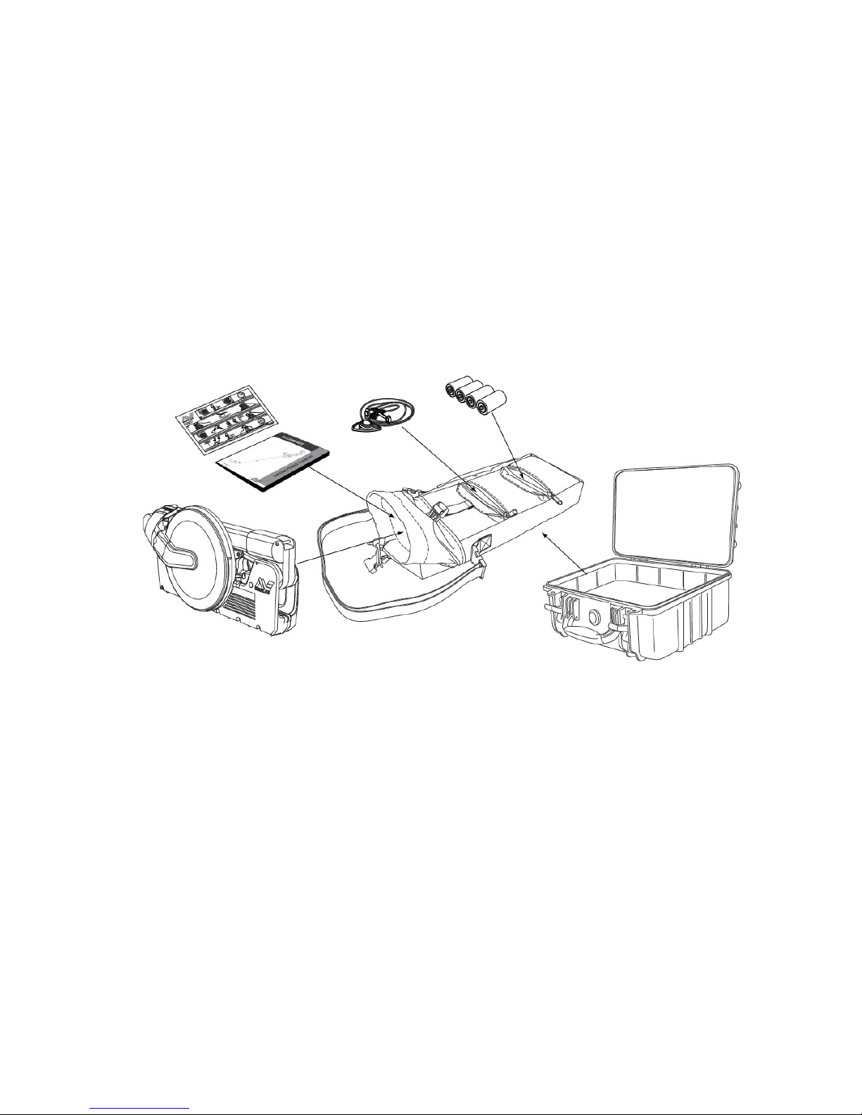
a. The detector set should be regularly checked to ensure all parts and accessories are
present and in good working order. The F3 COMPACT is supplied as a mine detecting set
comprising:
F3 COMPACT Detector 4901-0103 Operations Manual
5305-0111 Hard Case (optional) 4903-0047 Field Guide
3001-0064 Soft Carry Bag 8701-0022 Test Piece
4523-0027 Earset Speaker ON Four C-Cell Batteries
OR (Alkaline or Rechargeable)
4523-0025 Earset Speaker OFF
b. Whenever a detector is returned for servicing, mechanical and functional tests must be
completed to confirm and/or identify any faults.
c.
At the completion of any maintenance or repair procedure, ALL mechanical and
functional tests must be completed to confirm the detector is working correctly and no faults
remain.
d.
If a detector fails ANY of the mechanical or functional tests it must not be used in
demining operations.
Figure 1: Mine Detecting Set
Page 5
F3 COMPACT Service Manual
_______________________________________________________________________________________________________________________
5
2.1 Mechanical Testing
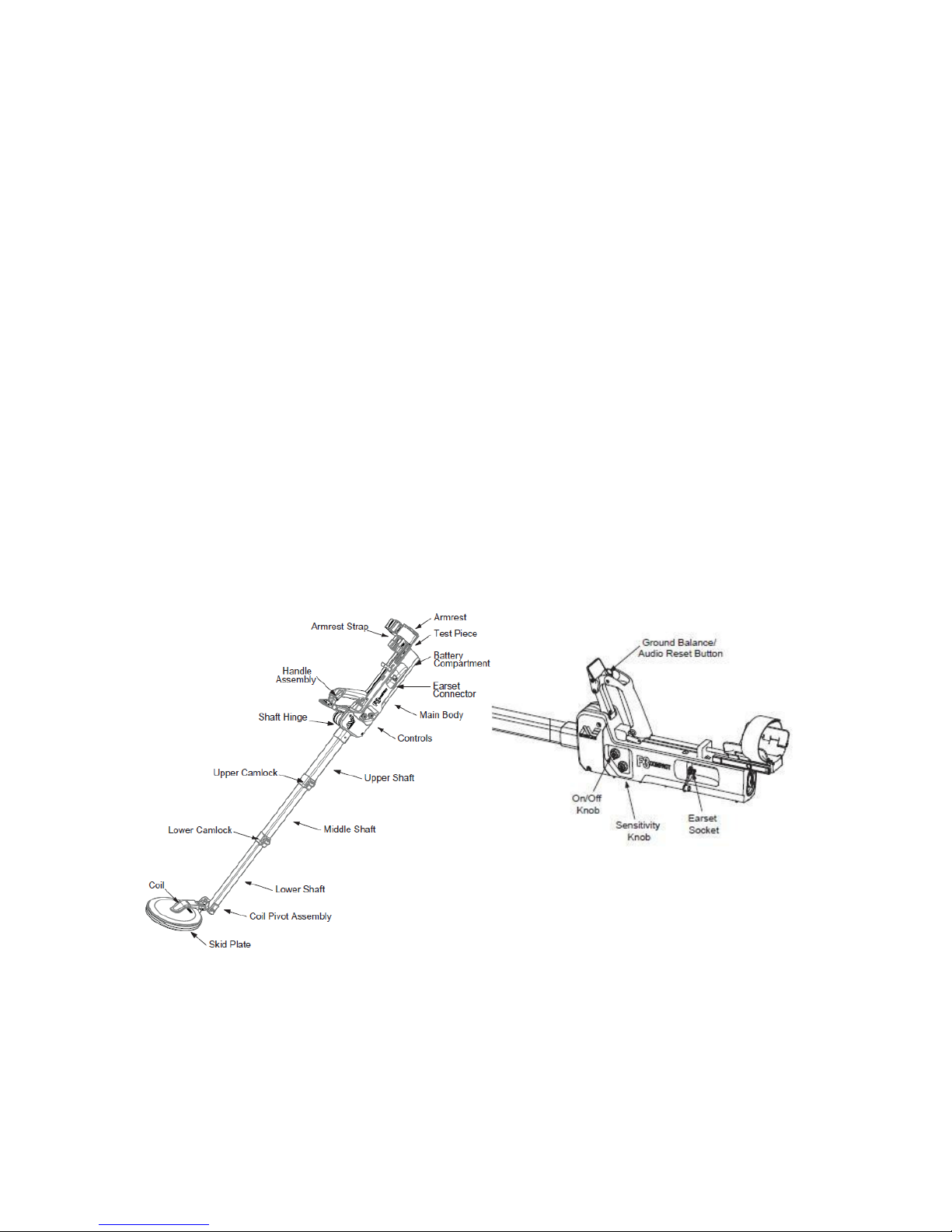
a. Confirm all parts and accessories are present and in good working order. Unpack the
detector and prepare for use. Figure 2 identifies the major components of the F3 COMPACT.
Mechanical testing and inspection includes checking:
• the detector for any obvious signs of damage,
• coil movement is smooth in both axes and holds its position without drooping,
• the skid plate is firmly attached and has no holes or cracks,
• shafts extend and retract smoothly and the camlocks hold the shafts firmly in location,
• the shaft hinge moves freely when the handle is down and locks into extended position
when the handle is up,
• the battery lid opens and locks, the battery lid tether is in good condition, and the battery
lid O-ring is clean and in good condition,
• the handle slides up and down freely locking into position,
• the armrest extends and retracts smoothly,
• the armrest strap is in good condition,
• the earset dust caps are in good condition, and
• sensitivity and On/Off knobs do not turn unless lifted and rotated and then spring back
into the locked position when released.
b. The detector must pass all mechanical tests and checks to be considered acceptable for
operational use.
Figure 2: F3 COMPACT Major Components
Page 6

F3 COMPACT Service Manual
_______________________________________________________________________________________________________________________
6
2.2 Functional Testing
a. Functional testing is used to confirm the serviceability of an F3 COMPACT before it is
returned to the field for use and whenever doubt exists about its serviceability. The F3 COMPACT
must pass all tests to be considered serviceable and ready for use. Whenever a line replaceable
unit is replaced or a repair is conducted, all functional testing must be completed.
b. Functional testing requires a ground balance test piece. The ground balance test piece
simulates mineralised ground which results in an alarm from the detector. A mineralised “hot”
rock or adequate amounts of local mineralised soil is suitable. Alternatively, a ceramic floor tile
or clay roof tile may be suitable for use as a ground balance test piece.
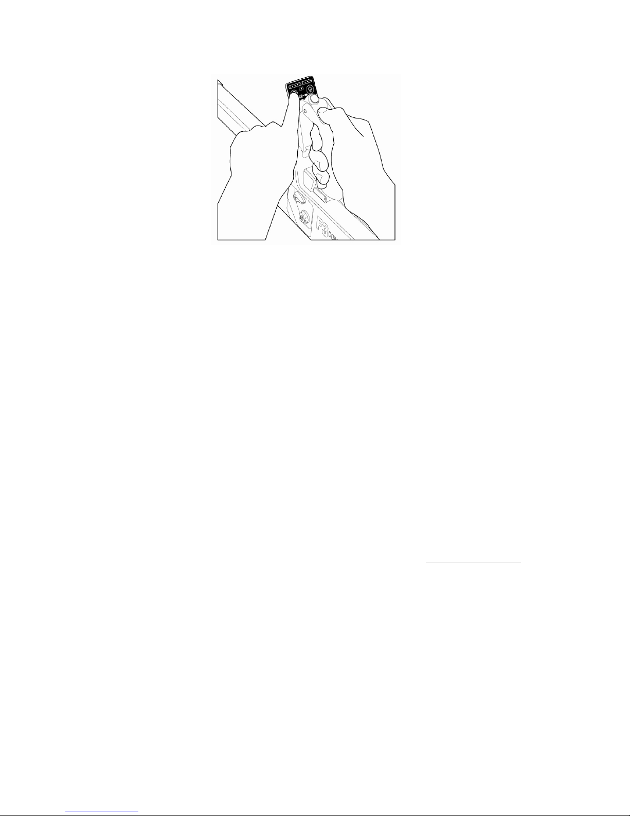
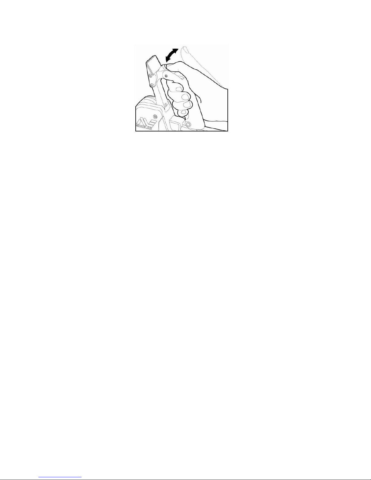
c. The Switch On Test. The switch on test checks that power is correctly supplied to the F3
COMPACT and internal diagnostics discover no system fault. The test is conducted as follows:
• Prepare the detector for use.
• Hold the coil at least 600mm (24in) away from the ground and any metal objects.
• Ensure the sensitivity knob is set to the default position 4.
• Switch on.
• Ensure that four or five rising tones occur over approximately 12 seconds. A steady
threshold tone should be heard a few seconds after the rising tones finish.
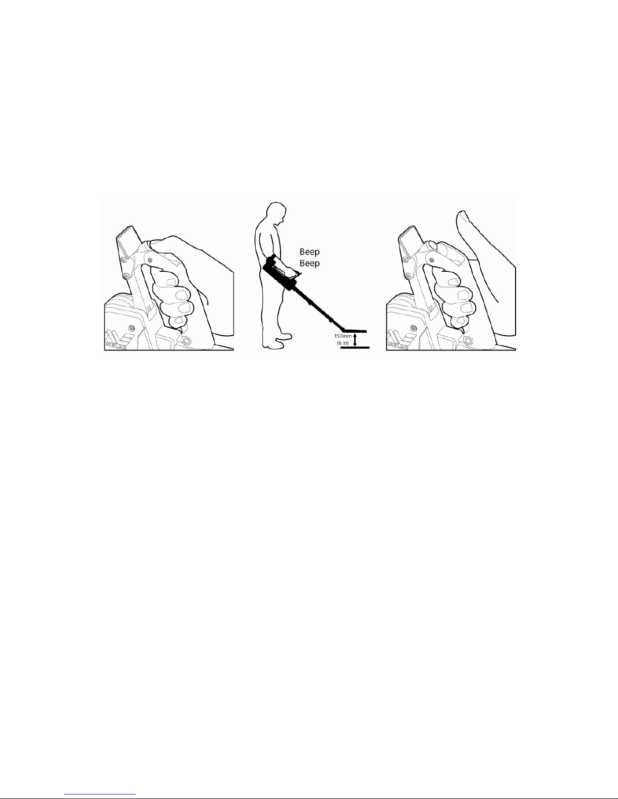
d. Noise Cancel Test. The noise cancel test ensures the F3 COMPACT successfully
completes the noise cancel procedure required whenever local electrical interference is present.
The test is conducted as follows:
• Hold the coil stationary and at least 600mm (24 in) off the ground and away from any
metal objects during the test.
• Press and immediately release the Noise Cancel button. (Figure 4)
Figure 3: Switch On
Page 7
F3 COMPACT Service Manual
_______________________________________________________________________________________________________________________
7
Note
The coil should not be moved nor should metallic objects be brought near the coil during this
procedure.
• If functioning correctly, the noise cancelling procedure will commence with two single
beeps followed by 45 seconds of sharp double beeps and finish with four single beeps.
• During the 45 seconds the F3 COMPACT scans the environment searching for the source
of any electrical interference. Once detected, the detector will automatically select a
different operating frequency to eliminate or reduce the interference.
e. Audio Reset Test. This test confirms the audio reset button (also the ground balance
button) and the associated wiring and circuitry operates correctly. The objective is to ensure the
threshold tone returns to its correct volume if altered from its steady state. The test is
conducted as follows:
• Hold the coil at least 600mm (24in) off the ground and away from any metallic objects.
• Induce a threshold tone change in volume by slowly moving the coil toward a metal
object and once the threshold tone increases in volume hold the detector stationary.
• Once the threshold tone has increased in volume, press and immediately release the
green audio reset button. (Figure 5)
Note
If the ground balance button is not immediately released the F3 COMPACT will commence the
Ground Balance procedure.
Figure 4: Noise Cancel
Page 8
F3 COMPACT Service Manual
_______________________________________________________________________________________________________________________
8
• Within two seconds the threshold tone should return to its correct level
f. Ground Balance Test. This test confirms the F3 COMPACT is capable of ground balancing
against mineralised ground. In doing so, it confirms the correct operation of the ground balance
button, coil and associated circuitry. The test is conducted as follows:
• Ensure hands and arms are free of metallic objects (watches, rings etc) and that no other
metallic objects are near the coil.
• Keep the detector stationary and away from ground or metal objects, press and hold the
ground balance button for five seconds then release the button.
Note
This action will cause the F3 COMPACT to delete the previously stored ground balance condition.
Unless this is done the detector will remember its last ground balance condition regardless of the
unit being switched off or the batteries removed.
• Slowly move the ground balance test piece from approximately 150mm (6in) above the
coil towards the centre of the coil and confirm that a rise in threshold tone occurs. This
confirms that the detector is detecting the mineralised content of the ground balance
test piece.
• Press down and hold the ground balance button whilst slowly moving the ground balance
test piece from approximately 150mm (6in) above the coil towards the centre of the coil
(and touching the coil). Then, move the ground balance test piece away from the centre
of the coil to a distance of 150mm (6in).
• Repeat this process until the ‘Ground Balance OK’ tone consisting of a short high-pitched
double beep occurs. This tone confirms the ground balance procedure has been
completed correctly.
• Release the ground balance button and confirm that a steady low volume threshold tone
remains.
Figure 5: Audio Reset
Page 9
F3 COMPACT Service Manual
_______________________________________________________________________________________________________________________
9
• Confirm the ground balance is correct by moving the ground balance test piece from
approximately 150mm (6in) above the coil towards the centre of the coil. If there is no
alarm from the ground balance test piece the ground balance procedure is functional.
Note
Where the ground balance test is conducted using local soil Figure 6 illustrates the procedure to
be followed.
Note
Successful ground balancing occurs within 5 to 10 seconds. Where the ground balance test piece
or local ground conditions are not sufficiently mineralised the ‘Ground Balance OK’ tones may
take up to 25 seconds to complete.
g. Earset Test. This test confirms the earset is operating correctly and is conducted as
follows:
• Plug the earset into the detector as shown in Figure 7.
• Switch on the detector and confirm the threshold tone is audible using the earset.
• If an earset speaker On (4523-0027) is being tested check that the tones can also be
heard from the detector loudspeaker.
• If an earset speaker Off (4523-0025), identified by green band on the earset cable near
the plug, is being tested check that tones can only be heard in the earset and not the
detector loudspeaker.
Figure 6: Ground Balance
Page 10
F3 COMPACT Service Manual
_______________________________________________________________________________________________________________________
10
h. LED Test. This test confirms the visual indicator (lights) can be enabled and operate
correctly. To conduct the test:
• Turn on the detector.
• Pass the coil over a metal object and check no LEDs are turned on.
• Press and release the LED button and check that a single LED is turned on when no metal
objects are near the coil.
• Pass the coil over a metal object and check that an increasing number of LEDs illuminate
as the target volume increases.
• Check that pressing and releasing the LED button toggles the LEDs on and off.
i. Battery Level Test. This test ensures that battery level indicator is operational, and is
conducted as follows:
• Turn the detector on.
• Press and hold the noise cancel button then press and release the LED button and then
release the noise cancel button.
• Confirm a series of LEDs illuminate indicating the level of battery power remaining.
• After three seconds the battery level indicator will extinguish and normal operation will
resume.
j. Test Piece Test. This test should be conducted in an environment that is free from
electrical interference and an earset must be connected. The test is conducted as follows:
• Ensure hands and arms are free of metallic objects (watches, rings etc) and that no other
metallic objects are near the coil.
• Set the sensitivity control to the default position 4 then switch on the F3 COMPACT and
confirm a steady threshold tone is present.
Figure 7: Connecting the Earset
Page 11

F3 COMPACT Service Manual
_______________________________________________________________________________________________________________________
11
Note
Maximum sensitivity is only available 30 seconds after the threshold tone is heard. Do not test
the F3 COMPACT with the test piece until 30 seconds after the threshold tone is heard.
• Hold the test piece above the middle of the coil with the rounded end (containing
metallic target) away from the coil.
• Move the test piece towards the centre of the coil until it lightly touches the coil then
move it sideways off the coil.
Figure 8: Test Piece Procedure
• Confirm a faint but clear response (change in threshold tone and pitch) is heard.
• If the test piece is not heard conduct an audio reset and repeat the test.
Note
The test piece test can only be conducted with the sensitivity control in the green position
(Sensitivity No 4). When the sensitivity control is not set to the green position it is the
responsibility of the user to provide an appropriate target with which to confirm the sensitivity of
the detector satisfies operational requirements.
k. Sensitivity Control Test. This test confirms the sensitivity control allows the operator to
make adjustments to the sensitivity of the F3 COMPACT. The test is conducted as follows:
• Set the sensitivity to the default position 4.
• Turn on the detector.
• Conduct the test piece test (refer to Section 2.2.j). Check that a faint but clear audio tone
is heard and that more than one LED illuminates.
• Decrease the sensitivity of the F3 COMPACT by rotating the sensitivity knob counter
clockwise to position 2. A single low pitched beep will be heard to prompt the operator
that the sensitivity is being decreased.
• Conduct the test piece test again and ensure no audio or LED response occurs.
• Move the sensitivity knob to position 4 and confirm a double beep occurs. This prompts
the operator that default sensitivity (position 4) has been selected.
Page 12

F3 COMPACT Service Manual
_______________________________________________________________________________________________________________________
12
• Rotate the sensitivity knob clockwise to position 6 and confirm that a single high pitched
beep is heard.
• Conduct the test piece test and confirm that a louder audio response and an increased
number of LEDs are illuminated when compared to the previous position 4 or 2.
Note
Regardless of minimum sensitivity at least one LED will remain illuminated providing an earset
speaker Off is not connected to the F3 COMPACT.
Page 13

F3 COMPACT Service Manual
_______________________________________________________________________________________________________________________
13
3. Disassembly & Reassembly Procedures
a. This section describes the procedures required to exchange line replaceable units.
Whenever a unit is replaced, mechanical and functional testing as described in Section 2 must be
completed.
b. It is recommended that the 3004-0055 F3 COMPACT service tool kit be used to conduct
disassembly and reassembly procedures. The tool kit contains the following:
• Pull-through for coil cable
• Flat blade screwdriver
• 3mm hex key driver
• 2.5mm hex key driver
• 2mm hex key driver
• T20 Torx driver
• 18mm spanner
• 13mm spanner
• 10mm spanner
• 3mm pin punch
• Screwdriver Pozidrive No 1
• Screwdriver Pozidrive No 2
• Tube Spanner 7/8
• Silicone grease
Page 14
F3 COMPACT Service Manual
_______________________________________________________________________________________________________________________
14
3.1 Opening the Detector Body
a. In order to conduct repairs and replace many of the parts of this detector, the first step
will often be to open the detector body. Many sections of this manual will refer back to this
section.
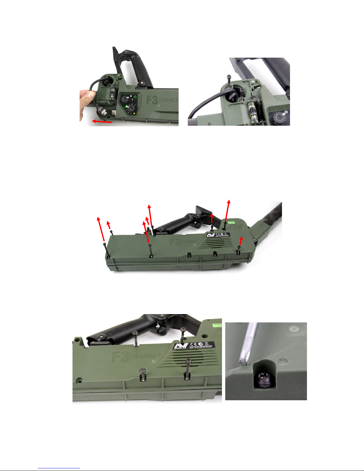
b. The following procedure outlines the steps involved in opening the detector body:
• Prepare a clean well lit workspace.
• Turn the detector off and remove the batteries.
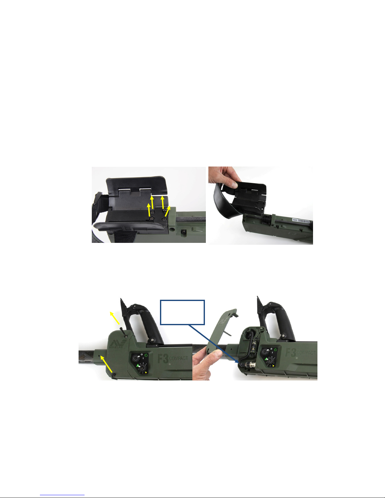
• Remove the four screws (12mm) from the top of the armrest and remove the armrest.
• Place the detector on its right side with the ON/OFF knob uppermost and remove the two
screws (45mm) that secure the hinge cover.
• Remove the hinge cover.
• Unscrew and disconnect the coil plug.
• Remove the two screws (35mm) from the shaft hinge.
Figure 9: Removing the Armrest
Coil
Connector
Figure 10: Removing Hinge Cover
Page 15
F3 COMPACT Service Manual
_______________________________________________________________________________________________________________________
15
• Turn the detector over onto its left side with speaker grill uppermost.
• Using the 3mm hex key driver, remove all eight screws from the detector body.
Note
There are four 35mm long screws and four 20mm long screws.
• Using a T20 Torx (star) driver unscrew all four screws (three 35mm and one 20mm) from
the right side of the detector.
Figure 12: Removing Eight Screws (Allen Key)
Figure 11: Disconnecting Coil Plug and Removing Screws
Figure 13: Removing Four Torx Screws
Page 16
F3 COMPACT Service Manual
_______________________________________________________________________________________________________________________
16
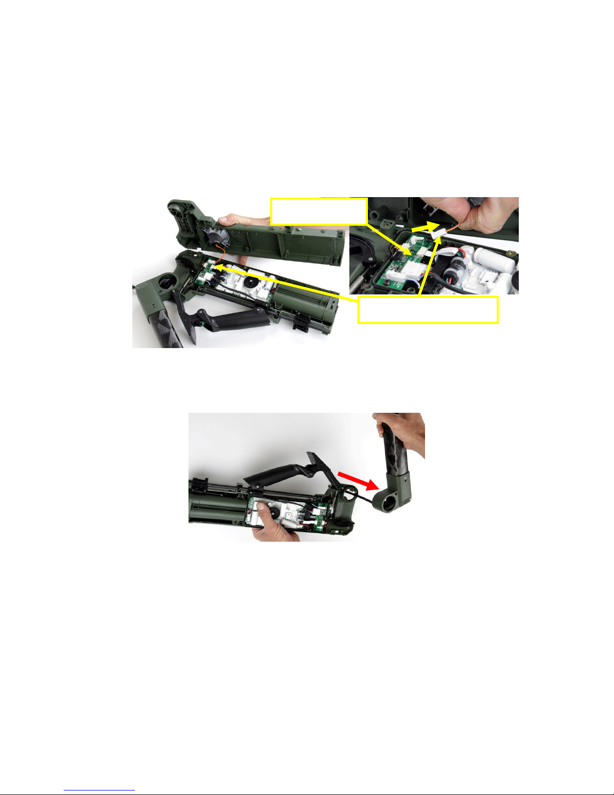
• Using fingers gently separate the left and right body halves. The battery end of the
detector will come away easily. The shaft end is held by two locating pins and will require
more force to separate.
• Gently lift the right side off the left body half taking care not to pull or stretch the speaker
cable and connector.
• Locate the speaker connector on the interface PCB and disconnect the speaker from the
interface PCB. Remove the right half of the detector body.
• Remove the upper shaft from the detector body taking care not to snag and damage the
coil cable and plug.
Interface PCB
Speaker Connector
Figure 14: Disconnecting Speaker Connector
Figure 15: Remov
ing Shafts
Page 17
F3 COMPACT Service Manual
_______________________________________________________________________________________________________________________
17
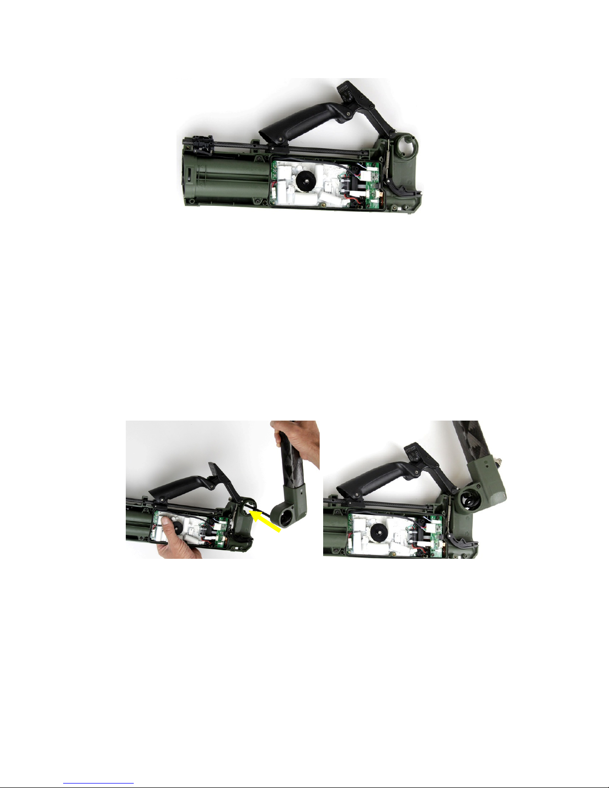
c. The body of the detector is now opened revealing the internal components which can
now be replaced as required.
3.2 Closing the Detector Body
a. The following procedure outlines the steps involved in closing and resealing the detector
body:
• Ensure all parts are present, in good working order and lay the detector body on its left
side.
• Thread the coil cable through the detector hinge and position the upper shaft into the
detector body.
• Carefully turn the detector body over so that it is on its right side. Check the coil
connector nut is tight.
• Attach the coil connector to the socket and tighten the coil connector as tight as possible
with fingers.
Figure 16: Open Detect
or Body
Figure 17: Threading Coil Cable and Attaching Shafts
Page 18
F3 COMPACT Service Manual
_______________________________________________________________________________________________________________________
18
• Fit the coil cable into the cable router and check that the loop of coil cable within the
shaft hinge is positioned so that it will not be trapped when the detector body is closed.
Refer to Figure 21.
• Fit the hinge cover but Do Not fit the two hinge cover screws. Turn the detector body
over so it is on its left side.
• Check the detector handle is correctly positioned on the detector as well as the armrest
slide. The rod detector slide must be positioned through the handle and armrest slide.
The holes in the rod detector slide must align with the holes in the detector body.
• Check that the latch hinge and spring latch hinge are correctly positioned into the left
side of the detector body with the latch connected to the spring.
Figure 18: Connecting Coil Cable and Removing Hinge Cover
Coil Connector Nut
Latch
Spring
Figure 19: Latch Hinge and Spring Latch Hinge
Rod Detector Slide passing
through Armrest Slide and Handle
Page 19
F3 COMPACT Service Manual
_______________________________________________________________________________________________________________________
19
Note
The hinge cover holds the latch hinge and spring latch hinge in place. When the hinge cover
is removed the spring may unintentionally disconnect from the latch.
• Ensure the battery lid is closed.
• Connect the speaker connector to the PCB connector. Check all other connectors and
cables are connected.
• Check the O-ring in the detector body is clean, lightly greased and correctly positioned.
• Check all internal cables and wires are correctly positioned and will not be trapped.
• The coil cable must be located within the shaft hinge so that it is not trapped or damaged
when the halves of the detector body are fitted together. In particular, the coil cable
must not be positioned above the hinge screw bosses.
Coil Cable
Must Not be
above these
areas
Figure 21: Coil Cable Position in Shaft Hinge
Speaker Connector
Figure 20: Connecting Speaker
Speaker Assembly
Page 20

F3 COMPACT Service Manual
_______________________________________________________________________________________________________________________
20
• Ease the two halves of the detector together. Align the detector body right side with the
locating pins either side of the shaft hinge.
• Check the latch hinge and spring latch hinge are in place and connected.
• Once the two sides of the detector are together check the handle, shafts and armrest
slide are correctly fitted. Carefully hold the detector together whilst turning the detector
over onto its right side with the hinge cover facing up.
• Remove the hinge cover to check the coil cable is not trapped within the shaft hinge.
• Check the latch hinge and spring latch hinge are still connected as shown in Figure 19.
• Refit the hinge cover.
• Insert the four screws (two 20mm and two 35mm) as indicated in Figure 22 but do not
fully tighten at this point.
• With the detector loosely held together check the handle slides up and down correctly.
Check the armrest slide also moves freely along the rod detector slide.
• Check the battery lid moves in and out and ensure the battery lid is closed.
• Starting with the two long (35mm) screws fit the four remaining screws into the right side
of the detector as indicated by the arrows in Figure 23.
• Tighten all eight screws.
Figure 22: Fitting Four Screws
Page 21

F3 COMPACT Service Manual
_______________________________________________________________________________________________________________________
21
• Identify the four Torx screws and check they all have O-rings fitted. Insert the four Torx
screws into the right side of the detector. The Torx screw positions have a Torx symbol
next to their screw holes. Insert the three long screws first.
• Check the detector assembly and test all moving parts.
• Place the detector on its right side. Remove the hinge cover then insert and tighten the
two screws (35mm) into the shaft hinge.
Figure 25: Fitting Screws into the Shaft Hinge
Figure 23: Fitting Four Screws
Torx Screw symbol
marks location of
O-ring
Figure 24: Fitting Torx Screws.
Page 22

F3 COMPACT Service Manual
_______________________________________________________________________________________________________________________
22
Note
Do not move the detector with the hinge cover removed as this may result in the spring
latch hinge and the latch hinge becoming disengaged.
• Confirm coil connector is tight and check the coil cable and the wiring loom are located
into the cable router.
• Check the latch and spring latch hinge are connected as shown in Figure 26. If the latch
and spring have become disconnected they must be reconnected. It is possible to
reattach the eyelet of the spring to the pin of the latch hinge through the opening under
the hinge cover. Alternately the detector body can be opened to reattach the spring to
the latch.
• Fit the hinge cover and make sure the protrusion on the underside of the hinge cover
engages into the slot on the detector body near the hinge. Fit the two screws (45mm)
into the hinge cover and tighten.
•
•
•
•
•
•
•
Figure 27: Fitting Hinge Cover
Cables held in
Cable Router
Spring Eyelet
located on pin of
Latch Hinge
Spring Latch
Hinge
Figure 26: Underneath Hinge Cover
Page 23

F3 COMPACT Service Manual
_______________________________________________________________________________________________________________________
23
• Reattach the armrest with four screws (12mm).
• Check all moving parts for correct operation.
• Insert batteries, turn on the detector then conduct mechanical & functional testing as
described in Section 2 Mechanical & Functional Testing.
3.3 Main Printed Circuit Board (PCB)
a. The main PCB of the F3 COMPACT is a line replaceable unit and this section of the manual
describes the procedure for its replacement. Figure 30 shows the main parts associated with the
main PCB.
b. 3004-0053 Main PCB Kit, is a service kit containing the main PCB and the associated parts,
when a replacement main PCB is required this part number should be ordered.
Note
Repairs to and disassembly of the main PCB are not detailed in this manual. Repairs to the
main PCB should only be conducted by authorised Minelab Engineers.
Figure 28: Attaching the Armrest
Toroid Screw
Cable 10 Way
Main
PCB
Cable 6 Way Ribbon
Speaker Connector
Interface PCB
Battery Connector
Figure 29: Detector Body and Main PCB
Page 24

F3 COMPACT Service Manual
_______________________________________________________________________________________________________________________
24
1 3004-0053 Main PCB Kit, contains all parts in this table.
2 0703-0208 Cover Toroid
3 0704-0009 Gasket Toroid
4 31-23040-980 Screw Toroid M3x40 skt
5 4005-0054 Spacer Toroid mid
6 4311-0080 Bracket Main PCB
7 CMINE 0672 Jumper 2 Way Quantity 3
8 67-50062 Cable 6 Way Ribbon 178mm
9 67-50104 Cable 10 way 50mm
3.3.1 Removing the Main PCB
a. To remove the main PCB, open the detector body as described in section 3.1 – Open the
Detector Body and:
• Remove the Nut (18mm) from the coil connector.
Figure 31: Opened Detector Body
4311
-
0080
67-50104
67-50062
4005
-
0054
0704
-
0009
0703-
0208
31-23040
-
980
Figure 30: Parts of the Main PCB
Table 1: Parts of Main PCB
Page 25

F3 COMPACT Service Manual
_______________________________________________________________________________________________________________________
25
• Unscrew the screw toroid from the main PCB, using a 2.5mm hex key driver.
• Disconnect the battery connector from the main PCB.
• Remove the two Screws (12mm) from the interface PCB.
• Disconnect the 10 way connector from the interface PCB (Figure 35).
Figure 33: Screw Toroid & Battery Connector
Battery Connector
Screw Toroid
Mounting
Screws
Interface PCB
Figure 34: Interface PCB
Figure 32: Remov
ing the Coil Connector Nut (18mm)
Page 26

F3 COMPACT Service Manual
_______________________________________________________________________________________________________________________
26
• Slide out the locking bails on the six way ribbon connector and disconnect the cable six
way ribbon.
• Slide the main PCB away from the battery assembly until the ends of the main PCB
disengage from the slots in the detector body near the battery compartment.
• Gently tilt the top side (near the detector handle) of the main PCB away from the housing
and lift the main PCB from the detector body.
b. The main PCB can now be replaced.
2
Figure 36: Lifting Main PCB Out of Detector
Figure 35: 10 Way Connector and Six Way Ribbon Cable
Cable
Six Way
Ribbon
10 way Connector
Page 27

F3 COMPACT Service Manual
_______________________________________________________________________________________________________________________
27
3.3.2 Main PCB Assembly
a. When the line replaceable unit 3004-0053 Main PCB Kit is supplied by Minelab no
assembly is required. However, in the event a main PCB is salvaged from one detector for use in
another, it is important to check for correct assembly before fitting the main PCB to the
detector. Check for correct assembly as follows:
• Check that the six way ribbon cable is connected to the main PCB.
• To connect the six way ribbon cable, separate the two halves of the PCB and open the
connector bail. Insert six way ribbon cable and close the connector locking bail.
• Check the spacer toroid mid is in place between the two halves of the PCB.
• Connect the two halves together and check the PCB interconnectors are aligned and fully
inserted.
• Connect the 10 way ribbon cable, ensuring that the key on the connector is aligned with
the slot on the PCB.
Figure 38: Fitting Bracket
• Fit the bracket main PCB.
• Check that three jumpers are connected in the correct positions on the main PCB. Refer
to Figure 39.
10 Way Ribbon Cable.
Bracket Main PCB.
Figure 37: Connecting Six Way Ribbon Cable
Spacer Toroid Mid.
Page 28

F3 COMPACT Service Manual
_______________________________________________________________________________________________________________________
28
b. The main PCB is now ready to install into the detector.
3.3.3 Installing the Main PCB.
a.
Having opened the detector body and removed the faulty main PCB, install a serviceable
main PCB as follows:
• Place the detector on its left side in a clean well lit area.
• Lower the main PCB into the detector, pushing the bottom side (away from the handle)
down and into place first. Gently position the main PCB flat inside the detector.
• Gently slide the main PCB rearward towards the battery compartment so that the ends of
the main PCB insert into the locating slots in the detector body.
• Position the coil connector ensuring the connector has a clean and correctly positioned
O-ring as shown in Figure 41.
• Fit the cable of the coil connector into the cable router as shown in Figure 41.
Figure 39: Three Jumpers on Main PCB
Figure 40: Fitting Main PCB
Page 29

F3 COMPACT Service Manual
_______________________________________________________________________________________________________________________
29
• Fit the screw toroid as shown in Figure 42.
• Lay the cable 10 way under the interface PCB. Take note of the connector key tab that
aligns with the slot in the interface PCB.
• Gently align and connect the connector 10 way.
Figure 41: Coil Connector
O-Ring in place on
Coil Connector
Cable of Coil
Connector fitted
into Cable R
outer
Alignment Key
Figure 43: Connector 10 Way
Figure 42: Screw Toroid
Page 30

F3 COMPACT Service Manual
_______________________________________________________________________________________________________________________
30
• Align the cable six way ribbon with its connector. Slide the connector locking bail
outwards to accept the cable six way ribbon.
• Insert the cable six way ribbon into the connector then push the locking bail to secure.
• Connect the battery connector to the main PCB.
• Make sure all connectors are firmly in place and all wires and cables are positioned so
that they will not cause obstruction or get damaged when the two halves of the main
body are fitted together.
• Fit the two screws (12mm) to the interface PCB.
Figure 45: Connecting Battery Connector
First Pull locking bail out to accept Cable
Push locking bail in
Figure 44: Connecting Six Way Ribbon Cable
Second insert Six Way Ribbon Cable
Figure 46: Interface PCB and Coil Connector Nut
Page 31

F3 COMPACT Service Manual
_______________________________________________________________________________________________________________________
31
• Fit the nut (18mm) to the coil connector and tighten.
b. Finish assembling the detector by closing the detector body, as described in Section 3.2 –
Closing the Detector Body
3.4 Coil
a. The coil is a line replaceable unit and Figure 47 illustrates the major parts of the coil.
3004-0044 Coil Kit, is a service kit containing the coil and associated parts. 3004-0045 Coil Pivot
Kit, is included within the 3004-0044 Coil Kit and is also available as a separate service kit. All
parts are available individually.
1 3004-0044 Coil Kit, Includes all items in this table
2 2003-0055 Skid Plate
3 3004-0045 Coil Pivot Kit, included parts marked yellow
4 30-29011-514 O Ring 25mm ID
5 4311-0074 Pivot Coil Yoke
6 4311-0086 Pivot Lower Shaft
7 4003-0123 Screw Nylon M6x29
8 4003-0116 Screw Nylon M6x14
9 4003-0121 Screw Thumb Nylon 1/4BSW
10 0703-0204 Cap Shaft
30-29011
-
514
4311
-
0074
4308
-
0030
4003
-
0123
4003
-
0121
4308
-
0031
2003
-
0055
4311
-
0086
0703
-
0204
Lower Shaft
4003
-
0116
Figure 47: Parts of the Coil
Page 32

F3 COMPACT Service Manual
_______________________________________________________________________________________________________________________
32
11 4308-0030 Pin Coil Pivot
12 4308-0031 Pin Coil Cable
3.4.1 Skid Plate Replacement
a. The skid plate is designed to protect the coil and may require replacement after long
periods of use. There is no requirement to remove the skid plate to clean inside during routine
maintenance or operation. To exchange the skid plate:
• Remove the skid plate using fingers to lever one side away from the coil. Place a match
stick in the opening or something soft that will not mark the coil or skid plate.
• Move around the circumference of the coil using fingers to lever the skid plate away from
the coil. Insert additional match sticks to stop the skid plate from re-attaching to the coil.
The skid plate can then be removed from the coil
Note
Do not use a knife, screwdriver or any other steel objects to remove the skid plate. This could
mark or damage the coil or skid plate.
• Re-attach the skid plate by positioning the skid plate underneath the coil and then
pressing it into position.
3.4.2 Removing the Coil
a. To remove the coil:
• Prepare a clean well lit area in which to work.
• Turn the detector off and remove the batteries.
• Place the detector on its right side and remove the two screws (45mm) that secure the
hinge cover.
• Remove the hinge cover.
Figure 48: Replacing the Skid Plate
Table 2: Coil Parts
Page 33

F3 COMPACT Service Manual
_______________________________________________________________________________________________________________________
33
• Unscrew and disconnect the coil connector.
• Remove the pin coil cable from the upper end of the upper shaft. Turn the pin clockwise
then pull to remove.
• Remove the two screws (Nylon 14mm) from the cap shaft on the lower shaft as indicated
in Figure 52.
Figure 50: Disconnecting Coil Connector
Figure 51: Removing Pin Coil Cable
Coil
Connector
Figure 49: Removing Hinge Cover
Figure 52: Removing Screws from Lower Shaft
Page 34

F3 COMPACT Service Manual
_______________________________________________________________________________________________________________________
34
• Insert a flat tip screwdriver into the slot underneath the cap shaft and lift and remove the
cap shaft.
• Slide the coil out and off the lower shaft, exposing the coil cable.
• Push the coil cable connector into the shaft hinge whilst gently pulling the coil cable out
of the end of the lower shaft. Once the coil connector has passed through the shaft hinge
it should slide out easily from the shafts. Do not force the coil cable or coil connector.
b. The coil can now be removed or replaced as required. To fit the coil to the detector refer
to section 3.4.6 - Fitting the Coil.
3.4.3 Coil Pivot.
a. The coil pivot is a line replaceable unit and Figure 55 illustrates the major parts. Each part
of the coil pivot can be ordered individually or as a 3004-0045 Coil Pivot Kit which includes all
parts shown in Table 3.
Figure 53: Sliding the Coil Off the Shaft
Figure 54: Coil Assembly
Figure 55: Coil Pivot Kit Parts
4003
-
0123
4311-0074
30-29011
-
514
4308
-
0030
4003-0116
0703
-
0204
4311-0086
4003
-
0121
Page 35

F3 COMPACT Service Manual
_______________________________________________________________________________________________________________________
35
1 3004-0045 Coil Pivot Kit, contains all items in this Table
2 30-29011-514 O-Ring 25mm ID x2
3 4311-0074 Pivot Coil Yoke
4 4311-0086 Pivot Shaft
5 4003-0123 Screw Nylon M6x29
6 4003-0121 Thumb Screw Nylon 1/4BSW
7 4308-0030 Pin Coil Pivot
8 4003-0116 Screw Nylon M6x14
9 0703-0204 Cap Shaft
3.4.4 Removing Coil Pivot
a. To remove the coil pivot, first remove the coil as described in section 3.4.2 - Removing
the Coil. Once completed:
• Remove the thumb screw and screw (Nylon M6x29).
Note
The two screws can be used to adjust the friction of the coil pivot movement.
• Push the pin coil pivot out with a pin punch or hex key driver and remove the pin coil
pivot.
Figure 57: Rem
oving Pin Coil Pivot
Figure 56: Removing Two Screws
Table 3: Coil Pivot Kit Parts
Page 36

F3 COMPACT Service Manual
_______________________________________________________________________________________________________________________
36
• Separate the pivot lower shaft from the pivot coil yoke. Gently feed the coil cable through
the pivot lower shaft removing the pivot shaft from the coil cable. Do not stretch the coil
cable.
• Pull the pivot coil yoke off the coil and carefully thread the coil cable through the pivot
coil yoke. If required remove the O-ring from the coil.
3.4.5 Fitting the Coil Pivot
a. To fit the coil pivot, firstly remove the coil from the detector as described in section
3.4.2 - Removing the Coil. Once completed:
• Fit the O-ring to the coil as shown in Figure 60.
Pivot Coil Yoke
Pivot Lower Shaft
Figure 5
8
: Removing Pivot
Lower
Shaft
Figure 59: Removing Pivot Coil Yoke
O-Ring
Page 37

F3 COMPACT Service Manual
_______________________________________________________________________________________________________________________
37
• Identify the section of coil cable closest to the coil and wind or unwind the coil cable to
achieve five turns. The five turns of cable will be located within the pivot with the pin coil
pivot passing through the centre.
• Feed the pivot coil yoke onto the coil cable and carefully move the pivot coil yoke along
the coil cable to the coil. Align and then push the pivot coil yoke into place on the coil.
Check the pivot coil yoke rotates through 90 deg with end stops.
• Feed the pivot shaft onto the coil cable. Align the coil cable with the five turns of cable
inside the pivot then press the pivot shaft onto the pivot coil yoke. Ensure the coil cable
retains the five turns of cable within the pivot.
O-Ring
5 Coils inside
Pivot
Figure 60: O-Ring and Coil Cable
Figure 61: Fitting Pivot Coil Yoke
Figure 62: Fitting Pivot Lower Shaft
Page 38

F3 COMPACT Service Manual
_______________________________________________________________________________________________________________________
38
• Push the pin coil pivot into the pivot coil yoke. The pin must travel up the centre of the
five turns of cable inside the pivot. If there is resistance to inserting the pin open the
pivot and try again. Do Not Use Excessive Force. Push the pin in with fingers and click
into place.
Note
The pin coil yoke must thread through five turns of the cable inside the pivot.
• Check the movement of the pivot in both directions.
• Fit the screw (Nylon M6x29) into the pivot coil yoke and then fit the thumb screw.
Tighten both screws until the movement of the coil starts to become firm.
Note
The thumb screw will adjust the friction of the coil tilt. The thumb screw must be tight enough to
stop the coil from drooping. The screw (Nylon M6x29) will adjust the friction of the coil rotation.
b. Fit the coil to the shaft then fit onto the detector as described in Section 3.4.6 - Fitting the
Coil.
Figure 63: Inserting Pin Coil Pivot
Figure 64: Adjusting Screws
Page 39

F3 COMPACT Service Manual
_______________________________________________________________________________________________________________________
39
3.4.6 Fitting the Coil
a. With practice and a pull through tool it is possible to fit the coil to the detector without
opening the detector body.
b. Open the detector body as described in Section 3.1 - Opening the Detector Body. Once
completed:
• Remove the shaft and coil from the detector. Section 3.4.2 - Removing the Coil
• Remove the cover shaft hinge from the shafts.
• Connect the coil cable pull-through to the coil connector. Alternatively, a piece of string
could be used to thread the coil cable into the shafts.
• Feed the coil cable pull-through into the coil end of the lower shaft and out through the
top (hinge end) of the upper shaft. Feed the coil cable until the coil connector is exposed.
• Insert the pin coil cable into the end of the upper shaft so that the pin engages into the
turns of the coil cable within the shaft. Turn the pin counter clockwise to lock it into
place.
Figure 66: Threading Coil Cable through Shafts
Figure 67: Fitting Pin Coil Cable and Cover Shaft Hinge
Figure 65: Removing Cover Shaft Hinge
Page 40

F3 COMPACT Service Manual
_______________________________________________________________________________________________________________________
40
• Fit the cover shaft hinge to the shaft and screw into place.
• Slide the coil into the end of the lower shaft. Fit the cap shaft then fit the two screws
(14mm Nylon).
• Thread the coil cable through the detector hinge and fit the shaft onto the detector
hinge.
• Connect the coil connector and close the detector body described in Section 3.2 - Closing
the Detector Body.
Figure 68: Fitting Coil to Lower Shaft
Figure 69: Fitting Shaft and Coil
Figure 70: Connecting Coil Cable and Cover
Coil Connector Nut
Page 41

F3 COMPACT Service Manual
_______________________________________________________________________________________________________________________
41
c. The coil has now been fitted to the detector. Check the assembly and all moving parts.
Insert batteries and then carry out mechanical & functional testing as described in Section 2 -
Mechanical & Functional Testing.
Page 42

F3 COMPACT Service Manual
_______________________________________________________________________________________________________________________
42
3.5 Shafts
a. The complete shaft assembly of the detector is a line replaceable unit and Figure 71
illustrates the major parts.
1 3004-0046 Shaft Kit, contains all items in this table
2 3004-0045 Coil Pivot Kit
3 3004-0047 Camlock Kit, contains 3 items marked green
4 8008-0062 Pressure Block Camlock
5 8008-0061 Camlock Lever
6 4308-0014 Pin Camlock Lever
7 4308-0018 Pin Lock Latch
8 4311-0073 Hinge Upper Shaft
9 8007-0065 Shaft Upper
10 8009-0011 Shaft Guide Middle
11 8008-0059 Camlock Body Upper
12 8007-0064 Shaft Middle
13 8009-0012 Shaft Guide Lower
14 8008-0060 Camlock Body Middle
15 8007-0063 Shaft Lower
16 0703-0202 Cover Shaft Hinge
17 31-03512-982 Screw 3.5x12 skt head
4308
-
0018
4311
-
0073
8007
-
0065
4308
-
0014
8009
-
0011
8008
-
0062
8008
-
0061
8007
-
0064
8009
-
0012
8008
-
0059
8008
-
0060
8007
-
0063
Figure 71: Shaft Parts
0703
-
0202
3004
-
0045
Page 43

F3 COMPACT Service Manual
_______________________________________________________________________________________________________________________
43
3.5.1 Replacing a Camlock
a. Camlock replacement can be achieved as follows:
• Open the camlock lever and using a pin punch and hammer drive the camlock pin out.
• Once the camlock pin has been removed the camlock pressure block can be removed and
replaced if needed.
Note
When the camlocks are closed they must hold the shafts firmly with no slippage. If the
camlock does not hold the shafts firmly in place then pressure blocks should be replaced.
• To reassemble the camlock, fit the pressure block to the camlock lever.
• Place the camlock lever with pressure block fitted into position within the camlock body
then press the camlock pin into place.
3.5.2 Removing the Shafts
a. To remove the shafts from the detector firstly open the detector body as described in
Section 3.1 – Opening the Detector Body. Once completed:
• Lift the shafts clear of the detector.
Figure 72: Removing Camlock Pin
Figure 73: Fitting Camlock Pin
Page 44

F3 COMPACT Service Manual
_______________________________________________________________________________________________________________________
44
• Remove the pin coil cable from the upper end of the upper shaft. Turn the pin coil cable
clock wise and then lift out.
• Remove the two nylon screws from the cap shaft on the lower shaft as indicated in Figure
76.
• Insert a flat tip screwdriver into the slot underneath the cap shaft and lift and remove the
cap shaft.
• Slide the coil out and off the lower shaft, exposing the coil cable. Feed the coil cable
connector into the upper shaft and pull the coil cable out of the end of the lower shaft.
Figure 76: Removing Screws from Lower Shaft
Figure 75: Removing Pin Coil Cable
Figure 74: Shaft and Coil removed from Detector
Page 45

F3 COMPACT Service Manual
_______________________________________________________________________________________________________________________
45
3.5.3 Fitting the Shafts
a. The detector body needs to be opened in order to fit the shafts to the detector, refer to
Section 3.1 – Opening the Detector Body.
b. The coil must be fitted to the shaft then the shaft fitted to the detector this process is
described in Section 3.4.6 - Fitting the Coil.
c. Assemble the detector as described in Section 3.2 - Closing the Detector Body.
d. Once the detector is fully assembled check the operation of all moving parts and test the
detector as described in Section 2 - Mechanical & Functional Testing.
Figure 77: Removing Coil Cable from Shafts
Figure 78: Detector Shaft and Coil
Page 46

F3 COMPACT Service Manual
_______________________________________________________________________________________________________________________
46
3.6 Handle
a. The handle assembly is a line replaceable unit and Figure 79 illustrates the major parts of
the handle.
1 3004-0050 Handle Kit, contains all items in this table.
2 0703-0207 Housing, Display
3 3014-0016 LED Display Assy
4 31-03512-982 Screw 3.5x12 skt head
5 4006-0038 Spring Latch Hinge
6 4006-0041 Spring Handle Detent
7 4308-0022 Pin Lock Handle Detent
8 4308-0023 Pin Handle Main Lower
9 4308-0024 Pin Handle Main Upper
10 4308-0026 Pin Spring Latch hinge
11 4311-0076 Hinge Handle Slide
12 4311-0079 Lock Handle Slide
13 8005-0067 Handle Main
14 8005-0068 Handle Forward Right
15 8005-0069 Handle Forward Left
16 9511-0134 Wiring Loom Handle
0703
-
0207
31-03512-982
3014-0016
8005
-
0068
8005
-
0069
9511
-
0134
4308
-
0024
4006-0038
8005
-
0067
4006-0041
4308
-
0022
4311-0076
4308-0026
Figure 79: Handle Parts
Table 5: Handle Parts
Page 47

F3 COMPACT Service Manual
_______________________________________________________________________________________________________________________
47
3.6.1 Removing the Handle
a. The detector body must first be opened to remove the handle as described in Section
3.1 - Opening the Detector Body. Once completed:
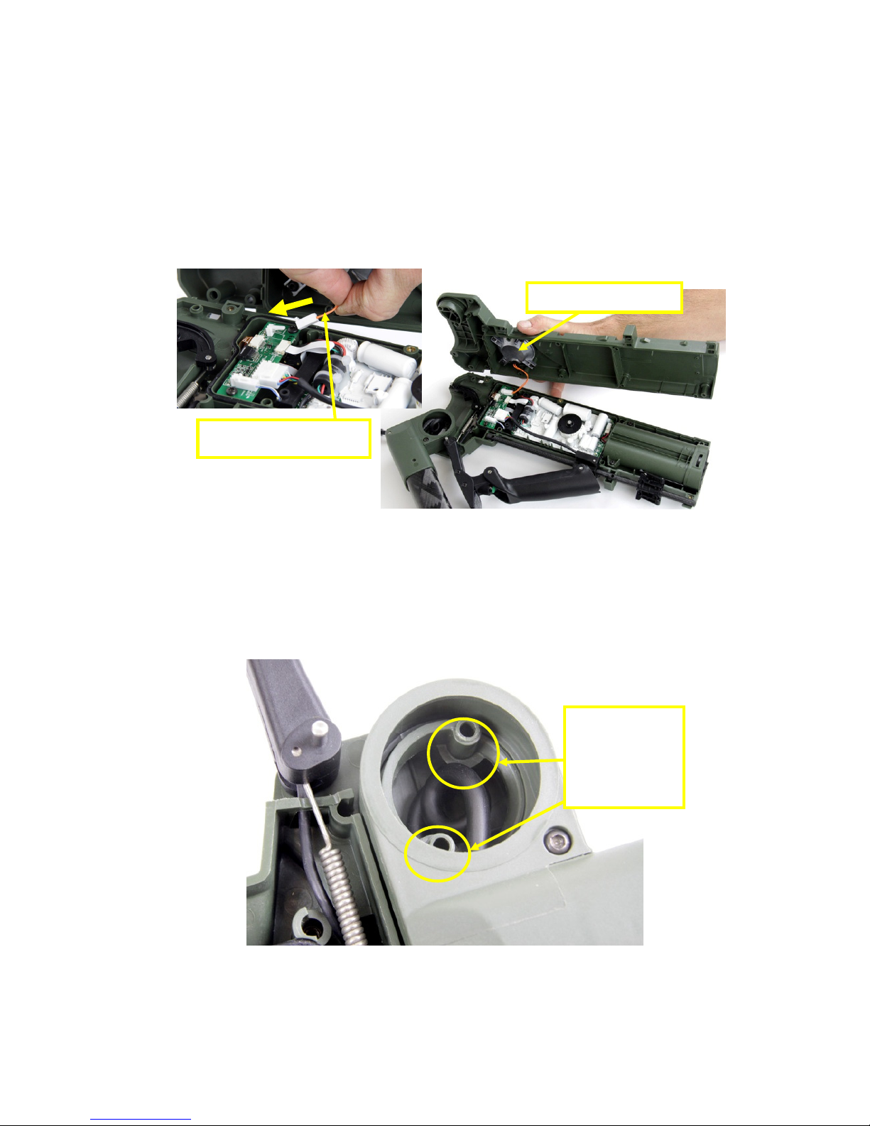
• Disconnect the wiring loom handle. Hold one side of the connector firm against the
detector body whilst gently pulling the other side.
• Disconnect the spring latch hinge from the latch hinge.
• Lift the handle off the pin handle pivot.
• Remove the rod handle slide from the handle.
• Pass the wiring loom handle through the top of the detector.
Pin Handle Pivot
Spring Latch Hinge
Latch Hinge
Handle
Rod Handle slide
Figure 81: Handle
Figure 82: Removi
ng Handle and Cable
Pin Handle Pivot
Figure 80: Disconnect Wiring Loom Handle
Page 48

F3 COMPACT Service Manual
_______________________________________________________________________________________________________________________
48
3.6.2 Fitting the Handle
a. To fit the handle the detector body must be opened as described in Section 3.1 - Opening
the Detector Body. Once completed:
• Thread the wiring loom handle into the detector body.
• Push the handle onto the pin handle pivot.
• Connect the spring latch hinge to the latch hinge.
• Feed the rod handle slide through the handle and into position.
• Connect the wiring loom handle and fit into the cable router.
Figure 83: Threading the Wiring Loom
Pin Handle Pivot
Latch
Spring
Figure 84: Latch Hinge and Spring Latch Hinge
Rod passing through Armrest Slide
and Handle
Page 49

F3 COMPACT Service Manual
_______________________________________________________________________________________________________________________
49
b. Assemble the detector and close the detector body as described in Section 3.2 - Closing
the Detector Body.
3.7 Armrest
a. The armrest is a line replaceable unit with or without slide as shown in Figure 86.
3.7.1 Replacing the Armrest
a. To replace the armrest:
• Prepare a clean well lit workspace.
• Turn the detector off and remove the batteries.
• Remove the four 12mm round head screws from the top of the armrest and remove the
armrest.
Figure 85: Correct Position of Wiring Loom Handle
3004
-
0048 Armrest Kit with Slide.
3004
-
0049 Armrest Kit
Figure 86: Armrest Service Kits
Page 50

F3 COMPACT Service Manual
_______________________________________________________________________________________________________________________
50
b. The armrest assembly can now be replaced as an assembly. If the armrest slide assembly
must also be replaced then the detector body must be opened as described in Section 3.1 -
Opening the Detector Body.
• Reattach the armrest and fit the four screws (12mm)
• Check the armrest folds in and out correctly and also check that the armrest slides
backward and forward.
3.8 Battery Compartment
a. The battery compartment and the battery lid are line replaceable units and available as
service kits which include associated parts as shown in Figure 88.
1 3004-0051 Battery Compartment Kit, contains all items.
2 3004-0052 Battery Lid Kit
3 31-03512-982 Screw 3.5x12 skt head
4 31-23001-927 Washer M3 Nylon
5 8005-0070 Tether Battery Lid
6 4309-0075 O-ring Battery Lid
Figure 87: Removing the Armrest
8005
-
0070
Table 6: Battery Compartment
3004-0052 Battery Lid Kit
Armrest Slide
3004-0051 Battery Compartment Kit
4309
-
0075
Figure 88: Battery Service Kits
31-23001
-
927
31-03512
-
982
Page 51

F3 COMPACT Service Manual
_______________________________________________________________________________________________________________________
51
3.8.1 Battery Lid Replacement
a. Open the detector body as described in Section 3.1 - Opening the Detector Body. Once
completed:
Note
The battery lid can be replaced without opening the detector body if the tether is unscrewed from
the battery lid.
• Check the battery lid has an O-ring correctly in place. The O-ring must be clean and can
be lightly greased.
• Check the battery lid closes onto the battery compartment. Fit and close the battery lid.
b. Close the detector body as described in Section 3.2 - Closing the Detector Body.
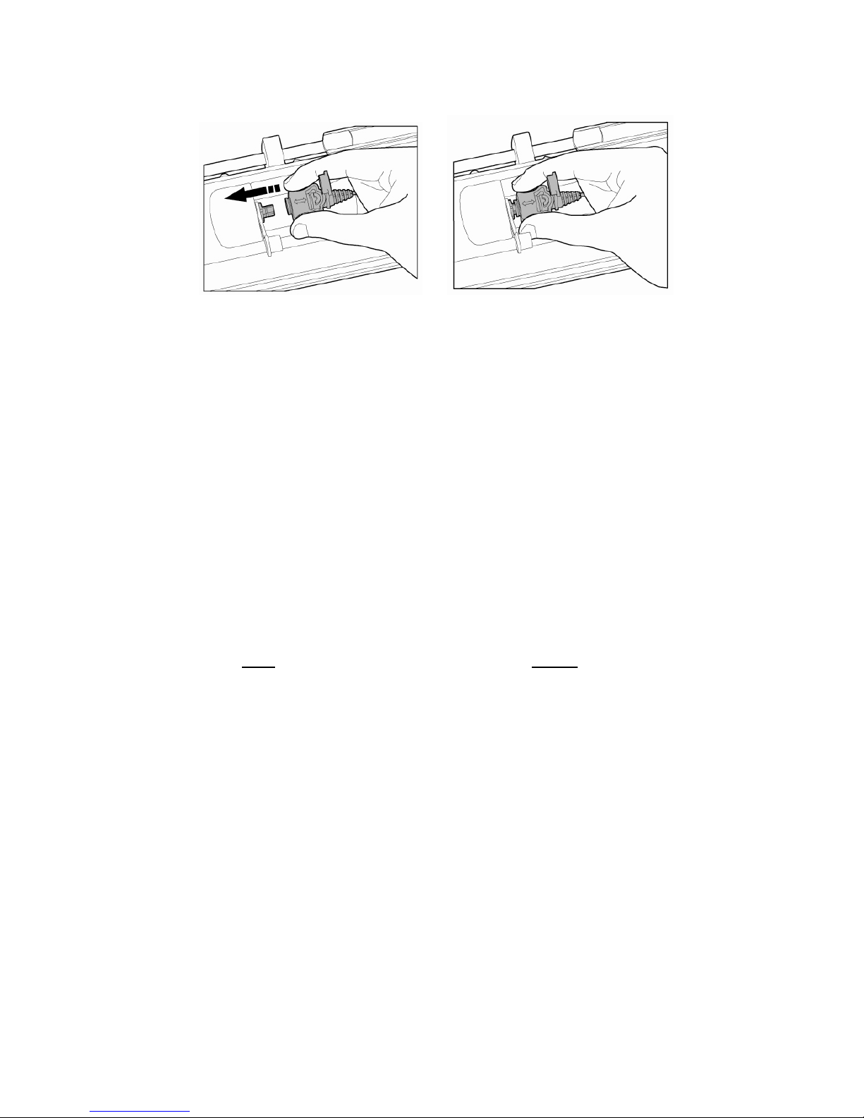
3.8.2 Battery Compartment Replacement
a. Open the detector body as described in Section 3.1 - Opening the Detector Body. Once
completed:
• Disconnect the battery connector.
• Remove the two screws (12mm) from the battery compartment.
• Slide the battery compartment rearward (away from the main PCB), threading the
battery connector out of the detector body.
Figure 89: Opened Detector Body
Battery Connector
Figure 90: Replacing Battery Compartment
Page 52

F3 COMPACT Service Manual
_______________________________________________________________________________________________________________________
52
• Refit the battery compartment by first feeding the battery connector through the hole in
the detector body.
• Slide the battery compartment into position.
• Connect the battery connector.
• Refit the two mounting screws (12mm).
• Close and lock the battery lid.
b. Reassemble the detector by closing the detector body as described in Section 3.2 -
Closing the Detector Body.
Page 53

F3 COMPACT Service Manual
_______________________________________________________________________________________________________________________
53
3.9 Detector Body
a. The detector body is not a line replaceable unit. The following assemblies within the
detector body are line replaceable units and are available as service kits:
• 3004-0054 Switches kit
• 3004-0056 Wiring Loom Handle Socket Kit
• 3004-0057 Speaker Kit
• 3004-0058 Wiring Loom Earset kit
b. All parts are available individually as spare parts.
3.9.1 Control Switches Replacement
a. The control switches are a line replaceable unit and are available as a service kit, 30040054 Switches Kit which includes all associated parts. Figure 91 illustrates all parts.
1 3004-0054 Switches Kit, includes all parts in this table
2 31-23006-989 Screw M3x6 skt csk
3 4005-0096 Bush Knob Lift and Turn
4 4006-0047 Spring Knob Lift and Turn
5 4305-0032 Knob Lift and Turn
6 5904-0177 Switches with Cable includes washer and nut
31-23006
-
989
4005
-
0096
4006
-
0047
4305
-
0032
Nut and Washer
5904
-
0177
Figure 91: Switches
Kit
Table 7: Switches Parts
Page 54

F3 COMPACT Service Manual
_______________________________________________________________________________________________________________________
54
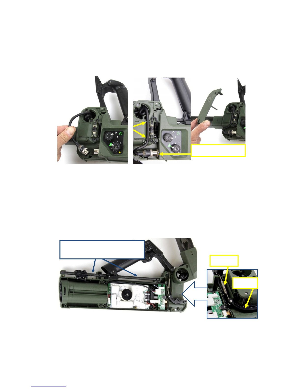
b. Open the detector body and remove the main PCB as described in Section 3.3.1 -
Removing the Main PCB. Once completed:
• Identify the six way ribbon cable from the control switches to the interface PCB.
• Open the locking bail of the connector on the interface PCB, disconnect the six way
ribbon cable.
• Lay the detector body on its side with the control knobs facing upwards. Set the controls
to off and setting 4.
• Using a 2mm hex key driver, undo the screws in the centre of each control knob and
remove the screw, bush, spring and knob from the switches.
• Take note of the orientation of the switches and the ribbon cable and use a 10mm
spanner to remove the nut and locking washer from both switches.
c. The control switches can now be removed and replaced.
Note
Use care handling the control switches and the flexible ribbon cable. These are internal
components and will be easily damaged if they are forced or misaligned.
Figure 92: Disconnecting Six Way Ribbon Cable
Figure 93: Removing Control Switch Knobs
Page 55

F3 COMPACT Service Manual
_______________________________________________________________________________________________________________________
55
Note
Do not use a soldering iron on the switches or the flexible ribbon cable.
• Check each control switch has a clean and lightly greased O-ring correctly positioned on
the mounting face.
• Carefully align the control switches and the flexible ribbon cable within the detector body
as illustrated in Figure 94.
• Insert the control switches into the detector body; fit the lock washer and 10mm nut.
• Fit the switch knob then the spring followed by the bush and screw to the control switch.
• Check the switch knobs move through their arc of movement with end stops.
• Identify the connector on the interface PCB that mates with the flexible ribbon cable of
the control switches. Open the connector locking bail (slide out). As shown in Figure 92.
• Insert the six way ribbon cable into the connector on the interface PCB then close the
locking bail on the connector.
d. Reassemble the detector by fitting the main PCB then closing the detector body as
described in Section 3.3.3 - Installing the Main PCB.
O-Ring
Figure 94: Control Switches
Page 56

F3 COMPACT Service Manual
_______________________________________________________________________________________________________________________
56
3.9.2 Speaker Replacement
a. The speaker is a line replaceable unit and available as a service kit, 3004-0057 Speaker
Kit. Figure 95 illustrates the major parts of the speaker.
1 3004-0057 Speaker Kit, contains all items in this table
2 0708-0011 Enclosure Speaker
3 30-05214-001 Circlip External 7mm
4 30-29011-011A O-Ring BS011 Silicone
5 30-39300-011 Tape Double Sided PVC 10x10x4.8mm
6 9511-0130 Wiring Loom and Speaker
7 30-29011-034 O-Ring BS034 Speaker
8 30-03512-982 Screw 3.5x12skt
b. Open the detector body as described in Section 3.1 - Opening the Detector Body. Once
completed:
• Remove the four screws (12mm) from the speaker assembly in the right side of the
detector body.
30-29011
-
034
30-05214
-
001
30-03512
-
982
30-29011
-
011
0708
-
0011
9511
-
0130
Figure 95: Speaker
Kit
Table 8: Speaker Parts
Page 57

F3 COMPACT Service Manual
_______________________________________________________________________________________________________________________
57
• Check speaker assembly is in good working order and the speaker cable is correctly
sealed into the speaker assembly and the E-Clip is fitted.
• Check the speaker O-ring is clean, lightly greased and correctly positioned in its channel in
the detector body.
• Position the speaker assembly and fit the four screws (12mm).
c. Assemble the detector as described in Section 3.2 - Closing the Detector Body.
3.9.3 Wiring Loom Earset Replacement
a. The wiring loom earset is a line replaceable unit and is available as a service kit, 30040058 Wiring Loom Earset Kit which includes associated parts. Figure 97 illustrates the major
parts of the wiring loom earset.
1 3004-0058 Wiring Loom Earset Kit, includes all items in this
table
2 9511-0158 Wiring Loom Earset
3 4309-0069 Dust Cap Earset Connector
4 4002-0053 Nut Earset Connector
b. Open the detector body and remove the main PCB as described in Section 3.1 - Opening
the Detector Body and 3.3.1 - Removing the Main PCB. Once completed:
Figure
96
: Replac
ing Speaker Assembly
Table 9: Wiring Loom Earset
4309
-
0069
4002
-
0053
9511
-0158
Figure 97: Wiring Loom Earset
Kit
Page 58

F3 COMPACT Service Manual
_______________________________________________________________________________________________________________________
58
Disconnect the wiring loom earset from the interface PCB.
• Unscrew the 13mm nut from the earset connector and remove the nut and the connector
dust cover.
c. The wiring loom earset can now be removed and replaced as required. The wiring loom
earset is fitted to the detector following the reverse order of the removal.
3.9.4 Wiring Loom Handle Socket Replacement
a. The wiring loom handle socket is a line replaceable unit and is available as a service kit,
3004-0056 Wiring loom Handle Socket Kit, which includes associated parts. Figure 98 illustrates
the major parts of wiring loom handle Socket.
1 3004-0056 Wiring Loom Handle Socket Kit, contains all
items in this table
2 9511-0136 Wiring Loom Handle Socket
3 30-29011-519 O-Ring BS012
4 30-05214-001 Circlip External 7mm
b. Open the detector body as described in Section 3.1 - Opening the Detector Body. Once
completed:
• Disconnect the wiring loom handle socket from the handle wiring loom.
• Disconnect the wiring loom handle socket from the interface PCB.
• Remove the E-Clip from the wiring loom handle socket at the entry point to the detector
body.
Table 10: Wiring Loom Handle Socket Kit
30-29011
-
519
30-05214
-
001
9511
-0136
Figure 98: Wiring Loom Handle Socket Kit
Page 59

F3 COMPACT Service Manual
_______________________________________________________________________________________________________________________
59
c. The wiring loom handle socket can now be removed and replaced. To fit the wiring loom
handle socket follow the removal instruction above in reverse order. Then assemble the
detector as described in Section 3.2 Closing the Detector Body.
3.9.5 Detector Body Parts
This section of the manual describes the parts of the F3 COMPACT detector in the body of the
detector that are not covered by the range of service kits, figures 100 to 103 illustrate these
parts
Wiring Loom Handle Socket
Connector to Interface PCB
E-Clip
Figure 99: Wiring Loom Handle Socket
0703
-
0203
31-24045
-
982
Screw M4x45
2703
-
0040
0304
-
0027
31-24035
-
982
Screw M4x35
0703
-
0205
Figure 100: Detector left side
Page 60

F3 COMPACT Service Manual
_______________________________________________________________________________________________________________________
60
31-24020
-
982
Screw M4x20mm
31-24035
-
982
Screw M4X35
2705
-
0061
30-43000
-
001
4003
-
0118
Screw M4x20 Torx
4003
-
0119
Screw M4x35 Torx
0703
-
0206
4309
-
0068
4007
-
0009
4308
-
0027
5904
-
0176
F
igure 102: Detector right side
Figure 103: Detector body
Figure 101: Detector right side
Page 61

F3 COMPACT Service Manual
_______________________________________________________________________________________________________________________
61
1 0703
-
0203
Hinge Cover
2 31-24045
-
982 Screw M4x45skt head
3 0703
-
0205
Chassis Left (switches side)
4 0703
-
0206
Chassis Ri
ght (speaker side)
5 0304
-
0027
Rod Handle Slide
6 4309
-
0068
Seal Detector Body
7 4007
-
0009
Latch Hinge
8 4308
-
0027
Pin Handle Pivot
9 5904
-
0176
Pin Handle Pivot
10 2703
-
0040
Decal Switches
11 2705
-
0061
Decal Compliance
12 2705
-
0025
Decal Serial Num
ber
13 30-43000
-
001 Vent Gore
14 31-24020
-
982 Screw M4x20 skt head
15 31-24035
-
982 Screw M4x35 skt head
16 4003
-
0118
Screw M4x20 Torx with seal
17 4003
-
0119
Screw M4x35 Torx with seal
Table 11: Detector body parts
Page 62

F3 COMPACT Service Manual
_______________________________________________________________________________________________________________________
62
4 Fault Finding Procedures
4.1 Introduction
a. A functional test failure can generally be repaired by replacing one or all of the line
replaceable units.
b. The F3 COMPACT is designed so that line replaceable units can be exchanged between
detectors without the need to calibrate. This means that where spare parts are not available
and more than one detector is faulty, then parts from one detector can be used to make another
serviceable. For example, if detector # 1 has an unserviceable coil and detector # 2 has an
unserviceable battery compartment, then the coil from detector # 2 can replace the coil on
detector # 1 thereby producing a serviceable detector.
4.2 Trouble Shooting Table
a. The following table identifies a number of faults and provides recommended solutions.
The suggested solutions should be investigated in the order they are listed.
Problem Recommended Solutions
Detector will not switch
on
● check batteries are installed correctly
● replace batteries with fresh batteries
● replace battery compartment
● replace main PCB
Detector will not switch
off
● remove batteries
● replace Main PCB
After switching on the
detector makes no
sound from speaker
● check for tone using the earset, turn LEDs on
● if there is tone through earset – replace the speaker
● if there is no tone through earset – replace main PCB
Threshold Tone is too
loud
● ensure area is free from local electromagnetic interference
● conduct Audio Reset
● conduct Noise Cancel
● check coil plug is tight
● replace coil
● replace main PCB
On switch on, the “Coil
Fault” tone occurs - “low
pitched double tone
every five seconds”
● check the coil plug is firmly secured
● inspect coil cable for damage – if no damage replace main
PCB
● if damaged replace with new coil
On switch on, the
“Equipment Fault” tone
occurs – “low pitched
slow oscillating tone
(ee-aww, ee-aww)
● turn off then on
● replace the switches
● replace main PCB
After working in hot
conditions, detector
makes a loud noise
● conduct Audio Reset
● check coil plug is tight
● replace coil
● replace main PCB
Page 63

F3 COMPACT Service Manual
_______________________________________________________________________________________________________________________
63
Ground Balance does
not work
● replace handle
● replace coil
● replace main PCB
Noise Cancel does not
work
(no Noise Cancel tones
emitted)
Note: Noise Cancel may not completely remove the effects of
interference if the source is powerful or in close proximity
● repeat Noise Cancel
● replace handle
● replace main PCB
Audio Reset does not
work
● repeat Noise Cancel
● replace handle
LEDs do not illuminate ● remove earset
● press LED button
● replace handle
● replace main PCB
Cannot hear the Test
Piece
● ensure detector has been switched on for 30 secs before
conducting the test
● fit and use an earset
● set sensitivity switch to default 4
● conduct Audio Reset
● conduct Noise Cancel
● ensure coil plug is firmly connected
● replace main PCB
● replace coil
Start Up tones keep
repeating
● insert new batteries
● replace battery compartment
● replace main PCB
Earset does not work ● replace earset
● replace wiring loom earset
Hinge will not lock shaft
extended
● push the handle up
● reconnect the spring latch hinge to the latch hinge
Armrest will not move ● replace armrest with slide
Coil does not remain in
place (floppy)
● replace coil pivot kit
Water found inside
battery pack
● clean battery lid and apply silicone grease to battery lid O-
ring
Camlocks will not stop
shafts from collapsing
● replace camlock kit
Battery Lid will not close ● remove and clean O-ring
● replace swollen batteries if applicable
oOo
 Loading...