

Page 1

The Minelab
B
Eureka Gold
L
A
U
N
A
M
N
O
I
T
C
U
R
T
S
N
I
MINELA
Page 2

WARNING
THIS DOCUMENT CONT AINS
MINELAB ELECTRONICS PTY L TD
LIMITED RIGHTS TECHNICAL DA T A, OR
RESTRICTED RIGHTS DATA, OR BOTH.
© Minelab Electronics Pty Ltd
This work is copyright. Ap art from any use
as permitted under the Copyright Act 1968,
no part may be reproduced by any process
without written permission from
Minelab Electronics Pty Ltd,
1 18 Hayward A venue,
Torrensville SA 5031, Australia.
4901-0046-1.1 January 2003
Page 3

The Minelab Eureka GoldPage 2
Minelab Eureka Gold
Instruction Manual
CONTENTS
Page
1. Introduction.............................................................................4
2. List of Parts .............................................................................5
3. Assembling the Detector ....................................................... 6
3.1 Armrest/Upper Shaft Assembly ................................................. 6
3.2 Lower Shaft Assembly ..............................................................6
3.3 Completing the Shaft Assembly................................................7
3.4 Shaft Mount ...............................................................................7
3.5 Rear Shaft Mount ......................................................................8
3.6 Hipmounting/Chestmount .........................................................9
4. Batteries ................................................................................ 10
4.1 Installation of NiMH Battery Pack ............................................10
4.2 Installation of Alkaline Batteries ............................................... 11
4.3 Low Battery Warning and NiMH Recharging.............................12
4.4 Using your NiMH Chargers........................................................12
5. The Eureka Gold Controls ..................................................13
5.1 V olume Control........................................................................13
5.2 Threshold Control ..................................................................13
5.3 Sensitivity Control ..................................................................15
5.4 Frequency Switch ...................................................................16
5.5 Signal Switch ..........................................................................16
5.6 Balance Switch .......................................................................17
5.7 Mode Switch ........................................................................... 17
5.8 T one...........................................................................................18
5.9 Headphones..............................................................................18
5.9 Coils..........................................................................................19
Page 4

Page 4 The Minelab Eureka Gold
6. Quickstart Operating Instructions......................................20
6.1 Best Setup Positions.................................................................21
7. Detector Sounds ..................................................................22
8. Operating Instructions - Fundamentals .............................23
8.1 Operating the Eureka Gold........................................................23
8.2 Ground Balance.........................................................................24
9. Detecting Techniques .......................................................... 25
9.1 Sweeping...................................................................................26
9.2 Pinpointing the T arget................................................................27
9.3 Digging the T arget......................................................................28
9.4 Automatic Ground Balancing.....................................................29
10. Discrimination .......................................................................31
10.1 Discrimination of Iron T argerts ............................................... 31
10.2 Discriminating in ‘Hot’ Ground ................................................31
10.1 Discriminating within Holes ....................................................32
11. Prospecting Tips .................................................................. 33
1 1.1 Mineralisation and ‘Hot’ Rocks ................................................33
11.2 Clay Domes ............................................................................ 34
11.3 Charcoal ................................................................................. 34
1 1. 4 Gold Lore ................................................................................35
12. The Coil and Skidplate ......................................................... 36
13. Environmental Concerns ..................................................... 37
14. Care of the Detector ............................................................38
14.1 Trouble-shooting Guide ...........................................................40
15. Warranty and Service ........................................................... 41
16. Specifications .......................................................................42
17. FCC Compliance and EC Conformity Notes ...................... 43
18. Minelab Service Repair Form .............................................44
Page 5

Page 5 The Minelab Eureka Gold
1. Introduction
Congratulations on purchasing Minelab’s Eureka Gold prospecting
detector. The Eureka Gold can constantly and automatically adjust the
Ground Balance to keep it at the correct setting. This will ensure that the
detector is always operating to its optimum strength, reducing operator
fatigue and allowing more ground to be covered in a day’s detecting.
For sensitivity to a wide range of targets, the Eureka Gold has a choice of
three operating frequencies:
• 6.4 kHz
• 20 kHz
• 60 kHz
Further refinements include target detection with pitch variation, better
signal-to-noise ratio in the electronics, and a 10” (25cm) Elliptical
Double ‘D’ coil as standard equipment.
This manual has been arranged with QuickStart instruction for
inexperienced users. More detailed notes about assembling the detector ,
how its controls work and methods of detecting are also included and well
worth reading by all operators.
As always at Minelab Electronics, we strive to provide you with the best
metal detection equipment possible. With that in mind we present the
Eureka Gold - the best continuous wave prospecting detector available
today.
If you have any questions or comments we would like to hear from you.
Please contact your local authorised Minelab Dealer or write to us direct.
We wish you every success in your prospecting and treasure hunting.
Since there may be a range of options available in this detector
type, equipment may vary according to the model or country of
issue. Certain descriptions and illustrations may differ (in this
manual) from the exact model that you have purchased. In
addition, Minelab reserve the right to respond to ongoing
technical progress by introducing changes in design, equipment
and technical features at any time.
Page 6

Page 6 The Minelab Eureka Gold
2. List of Parts
The box in which the Eureka Gold is shipped should contain the following
items. When you first receive your Eureka Gold check that all these items
are in the box:
• Eureka Gold Control Box
• 10” (25cm) Elliptical Coil with Skidplate attached
• 2-Piece Shaft Assembly including fibreglass lower shaft
• Aluminium 2-Piece Armrest (including nuts and bolts)
• Control Box Rear-mounting Bracket
• NiMH Battery Pack
• Mains power NiMH Battery Charger
• Neoprene Armrest Cover
• 2 Piece Armrest Strap
• Velcro Straps (2)
• Teardrop Washers
• Warranty Card
• User Manual
• Detector Stand
Please enter the required details on your warranty card and mail it to Minelab
Electronics Pty Ltd. It is extremely important that we receive your warranty
card within 14 days of date of purchase to register your new detector on
our warranty file.
The following accessories are also available to further improve your
detector:
• 12v NiMH Battery Vehicle Charger
• 11” Round Double ‘D’ Coil
• 15” Spider Double ‘D’ Coil
• Hipmount Bag
• Alkaline Battery pack
• Padded Cordura Detector Transport Bag
• Minelab Cap
• Minelab Polo shirt
• Minelab Jacket
Page 7
Page 7 The Minelab Eureka Gold
6
4
12
5
7
11
2
4
6
10
9
11
P0588-A
19
3
12
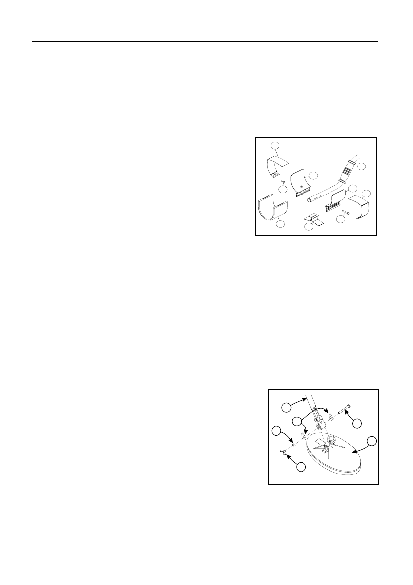
3. Assembling the Detector
Please follow these instructions to assemble the Eureka Gold. Refer to
the drawings to identify parts and how they are positioned. Please contact
your Minelab dealer for further instructions should any difficulties arise.
3.1 Armrest/Upper Shaft Assembly
a) Place the two armrest halves (4) on either
side of the upper shaft (2) and ensure that
the bolt hole is aligned.
b) Slide the nylon bolts through the bolt holes
and screw the nylon wing nuts (12) onto
the bolts with a couple of turns (do not
tighten).
Figure 2 - Armrest/Upper
Shaft Assembly
c) Slide the detector stand (7) into the
runners of the armrest (4) and tighten the nylon wing nuts by hand.
d) Attach the armrest straps (6) using the press studs on both sides of
the armrest.
P0570-A
e) Push the armrest straps through the slots in the armrest cover (5) and
push the cover over the armrest.
3.2 Lower Shaft Assembly
a) Remove the tape on the lower fibreglass tube
(3) that is holding the black teardrop washers
(10) in place.
Note: Ensure the washers do not fall out after
removing the tape.
b) Remove the black nylon wing nut (12), and
bolt (11) from the coil (9).
Figure 3 - The Coil and
Lower Shaft Assembly
Page 8
Page 8 The Minelab Eureka Gold
c) With the teardrop washers in place, push the lower tube (3) into the
coil bracket so that the holes line up.
Note: Ensure that the black nylon spring clip near the top of the fibreglass
tube is pointing toward the rear of the coil.
d) Push the black nylon bolt (11) through the holes in the bracket on the
coil from the cable entry side, put on the spacer (19) and tighten the
wing nut (12) by hand.
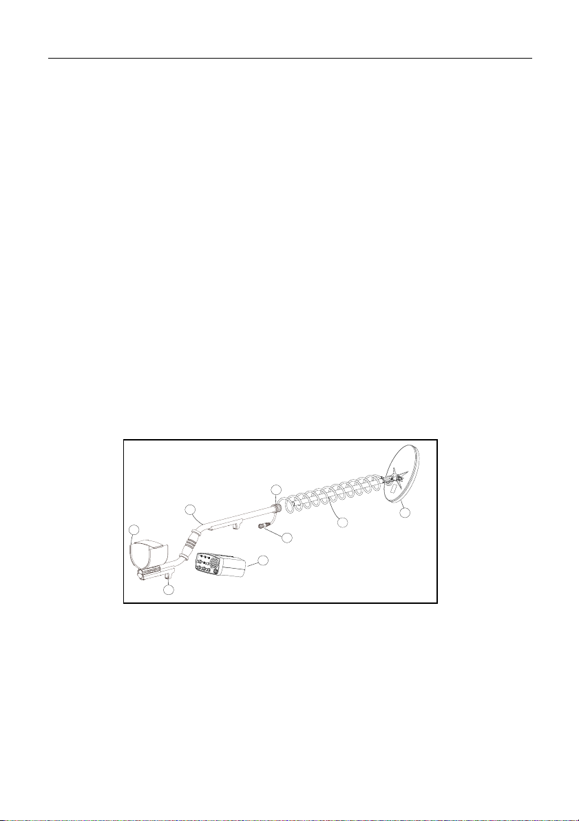
3.3 Completing the Shaft Assembly
a) Slide the lower shaft assembly (3) into the Aluminium upper shaf t (2).
Note: The black plastic locking nut (18) may need to be loosened to
position the lower shaft assembly correctly.
b) Set the length of the shaft by locking the black nylon spring clip
into one of the holes provided, then tighten the plastic locking nut.
18
2
4
8
13
1
3
9
P0585-A
Figure 4 - Completing the Shaft Assembly
3.4 Shaft Mount
a) Position the control box so that the recess in the control box (1) is aligned
with the leading edge of the mounting clip (8). Push the
forward section of the control box upwards until the trigger ‘clicks’
indicating the control box is secured (see figure 5).
Page 9

Page 9 The Minelab Eureka Gold
8
2
1
P0572-A
13
8
14
b) Firmly wind between 17 and 20 turns of the cable around the shaft until
it reaches the control box.
Note: Leave enough slack at the bottom of the cable near the coil to adjust
the coil position without straining the coil cable.
c) Connect the coil connector (13) to the plug on the rear of the control
box (14).
d) Use VelcroTM tabs to secure cable in the
correct position on the shaft maintaining
slack at coil and control box.
Note: Weather Protection - The hipmount
bag is designed so that it can be used to
weatherproof your control box while detecting in
inclement weather. The new design allows the
Figure 5 - Mounting the
Control Box on the Shaft
hipmount bag to protect the control box while still on the shaft. The
control box is positioned into the hipmount bag with the slot for the
mounting bracket positioned at the back. The velcroed panel is then
wrapped across the top of the stem. The hipmount bag is available from
your supplier as an accessory item.
3.5 Rear Shaft Mount
The Eureka Gold provides the option of mounting
the control box at the rear of the shaft (2),
beneath the armrest.
In order to mount the control box (1) in this
position:
a) Loosen the nylon wing nut from the armrest
and remove the detector stand.
Figure 6 - Mounting the
Control Box to the Rear
of the Shaft
P0573-A
Page 10
Page 10 The Minelab Eureka Gold
b) Slide in the black plastic rear control box bracket (8).
c) Tighten the nylon wing nut on the armrest.
d) Clip the control box onto the rear mounting bracket (see figure 5).
e) Firmly wind the cable up the stem using the Velcro
TM
tabs to hold in
position.
f) Connect the coil connector (13) to the plug (14) on the rear of the control
box.
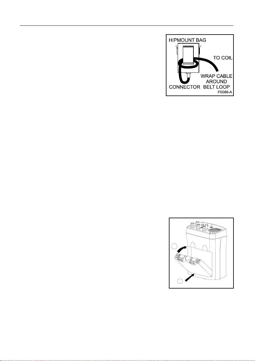
3.6 Hipmounting/Chestmount
Hipmounting is an alternative to mounting the detector on the shaft and
significantly reduces physical strain, enabling longer search time without
undue fatigue. A hipmount bag is available as an accessory item
for this purpose.
a) Check that there are charged batteries in the control box.
b) Place the control box into the hipmount bag with its control panel
facing outwards (see figure 7).
c) Place the hipmount bag in your preferred
working configuration. The hipmount bag can
be worn on the belt or over the shoulder.
Note: If mounting the hipmount bag on the chest,
a belt can be thread through the belt loop and
around the chest to hold the bag in position.
d) Wind about 5 turns of the cable around the
shaft. This will reduce the amount of excess
cable.
P0582-A
Figure 7 - Hipmounting
the Control Box
Page 11
Page 11 The Minelab Eureka Gold
B
A
P0586-A
Note: Leave enough slack at the bottom of the
cable near the coil to adjust the coil position
without straining the coil cable.
e) Use Velcro
TM
tabs to secure the cable in
position at the base of the shaft and where
the cable leaves the shaft.
f) Take the excess loose coil cable and wind it
through the belt bracket of the hipmount bag
Figure 8 - Hipmounting
the Control Box
prior to connecting onto the control box
(see figure 8).
g)Connect the coil connector to the socket on the rear of the control box
and tighten the locking nut.
4. Batteries
Your Eureka Gold is supplied with a rechargeable 12 Volt NiMH battery
pack and mains charger. A car charger is also available as an accessory
item from your authorised Minelab Dealer.
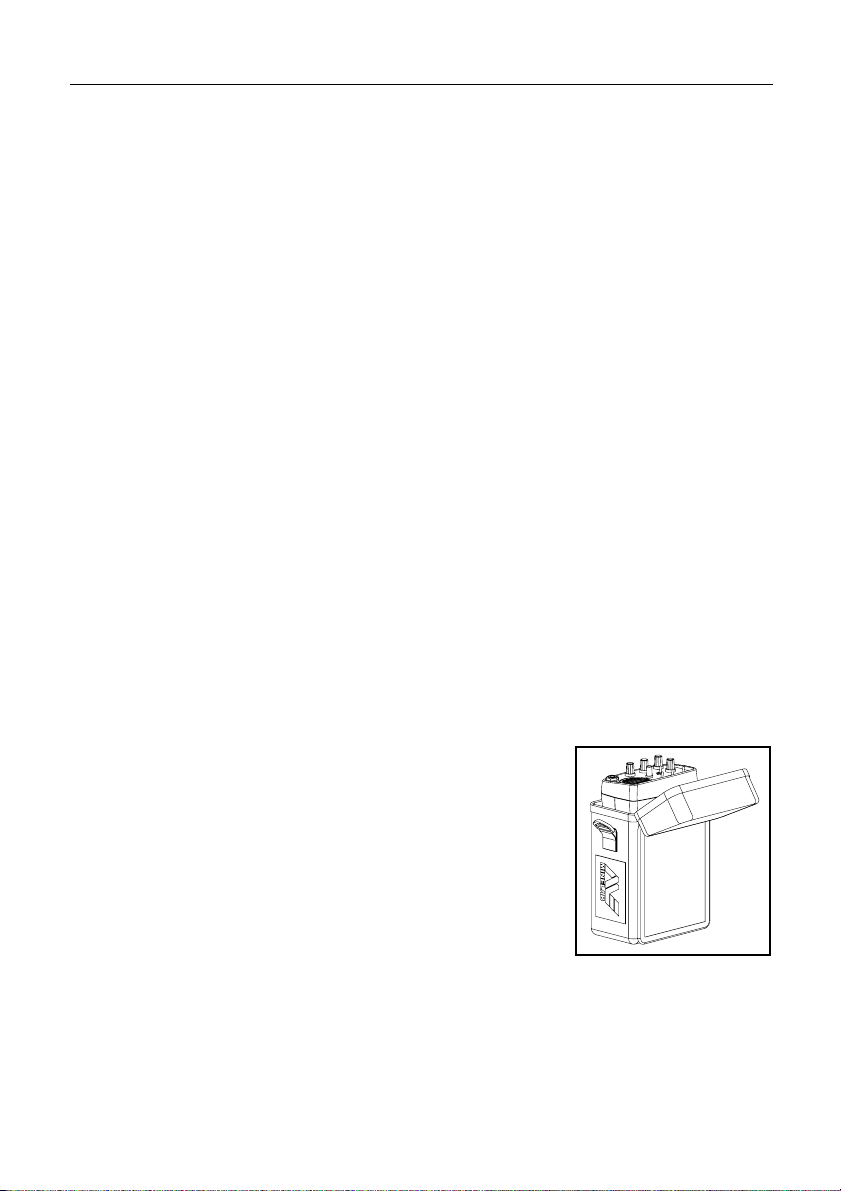
4.1 Installation of NiMH Battery Pack
a) Ensure your NiMH pack is fully charged.
b) Place the base of the battery pack at the rear
of the battery compartment (A). Push the front
edge of the battery pack into position (B). The
two battery clips will “click” into position to hold
the battery pack in place (see figure 9).
Note: The NiMH battery pack is factory sealed
and does not open.
Figure 9 - Installing
the Battery Pack
Page 12

Page 12 The Minelab Eureka Gold
16
15
4.2 Installation of Alkaline Batteries
A 12 Volt battery pack to hold 8 ‘AA’ alkaline batteries is available as an
accessory item. These are useful to have as back-up if ever your NiMH
batteries are flat.
a) Ensure the detector is switched “Off” before opening the battery
compartment.
b) Slide open the lid on the battery pack.
c) Place 8 “AA” alkaline batteries (16) into the
base of the alkaline pack (15). Ensure they
are aligned as shown in figure 10 and as
indicated inside the compartment.
Figure 10 - Replacing
d) Slide the battery lid closed.
the Battery Lid
e)Place the base of the battery pack at the rear of the battery
compartment (A). Push the front edge of the battery pack firmly into
position (B). The two battery clips will “click” into position to securely
hold your battery pack in place (see figure 9).
Caution: Good quality alkaline batteries will power the Eureka for about 10
to 15 hours and should always be used instead of standard carbon
batteries. Alkaline batteries should be removed from the detector if it is to
be stored for extended periods to avoid damage caused by leaking batteries.
Using headphones will extend battery life.
Page 13

Page 13 The Minelab Eureka Gold
4.3 Low Battery Warning and NiMH Recharging
When the batteries are reaching the point at which they will no longer
operate, the Eureka Gold will emit a distinct sharp “pip” from the speaker,
approximately every 30 seconds. Shortly after this, the threshold will
increase to a loud continuous signal that cannot be reduced by the threshold
control. When this tone is heard, it is recommended that the NiMH battery
pack be recharged or alkaline batteries be replaced as soon as possible to
avoid missing any targets. The NiMH battery pack can be recharged using
either the supplied mains powered charger or a 12V charger (available as
an accessory) that can be plugged into the cigarette lighter of your vehicle.
Caution: Check the mains charger voltage. Only use the appropriate mains
charger for the country you are in.
4.4 Using your NiMH Chargers
Plug the charger into the socket on the rechargeable NiMH battery pack,
and plug the charger into the power source and switch on. The car charger
has a red light that indicates that it has power. A green light will appear on
the battery pack during charging. A completely flat battery will take
approximately 12-14 hours to fully charge. The green light on the battery
pack will fade/dim once it is fully charged. A fully charged NiMH pack will
give between 15 and 20 hours detecting time, depending on the number of
targets found.
Figure 1 1 - Car and Mains Battery Chargers
Page 14
Page 1 The Minelab Eureka Gold
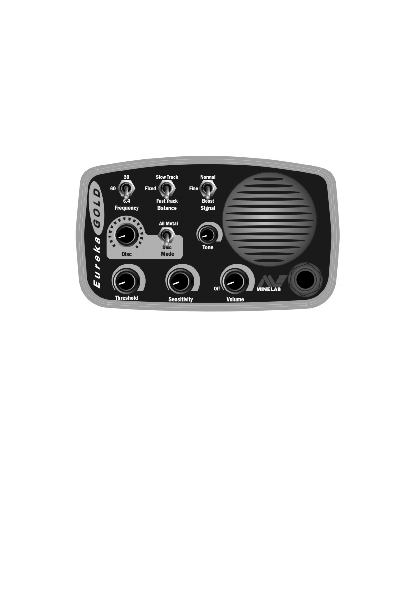
5. The Eureka Gold Controls
This section gives detailed descriptions of the controls of the Eureka Gold
detector and their functionality . Having knowledge of these controls means
that you will be able to achieve the best performance from your detector.
As you gain experience with your detector it may be useful to refer back to
this section.
Figure 12 - The Eureka Gold Control Panel
The Control Panel of the Eureka Gold has been carefully designed,
especially the placement of the controls, so those you will need to use
most frequently are at your finger tips (see figure 12).
5.1 Volume Control
The Volume Control incorporates the On/Off switch. It is off when the
control is fully counter clockwise. Turn the Volume Control clockwise and
the Eureka Gold ‘clicks’ on.
This control sets a maximum limit on the loudness of the audio signal
obtained from various targets. If the Volume Control is close to the
maximum, the audio signal is proportional to the target signal level
(see figure 13). However, if the Volume Control is turned down, the audio
signal is the same for a smaller target, but limited for a bigger target.
Page 15

Page 2 The Minelab Eureka Gold
Figure 13 - Volume Control (The maximum audio output (volume) can be limited)
Therefore this control is a volume limiter. It is a useful feature when using
headphones, as audio signals which would otherwise be uncomfortably
loud can be limited while maintaining full response to small signals.
5.2 Threshold Control
The Threshold Control is used to set the continuous audio ‘hum’ or
‘threshold’ level. The Threshold Control should be set so the threshold
level is just audible, e.g. not too loud. Prolonged use at a loud level could
be irritating to the operator , and could mask a faint signal.
It is important to know that small targets or large but deep targets may not
produce a distinct audio signal, but rather cause only a slight deviation
from the threshold level. If the threshold level is set too high or too low, the
very small variations in audio signal which indicate very small or deep
targets can be missed (see figure 14).
Note: While detecting, the Threshold Control may require occasional
readjustment.
Figure 14 - Threshold Control Settings
Page 16

Page 3 The Minelab Eureka Gold
In the graphs (on page 13) the dotted line represents the level at which the
audio output becomes audible; signals cannot be heard if they are below
that dotted line. When the threshold is set correctly it is just above being
audible and even small variations in the sound level will be heard. If the
threshold level is set too high, then small variations in audio signal might
not be discernible above the threshold level. If the threshold level is set too
low there is no audible background audio signal and small target signals
will not go above the threshold of audibility .
5.3 Sensitivity Control
The Sensitivity Control affects the strength of all signals, small shallow
targets, large deep targets, mineralisation and other interferences. The
Sensitivity Control also affects the level of sound produced by the detector
for a particular target. However, unlike the Volume Control, it affects both
small and large targets alike.
It is recommended that in most ground the Sensitivity Control should be
set to the maximum sensitivity . This is obt ained by turning the control fully
clockwise.
Figure 15 – Sensitivity Control
(The audio output is amplified according to the Sensitivity setting)
The Sensitivity Control should be decreased only in case of electrical
interference or poor ground conditions such as heavy mineralisation or
heavy ironstone. The sensitivity should be decreased just enough to make
the detector usable.
Page 17

Page 4 The Minelab Eureka Gold
5.4 Frequency Switch
The Eureka Gold has three operating frequencies:
6.4kHz, 20kHz and 60kHz. Usually 6.4kHz is better suited
to larger, deeper gold nuggets while 60kHz is better for
smaller nuggets near the surface. The 20kHz setting is
best for general purpose detecting, or a happy medium
P0216-B
between both these extremes.
After changing the frequency setting, there will be a period of 2 seconds
when the detector will not detect any targets. Also, it might be slightly out
of ground balance, but the Automatic Ground Balance will quickly readjust
itself as you start sweeping the ground. If you want to make sure you don’t
miss any targets, you can ‘pump’ the detector as explained in the
Operating Instructions (see pages 23-25).
5.5 Signal Switch
The Signal switch provides three levels of audio response:
Normal, Fine and Boost. In the Normal position, a target
signal is uneffected. A change in the pitch and volume
helps to separate target signals from the background
threshold tone.
P0217-B
In the Boost position, the target signal is amplified, offering
extreme depth penetration in quiet soils or in an area with constant ground
mineralisation. Y ou are likely to encounter some spurious noise if you search
in variable ground using the Boost setting. This mode is also useful to
pinpoint a target which gives a faint signal under normal circumstances.
Noisy (i.e. mineralised) ground will become even noisier if used in this
position. The signal will become even noisier if used in
conjunction with 60kHz.
The Fine position is specially designed to enable the detection of small
and medium size targets close to the surface, especially in mineralised
ground. It does this by amplifying and filtering the audio signal. This allows
the target signals to be amplified without amplifying the background
signals as occurs in boost mode. This mode may miss larger targets at
greater depths but will give greater sensitivity to smaller targets.
Excessive numbers of ‘hot rocks’ could make this mode undesirable in
some grounds.
Page 18

Page 5 The Minelab Eureka Gold
5.6 Balance Switch
The Balance switch selects either Automatic Fast Track
or Automatic Slow Track, or the Fixed ground balance
position. In the two automatic positions the Eureka Gold
is an Automatic Ground Balance detector. This means
that the detector continually adjusts itself to maintain
P0580-A
ground balance, which will ensure that your detector is
searching to its greatest possible depth at all times. Fast Track causes
the ground balance to respond rapidly to changing ground conditions, while
the Slow Track setting responds at about half this rate.
Fast Track being the faster ground balance should be used where the
ground is heavily mineralised or changes rapidly. For ground which is more
mild or reasonably constant in its mineralisation, use the slower
Slow T rack.
It is important to know that a deep target may be ‘balanced’ out by
continual sweeping over it when pinpointing in the automatic modes. By
ground balancing next to the target then switching to the Fixed mode, the
target cannot be balanced out. For the same reason the Fixed mode is
recommended when locating targets once dug from the hole.
5.7 Mode Switch (Disciminate/All Metal)
The Discriminate switch allows the use of
the discriminator built into the Eureka Gold.
It has two positions: All Metal and
Discriminate. In the All Metal position, the
detector responds to all types of targets with
P0221-C
the same target response.
In the Discriminate position, the detector discriminates between ferrous
and non-ferrous targets. The discriminator generally performs best on loud
signals. Its ability to Discriminate between ferrous and non-ferrous targets
may be affected by the depth and size of a target. Ferrous targets will be
signalled by a blanking of the audio threshold. Using the Eureka Gold
discriminating mode will not sacrifice sensitivity or depth, but it will not
necessarily discriminate to the full depth at which the target can be
detected.
Page 19

Page 6 The Minelab Eureka Gold
5.7.1 Discriminate Control
The Discriminate control sets the sensitivity to ferrous objects. At the
minimum setting small ferrous objects at shallow depths are less likely to
be discriminated, while at the maximum setting these objects are more
likely to be discriminated. Large ferrous objects should always be
discriminated unless they are too deep.
5.8 Tone
The Eureka Gold has a tone control which allows the
operator to adjust the “tone” or “pitch” of the audio threshold
signal to suit the individual. Generally , this should be set to
the pitch that you find the easiest to listen to.
P0581-A
We would recommend that you experiment by testing on various targets
buried at different depths to find the tone that best suits your hearing.
5.9 Headphones
The headphone socket is located at the bottom right
corner of the front panel. Headphones used should be
of low impedance, but no less than 8 ohms. The socket
will accept most mono and stereo headphones with a
¼" jack.
When the headphone plug is inserted, the loudspeaker is automatically
disconnected so that sound only comes through the headphones.
When using headphones, you can adjust the Threshold control to a lower
threshold level, and outside noises, such as wind, will be less distracting.
Using headphones also conserves battery life. If the headphones have a
“Stereo/Mono” switch, set it to “Stereo”.
Headphones can significantly increase your chances of hearing a small
signal, therefore we recommend their use.
Page 20

Page 7 The Minelab Eureka Gold
5.10 Coils
The Eureka Gold should only be used with coils that have been indicated
by Minelab Electronics as being suitable for use with this model.
The 10” (25 cm) coil supplied with the Eureka Gold is a Double ‘D’ coil, that
is, it contains two ‘D’ shaped windings which are partially overlapping. This
Double ‘D’ configuration is ideal for locating deep targets in variable
mineralised ground.
The Double ‘D’ detection pattern is “blade like” and is most sensitive from
its tip to its heal. This makes pinpointing targets easy, and allows more
ground to be searched with each sweep, as each sweep has to be
overlapped less.
Double "D"
Lines indicate
areas of maximum
sensitivity
Profile of sensitivity
along Double coil
at various depths
"D"
P0587-A
Figure 16 - Coil Search Pattern
In addition to the 10” (25cm) Elliptical Coil supplied with the Eureka Gold,
there are two other accessory coils available, the 1 1” Round and 15” Spider
Coils. Both coils will increase the depth of the Eureka Gold on larger
nuggets.
Page 21

Page 1 The Minelab Eureka Gold
6. QuickStart Operating Instructions
a)Switch On the power with the Volume control.
b)Set the Volume control to maximum.
c) Set the Sensitivity control to maximum.
d)Set the Threshold control so that the audio level is just audible.
e)Set the Tone control to a pitch you find comfortable.
f) Set the Mode switch to All Met al.
g)Set the Signal switch to Normal.
h)The Disc. control is disabled when in All Metal mode.
i) Set the Frequency switch to 6.4kHz for detecting large, deep targets or
60kHz for small shallow targets or 20kHz for general purpose searching.
j) Select the Fast Track (1) for automatic ground balacing in most heavily
mineralised ground conditions (see section 5.6 for more information).
k) Ground balance the detector by raising and lowering the coil just above
the ground in an area free of targets. Correct ground balance is achieved
when there is no change in threshold hum as the coil is raised and
lowered.
l) Start searching.
Minelab recommends that you read this instruction manual in full, so that
you understand the true function and purpose of the controls. This will
allow you to select the control settings for different conditions.
Page 22

Page 2 The Minelab Eureka Gold
6.1 Best Setup Positions
Gold Field Setting
Signal: Normal
Frequency: 20 or 60kHz
Select: All Metals
Threshold: Just audible
Sensitivity: Maximum
Volume: Maximum
Balance: Fast Track or Slow Track
Other Ground Settings (coins/relics)
Signal: Boost
Frequency: 6.4kHz
Select: Discriminate
Threshold: Just audible
Sensitivity: Maximum
Volume: Maximum
Balance: Slow Track
Tone: Personal Choice
Disc Control: Minimum
Note: The above are only recommended QuickStart positions. It is better
to understand each function and select specific settings for your location.
These settings will often change through the course of the day.
Page 23

Page 3 The Minelab Eureka Gold
7. Detector Sounds
There are seven types of sounds that the detector will produce:
••
• Threshold Signal — A low-level, constant audio hum which is present
••
at all times, even when the coil is held motionless.
••
• Target Signal — Small or large variations in the volume and pitch
••
generally indicate metal targets.
••
• Iron Signal — When the Discriminate switch is set to Discriminate,
••
ferrous targets will be signalled by a blanking of the Threshold
signal.
••
• Overload Signal — A high-pitched squeal indicates the presence of
••
a very large target or very highly mineralised ground. To overcome
this, raise the coil and test the area again. If mineralised ground is the
problem, re-ground balance or try a different signal setting.
••
• Discriminator Overload Signal — A loud ‘bell-ringing’ sound
••
indicates that the Eureka Gold has detected a signal too large for the
discriminator to process accurately. To overcome this, raise the coil
from the ground, so that the signal from the target is weaker .
••
• Low Battery Signal — A sharp ‘pip’ occurs approximately every
••
12 seconds when the useful charge of the batteries is near its end.
••
• Ground Noises — When passing across rapidly changing
••
mineralised ground, ‘ground noises’ may be heard. These are often
more like long growls than the normal short, sharp target signals. They
are often heard when the coil passes across the area from one
direction only . The sound is often not heard from the reverse sweep.
Page 24

Page 4 The Minelab Eureka Gold
8. Operating Instructions – Fundamentals
The Eureka Gold is a motion detector and must be moving over a target to
be able to detect it. If the coil is held still for a few seconds, any signals due
to ground or targets will die away. The Eureka Gold is designed to be
sensitive to a large range of targets while also having the ability to
discriminate between ferrous and non-ferrous targets.
When in use, the detector should have the Threshold control set so that
there is a soft but audible signal at all times. Any variation in this signal as
the coil is moved over ground can indicate the presence of a metallic
target. It could also, however, be due to sudden large variations in soil
conditions for which the automatic ground balance cannot compensate
quickly enough. Such differences can be learned through experience.
8.1 Operating the Eureka Gold
a)Remove the components from the carton and assemble the detector.
b) Ensure the battery is fully charged.
c) Turn the Eureka Gold On using the Volume control. To extend the battery
life, avoid leaving the detector On unnecessarily .
d)Adjust the Threshold control until the audio signal is just audible when
the coil is held motionless. It must be audible, as small targets might not
produce enough signal to make any sound if the background sound is
too quiet. However, if the threshold hum is too loud, small variations
might also be missed because they are too small compared with the
background sound.
e) Once the initial turn-on noises have subsided, turn the Sensitivity
control to maximum then rest the coil on the ground. Once again, after
a few seconds, the noises due to the movement will die down. If there
are any residual noises, they will be due to electrical interference with
the detector. You will need to slighly decrease the Sensitivity control
until the interference noises are stable. Reduction of sensitivity
reduces the ability to detect targets, so the sensitivity should be
reduced as little as possible.
Page 25

Page 5 The Minelab Eureka Gold
f) The Volume control is generally turned to maximum. The setting does
not affect the threshold level, but sets a limit on the loudest audio
signal produced. Test the volume comfort level by passing a piece of
metal over the coil. Adjust the Volume control to a comfortable level.
g) Adjust the Tone control to a pitch to which your ears are most
sensitive. This again allows you to have the threshold set to as low a
level as possible.
h)It is recommended that the Balance switch is set to either Fast Track or
Slow T rack for general detecting. The Fixed setting can be used to hold
the ground balance in localised areas when it is suspected that small
targets are being balanced out (see Balance Switch on page 17).
Leaving the setting at Fast T rack or Slow Track while detecting will ensure
that the Eureka Gold continuously adjusts itself to the
changing ground conditions. Note that sudden changes in the ground
conditions may still produce changes in the audio signal and
balancing may need to be repeated.
i) Move the coil up and down near the ground surface. This allows the
Automatic Ground Balance feature to set the
balance. Keep ‘pumping’ the coil until there is
no change in the audio signal accompanying
the movement (see Figure 17).
j) Start searching by slowly moving the coil
across the ground. Periodically check the
control settings to correct for any change in
the detector or soil conditions. Refer to
‘Detecting Techniques’ (see pages 26-30)
for details on finding targets.
Figure 17 - Ground
Balancing
Page 26

Page 6 The Minelab Eureka Gold
8.2 Ground Balance
Generally speaking, without the ground balance of the detector being set,
passing the coil over an area of ground may produce signals whether or
not there are targets in the ground. Signals produced without the presence
of targets are due to the magnetic and/or mineralised nature of the soil.
To eliminate these unwanted signals the automatic ground balance of the
Eureka Gold must be enabled by switching to either Fast Track or
Slow Track. In these modes the Eureka Gold automatically adjusts its
ground balance.
When first turning the detector On, switch it to either Fast Track or
Slow Track and raise and lower the coil repeatedly over the ground until
the audio signal is constant.
In heavily mineralised ground, Fast T rack will re-balance more rapidly and
therefore maintain a better ground balance, however, very weak target
signals could be eliminated if repeated sweeps are made across the
target. In less mineralised areas, Slow Track will maintain a good ground
balance without tracking out targets. Once a target has been located, the
detector should be put into Fixed for pinpointing and digging the target.
Note: It is possible for small targets to be balanced out if the detector coil is
swept repeatedly across the target. Once a signal is located, the Balance
switch should be changed into Fixed mode.
Page 27

Page 7 The Minelab Eureka Gold
9. Detecting Techniques
For best results with the Eureka Gold, it is recommended that you learn
some basic detecting techniques such as sweeping, pinpointing and
digging targets.
9.1 Sweeping
One of the most important detecting techniques, and perhaps one of the
hardest to perfect, is the sweeping of the coil across the surface of the
ground.
The Eureka Gold is a motion detector which means that in order to detect
a target the coil must be moving. It is recommended that you use a
sweeping motion for the coil while detecting (see figure 18). It is
essential that the coil sweeps are overlapped in order to ensure that all
ground is searched.
Figure 18 - Sweeping the Coil
Note: Each sweep of the coil should overlap the last one. This will ensure
good ground coverage.
Page 28

Page 8 The Minelab Eureka Gold
Sweeping is carried out in a uniform motion along the ground to cover the
search area. Keep the coil parallel to the ground at all times and be aware
that there is a tendency for the coil to be raised at the end of each sweep
(see figure 18). Each sweep from one side of the body to the other should
take between 2 and 4 seconds to complete. This speed will depend on the
soil conditions and on the area in which you are operating. V ariation in coil
height at the end of each swing can cause confusing sounds and will
reduce detection depth. Increased noise can also result from hitting rocks,
etc. Where possible, keeping the coil in contact with the ground will
increase detection depth and sensitivity to very small targets.
9.2 Pinpointing the Target
When a target has been detected, it is necessary to accurately determine
its position to enable the operator to recover it quickly and minimise any
damage to the environment.
You should switch back to the Fixed Ground Balance position to pinpoint
the actual location of the detected target. Sweep the coil over the general
area taking note of where the strongest signal is received as the coil is
moved over the target. By decreasing the length of the sweep it should be
possible to draw an imaginary line in the ground where the strongest
signal is located (see figure 19). The side of your boot can be used to mark
the ground along this line.
Figure 19 - Pinpointing the T arget
Page 29

Page 9 The Minelab Eureka Gold
The target could be anywhere along the length of the coil from head to toe.
In order to pinpoint its exact location, it will be necessary for you to turn at
a 90 degree angle and repeat the sweep across the target.
Again take note of the point where the strongest signal is and draw another
imaginary line in the ground. Where the two imaginary lines cross is where
the target is located. Use the side of your boot to mark this location if
necessary.
9.3 Digging the Target
Always remember that when digging, the hole should be kept as small as
possible to keep the size of the hole to a minimum.
Dig carefully as a heavy blow can split a nugget, causing a drop in its
value. All holes dug must be filled in once the t arget has been recovered.
It is advisable to have some sort of digging tool when searching. Useful
tools are:
• A small hand pick with pointed end and wide blade the other end.
• A small strong digging spade.
• A small knife for grassy areas.
Before digging, clear the surface material and check that the signal is still
there. If there is no longer a signal, then the target must be amongst the
surface material and is possibly trash. If the signal is still there, dig down a
few centimetres. Dig a dish-shaped hole; any sharp edges of soil might
cause a false signal.
If the target is not visible, sweep the coil over the hole. The signal should
become louder so continue to dig. If the signal has gone then the target
should be in the pile you have just dug. If the target is not clearly visible,
you might need to scan the soil which has been dug up, so be sure to pile
the soil carefully while digging.
The target can be located in this soil by the following methods:
a)When digging and locating the target, ensure the Balance control is set
to Fixed.
b)Sweep the coil over the pile of soil to locate the target. Be sure that there
are no targets buried under the soil directly below the pile.
Page 30

Page 10 The Minelab Eureka Gold
c) Lay the detector down with the coil flat on the ground, near the hole.
d)Pick up a handful of soil from the pile where you located the target and
pass it across the coil. If there is no signal then place the soil in a
second pile away from the first and grab another handful from the same
area of the pile. Continue this process until the target is in your hand.
Look through the soil in your hand until you find the target.
e)If the target is not obvious, dribble the soil slowly from your hand onto
the top of the coil and listen for the target signal.
f) Then use your fingertip to nudge any suspect items on the coil. The
detector will signal when the target is moved.
Once the target has been recovered it is a good idea to run the detector
over the hole again to make sure that there are no other targets to be
found. When you have recovered all targets from the hole, it is advisable
to search the surrounding area carefully as there is a high chance that
more targets will be nearby.
9.4 Automatic Ground Balancing
These simplified diagrams (see Figure 20 overleaf) show how Automatic
Ground Balancing with the Eureka Gold allows you to detect to its
maximum depth at all times.
The top diagram shows normal searching without Automatic Ground
Balancing. Ground mineralisation reduces the effective searching depth
when you move from where you last ground balanced. The shaded area
shows ground which is not properly searched.
The centre diagram shows how a hardworking, experienced professional
with a manual ground balance machine will reduce this effect to a
minimum. The detector is rebalanced more often, and this is very
time-consuming.
The bottom diagram shows how genuine Automatic Ground Balancing
covers all the ground quickly and effectively. This ensures that the
detector with automatic ground balancing will give optimum depth at all
times. For this to occur, the detector must balance quickly enough and still
retain sensitivity .
Page 31

Page 11 The Minelab Eureka Gold
Figure 20 – Automatic Ground Balancing
Page 32

Page 12 The Minelab Eureka Gold
10. Discrimination
10.1 Discrimination of Iron Targets
When the Discriminate switch is set in the Discriminate position, the Eureka
Gold is able to discriminate between ferrous (iron) and
non-ferrous targets (valuables).
A unique feature of the discriminator is its ability to read the degree of
ground interference during discrimination. The detector automatically
adjusts its discriminating power depending on the type of ground present,
thereby achieving the maximum reliable discrimination depth.
Therefore in ‘mild’ ground the detector will discriminate accurately at greater
depth, while in ‘hot’ ground, the discrimination depth is reduced to
maintain reliable discrimination. At all times, however, the depth and
sensitivity that the Eureka Gold picks up targets is not reduced.
Be aware that if the detector coil is held in the air or stationary over ground
for an extended period, the discrimination sensitivity increases to maximum.
If it is then used on ‘hot’ ground, false discrimination signals will appear .
It is important to keep the coil swinging in a smooth motion at all times.
After a short time, however , the detector will adjust to its new condition and
the sensitivity of discrimination will automatically be set correctly .
To obtain the best performance out of your discriminator we suggest you
take advantage of the multiple frequency features of the Eureka Gold. The
best frequency for discrimination is 6.4kHz, followed by 20kHz and then
60kHz. It is best to:
• Search for gold at 20kHz or 60kHz in Fast Track or Slow T rack mode.
• Check the ferrous nature of a located target in Fixed mode at 6.4kHz.
10.2 Discriminating in ‘Hot’ Ground
If detecting in Fast Track or Slow Track and the detector is in
Discriminate mode, there are several techniques that must be followed for
accurate discrimination. As mentioned earlier, the Eureka Gold
incorporates a unique feature that adjusts the sensitivity of the
discrimination, depending on the ground conditions.
Page 33

Page 13 The Minelab Eureka Gold
If the detector is swept across the target more than once in ‘hot’ ground it
is possible that the detector’s automatic features will adjust the balance to
the target and not discriminate out a ferrous target on subsequent passes.
This is normal behaviour for an automatic ground balance detector.
Because of the different speeds of adjustment in the two ground tracking
modes there will be a difference in the speed of this automatic adjustment.
In Fast Track only the first pass over the target will achieve accurate
discrimination. In Slow Track the first two passes are accurate.
To ensure that you are not digging ferrous targets it is best to carry out the
following procedure once you suspect a target has been discriminated:
• Move the detector off the target and ground balance the detector over
metal-free soil.
• Set the detector in Fixed balance mode.
• You can now pass the coil over the target as many times as you like
and the discrimination will be accurate.
10.3 Discriminating within Holes
The discriminator must not be used to test a target by pumping the coil
into the hole. Always pass the coil smoothly across the top of the hole.
Moving the detector coil within the hole will often produce a ‘non-ferrous
type’ target signal when the target is really ferrous.
Similarly, the discriminator should not be used to test a target within the
pile of soil which has been taken from this hole as again ‘non-ferrous type’
signals are likely to occur, particularly in highly mineralised ground. The
discriminator will give the most reliable result when the target is tested
while it is on or within undisturbed ground.
When the search coil is passed over large targets near the surface, the
discriminator electronics may sometimes overload. This is indicated by a
high pitch ‘chirp’ or ‘bell-ringing’ sound. Sweep the search coil further above
the target or so that the target signal is less strong.
Page 34

Page 14 The Minelab Eureka Gold
11. Prospecting Tips
It will take time and practice to learn how to recognise which signal to
pay attention to or to ignore.
The Eureka Gold is particularly good at minimising ‘ground noises’, and
this is the reason for the exceptional depth capability . However, even with
this detector some ground noises may occur, particularly in heavily
mineralised ground.
11.1 Mineralisation and Hot Rocks
Typically , heavily mineralised ground can make a detector respond with an
indication that there may be a target reasonably deep beneath the surface.
The sound is normally rather broad and not very loud, but occasionally it
may be crisp and reasonably sharp. Other noises which most affect
detectors are caused by ‘hot rocks’. These are rocks rich in minerals
which can produce very strong audio signals. With the strong ones, some
detectors have problems in tuning them out, but with the Eureka Gold signals
from ‘hot rocks’ are not as great a problem.
If you find a signal which may be due to mineralisation, but is ‘positive’
enough to make you suspect a deep target, pass the coil in a circular path
around the area, without passing directly over the target. After two or three
rotations, pass the coil directly over the centre and listen to the
‘positiveness’ of the signal. Repeat this procedure but this time sweep at
right angles to the previous pass. If both passes result in a significant
positive response, then dig!
It is possible for gold nuggets to be entirely encased in rocks, so thorough
checking is necessary to ensure no gold is missed. Breaking rocks in two,
then passing each section of the rock across coil, one after the other, will
determine which piece contains the gold.
Sometimes negative ‘hot rocks’ or ground ‘holes’ are encountered. In this
case the sound from the detector is reduced as it passes over the rock or
‘hole’. Nevertheless, the detector, on recovering from this loss of sound,
can give an audible signal which, to the beginner, may be confused with
the sound of a target. Experience will soon enable the operator to
recognise this characteristic sound which is in fact quite different from a
target. Setting the Signal switch to Fine may reduce this problem.
Page 35

Page 15 The Minelab Eureka Gold
11.2 Clay Domes
A common occurrence in nugget-bearing country is soil mineralisation
commonly known as ‘clay domes’. These are regions of rather broad sound
which could be confused with the sound which would come from a large
deep nugget.
The following procedure will quickly establish whether or not the sound
comes from clay or a metal target:
a) Pinpoint the target as best you can.
b) Remove about 4 cm (1.5”) depth of soil from over the target response.
Dish the hole so that there are no sharp edges around the hole.
c) Sweep the coil across the target from a few directions, keeping the
coil as low as possible. Listen to the signal and note if it is:
— Any louder or more defined than before. By bringing the coil closer
to a metal target the signal should become louder .
— Note if the signal seems to come from one direction only
(a mineral signal will often come from one direction only, or at
least be less defined from the return sweep).
d) If you are still not sure, continue to dig deeper and again, note the
points above.
e) Be sure to dish the hole when digging to ensure there are no sharp
edges. Sweeping the coil across the sharp edge of a hole can cause
false spurious signals due to the change in distance between the
ground and the coil.
11.3 Charcoal
Charcoal can sound loud and rather like a metallic target when close to
the surface. Charcoal is usually created by farmers burning off tree stumps
or by bushfires. The growth is burnt below the ground level, so it is not
always obvious what the sounds are until you have actually dug up the
causes of these noises a few times. Again, experience will teach the
operator how to read the ground efficiently and gain understanding of the
detector’s response to the ground.
An indication of charcoal is that the sound seems very spread out and
becomes patchier as the ground is dug. Inexperienced operators should
continue to dig until the reason for the signal becomes clear.
Page 36

Page 16 The Minelab Eureka Gold
11.4 Gold Lore
To have a good chance of detecting gold, it is necessary to search out
areas where ‘coarse gold’ is known to have been found, or other areas
where it is likely to occur. The term ‘coarse gold’ refers to gold ranging in
size from a grain of wheat to many grams, and in some cases many
ounces.
Many nugget-bearing areas are the result of broken-down gold reefs
containing quartz and ironstone. Experienced prospectors learn to
‘read the ground’ and look for tell-tale signs indicating potential
gold-bearing fields. It is a fascinating and exciting hobby to learn some of
these skills and apply them in your search for gold.
The modern metal detector has given today’s prospector enormous
advantages over the prospectors of old. The ground can be rapidly scanned
until a small piece of gold is found and then a study of the area made to
decide where other gold nuggets are likely to be located. It is then best to
make a systematic search of the area.
The main problem encountered while using metal detectors is the
presence of heavy concentrations of ironstone. This is particularly the case
in some of the richest known fields in Australia or the ‘black sands’ areas
of North America. It appears that gold nuggets and ironstone often go
together , and in fact many gold nuggets have ironstone embedded in them
or are encased in ironstone and others show strong ironstone
staining. Some of these fields have only been superficially worked by
detectors because of the interference caused by the ironstone. Usually
only the most persistent professional is prepared to spend the time and
energy necessary to cope with these conditions and then only partially.
Page 37

Page 17 The Minelab Eureka Gold
12. The Coil and Skidplate
Over a long period of time the Coil Skidplate will wear if the ground is
scrubbed continuously while searching. Minelab agents can supply a
replaceable skidplate for the Coil. This can be fitted by removing the
existing plate and pushing on the replacement skidplate (see Figure 21).
Skidplates are inexpensive and it is recommended that you protect your
coil by regularly replacing the skidplate.
P0584-A
Figure 21 - Skidplate to Protect Coil
Hint: The use of non-metallic tape around the edge of the coil/skidplate will
help to prevent the ingress of dirt or moisture.
Page 38

Page 18 The Minelab Eureka Gold
13. Environmental Concerns
Firstly , it should be pointed out that gold prospecting and treasure hunting
with a metal detector is the most environmentally friendly way to recover
nuggets, coins, rings, and other treasure items. However , it is important to
leave an area that you have searched in the same condition as you found
it.
All holes that have been dug must be properly refilled. Not only is it
environmentally unacceptable to not fill in your holes, it is also very
dangerous. There are special tools to enable you to recover targets easily
from grassed areas without digging large holes.
T ake away and properly dispose of any junk that you find or produce, such
as nails and tin cans. Use a rubbish pouch on a belt to collect the rubbish
while searching and dispose of it environmentally when you return home.
Leaving an area ‘scarred’ can result in action being taken to prevent the
use of metal detectors, which spoils this fascinating hobby for others as
well as yourself.
Page 39

Page 19 The Minelab Eureka Gold
14. Care of the Eureka Gold Detector
The Eureka Gold is a high-quality electronic instrument, finely engineered
and packaged in a durable housing. Proper care and maintenance will
ensure long-term reliability of the detector.
Please observe the following precautions:
••
• Do not leave the alkaline batteries in the control box when the
••
detector is not in use. Damage caused by leaking batteries can be
severe and will void the warranty .
• If temperatures are very high, do not leave the detector in the sun for
longer than necessary . Covering it when not in use will help protect it.
Try to avoid leaving it in a closed trunk or behind glass sitting in
sunlight.
• While the control box has been designed to be water-resistant, it is not
waterproof. A void wetting it unnecessarily. Never allow the box to come
into contact with gasoline or other oil-based liquids.
••
• Keep the unit (especially connectors) clean and dry , and avoid getting
••
sand and grit into the shafts. Do not use solvents to clean the
detector. Use a damp cloth with mild soap detergent.
••
• Flat or faulty batteries cause many detector problems. Ensure that
••
you use only Minelab NiMH rechargeable batteries and that they are
recharged as soon as the ‘Low Battery’ warning signal is heard.
Ensure that only quality alkaline ‘AA ’ batteries are used and that they
are replaced when the warning signal indicates.
• Ensure that you only use Minelab’s NiMH battery charger as per
previous instructions.
••
• Ensure the coil cable is in good condition and not subject to undue
••
stress.
Page 40

Page 20 The Minelab Eureka Gold
• If any part of the detector comes into contact with corrosive substances
(including salt or salt water), wash it with fresh water.
• Use of a padded transport bag or case can protect your detector from
scratches and bumps while transporting in the vehicle.
• The hipmount bag is designed to protect the control box, especially
from dust, mist and rain. It will also cushion potentially damaging knocks.
Use the hipmount bag where possible.
••
• The Eureka Gold is a very sensitive VLF radio receiver. There are many
••
external sources of noise that may affect the performance of the
detector, including another detector in close proximity, high power
transmitters, power lines and electric fences.
••
• Do not open the control box or attempt to alter the detector in any way .
••
Doing so will void your warranty .
Page 41

Page 21 The Minelab Eureka Gold
14.1 Trouble-shooting Guide
Fault Solution
No Sound Check battery and battery connections
Check Headphones and their connection
Erratic Noises Check battery charge and battery connections
Ensure coil plug is tightened firmly
Reduce the sensitivity by turning
counter-clockwise
Switch out of ‘Fixed’ ground balance position
Check and adjust the ground balance
Check headphones and their connection
Check for sand or grit between skid plate and Coil
No Target Response Ensure unit is turned ‘On’
Check battery charge and battery connections
Check coil connection
Check headphones and their connection
In the unfortunate circumstance that you need to return your detector to
Minelab for service, please fill out a copy of the Minelab Service Repair
Form on page 44 and enclose it with the detector . Please supply as much
detail as possible about the fault and warranty details, as this will assist
our service engineers to rectify the problem quickly and efficiently .
Page 42

Page 22 The Minelab Eureka Gold
15. Warranty and Service
There is a two-year parts and labour warranty for the Eureka Gold
electronic Control Box. The Coil, Shafts, etc., are warranted for one year.
Refer to your Warranty Card for further details. Always refer to your
supplier or Minelab for service, either in or out of warranty .
Note: This warranty is not transferable, nor is it valid unless the enclosed
warranty registration card is returned to Minelab Electronics Pty Ltd or an
authorised Minelab Electronics Pty Ltd regional distributor within 14 days
of the original purchase.
The Minelab warranty does not cover damage caused by accident,
misuse, neglect, alteration, modifications, or unauthorised service. For
specific details of the Minelab warranty, please refer to the
‘Product Warranty Card’.
Page 43

Page 23 The Minelab Eureka Gold
16. Specifications
These specifications are subject to change without notice.
Length: Packed 710 mm
Operating (min) 1190 mm
(max) 1350 mm
Weight: Control Box 740 g
Complete Unit (excl batt) 2.2 kg
Batteries: Recharge NiMH Batt Pack 12V , 1.2Ah ~ 20hr
Coil: 10” Double ‘D’ Elliptical with Skidplate
Frequency: Transmission (sine wave) 6.4, 20 and 60 kHz
Ground Balance: Automatic 2 Speed & Fixed
Search Modes: Motion Detector Always
Balance Fast , Slow & Fixed
Discrimination All Metal and Disc
Controls: On/Off Volume Control 1 turn
Threshold Control 1 turn
Sensitivity Control 1 turn
Tone Control 1 turn
Discriminate/All Metal Switch 2 Pos
Discriminate Level Control 1 turn
Balance Switch 3 Pos
Frequency Switch 3 Pos
Signal Switch 3 Pos
Charger: 110/240V Mains Charger for rechargeable battery
Warranty: Control Box 2 Y ears
Coil 1 Y ear
Patents: Patents apply
Page 44

Page 24 The Minelab Eureka Gold
17. FCC Compliance
NOTE:
This equipment has been tested and found to comply with the limits for
a Class B digital device, pursuant to part 15 of the FCC rules. These
limits are designed to provide reasonable protection against harmful
interference in a residential installation. This equipment generates,
uses and can radiate radio frequency energy and, if not installed and
used in accordance with the instructions, may cause harmful
interference to radio communications. However, there is no guarantee
that interference will not occur in a particular installation. If this
equipment does cause harmful interference to radio or television
reception, which can be determined by turning the equipment off and
on, the user is encouraged to try to correct the interference by one or
more of the following measures:
• Re-orient or relocate the receiving antenna.
• Increase the sep aration between the equipment and receiver .
• Consult the dealer or an experienced radio/TV technician for help.
EC Conformity
NOTE:
This product complies with the essential requirements
of EMC Directive 89/336/EEC
Page 45

Page 25 The Minelab Eureka Gold
18. Minelab Service Repair Form
Today’s Date:..........................................
Detector Model: ...................................... Serial No.:.............................
Purchased From: ..................................................................................
Purchase Date: ......................................
Faulty Part(s):........................................................................................
..............................................................................................................
Description of Fault: ..............................................................................
..............................................................................................................
..............................................................................................................
..............................................................................................................
..............................................................................................................
Owner’s Name:.....................................................................................
Address: ................................................................................................
..............................................................................................................
Phone: Day ( ) ................................. Home ( ) ........................
Fax: ( ) .............................................. Email: ...................................
 Loading...