

Page 1

Instruction Manual
Page 2

Welcome
Congratulations on purchasing your EQUINOX metal detector.
Metal detecting is a fascinating and rewarding activity enjoyed by people all over the
world. By getting to know your EQUINOX detector you can become one of the many who
find coins, treasure, artefacts, gold nuggets and more on a regular basis.
The EQUINOX is a high-performance detector incorporating Minelab’s new Multi-IQ
technology. With the assistance of this Instruction Manual, and the accompanying Getting
Started Guide, you will quickly learn how to set up your detector for the best results.
Minelab wishes you every success on your detecting
adventures!
The latest product instruction manuals and detector software updates are available at:
www.minelab.com
We also encourage you to visit our other online resources regularly. They are frequently
updated and are a continually evolving source for product information.
@MinelabMetalDetectors
Treasure Talk Blog
Metal Detecting
Code of Ethics
• Respect the rights and
property of others.
• Observe all laws, whether
national, state or local.
• Always obtain permission
before searching sites.
• Never destroy historical or
archaeological treasures.
• Leave the land and
vegetation as it was.
• Always fill in your holes after
digging.
/MinelabDetecting
Success Stories
"At heavily hunted beaches when you need to cover
ground quickly after a busy beach day, the EQUINOX’s
amazing recovery speed helps you to stay one step
ahead of the beach hunting competition."
– Gary Drayton, USA
"EQUINOX is the most exciting detector I have used in
a long time! It just keeps surprising me with what I'm
finding in heavily detected parks."
– Mark Williams, Australia
An asterisk appears throughout the manual, indicating features only included with the EQUINOX 800 model.
Page 3

Contents
Assembly & Getting Started
Detect Screen Functions
Target Tone 46
Selecting the Number of Target Tones 46
Carton Contents 5
Assembly 6
Assembled Detector 7
Detector Battery 8
Charging the Battery 8
Battery Status Indicator 8
Battery Maintenance 8
Operating With a Power Bank 8
Control Panel 9
LCD Icons 10
Quick Start 11
Global and Local Settings 12
Reset a Search Profile 12
Factory Reset the Detector 12
Detecting Basics
How Detectors Work 14
Key Detecting Concepts 15
Detecting Technique 16
Holding the Detector 16
Adjusting the Length of the Shafts 16
Adjusting the Angle of the Coil 16
Sweeping the Coil 16
Targets 16
Detector Sounds 17
Simple Detecting Exercise 18
Pinpointing Technique 19
Coil Configuration and Pinpointing 19
Pinpointing a Target Manually 19
Target Recovery 20
Digging Tools 20
Recovering a Target 20
Detect Modes
Detect Modes 22
Detect Mode Navigation 22
Adjusting Search Profiles 22
Choosing the Right Detect Mode 22
Park 23
Field 24
Beach 25
Gold* 26
Frequency 28
Changing the Frequency 28
Single Frequency Operation 28
Frequencies and Detect Modes 28
Multi-IQ Technology 29
Target ID & Discrimination 30
Target ID 30
Discrimination Scale 30
Typical Target Examples 31
Target ID Accuracy 31
Backlight 32
Turning the Backlight On 32
Adjusting the Backlight Brightness* 32
User Prole* 33
Save a User Profile 33
Activating the User Profile 33
Sensitivity 34
Sensitivity Indicator 34
Adjusting Sensitivity 34
Recommended Sensitivity Settings 34
Depth Gauge 35
Pinpoint 36
Pinpoint Visualisation 36
Pinpointing a Target 36
Settings Menu
Settings Menu 38
Settings 38
Advanced Settings 38
Settings Menu Navigation 38
Noise Cancel 39
Auto Noise Cancel 39
Manual Noise Cancel* 39
Ground Balance 40
Manual Ground Balance 40
Auto Ground Balance 40
Tracking Ground Balance 41
Volume Adjust 42
Adjusting the Volume 42
Tone Volume (Advanced Setting) 43
Adjusting Tone Volume 43
Threshold Level 44
Adjusting the Threshold Level 44
Gold Threshold 44
Park, Field, and Beach Threshold 44
Threshold Pitch* (Advanced Setting) 45
Adjusting the Threshold Pitch 45
Tone Pitch (Advanced Setting) 47
Adjusting Tone Pitch: 1, 2, or 5 Tones 47
Adjusting Tone Pitch: 50 Tones 48
Accept/Reject 49
Creating a Discrimination Pattern 49
All-Metal 49
Accepting/Rejecting Detected Targets 49
Tone Break (Advanced Setting) 50
Adjusting Tone Break 50
Recovery Speed 51
Swing Rate 51
Adjusting Recovery Speed 51
Iron Bias (Advanced Setting) 52
Adjusting Iron Bias 52
Detector Audio
Audio Options 54
Wireless Audio Latency 54
WM08 Wireless Audio Module 55
Pairing the WM 08 55
Pairing Additional WM 08 Modules 55
Charging the WM 08 55
ML80 Wireless Headphones 56
Pairing Wireless Headphones 56
Adjusting ML 80 Volume 56
ML 80 Factory Reset 57
Charging ML 80 Headphones 57
ML 80 Auxiliary Cable 57
Wired Headphones 58
Connecting Wired Headphones 58
Adaptor Cable 58
Connecting Waterproof Headphones 58
Headphone Socket Submersion 58
Care & Safety
EQUINOX Accessories 60
Maintenance & Safety 61
Battery Charging
Recommendations 62
Factory Presets 63
Troubleshooting 64
Error Codes 65
Technical Specications 66
Software Updates 67
Page 4

Contents
Assembly & Getting Started
This section will show you how to assemble your EQUINOX Series detector, charge the
battery, and will introduce you to the control panel.
Page 5

Carton Contents | 5Contents
Carton Contents
EQUINOX Series detectors come with everything you need to get started detecting.
The EQUINOX 800 comes with additional accessories for even greater versatility.
For a list of the main accessories that are compatible with your detector, read 'EQUINOX Accessories' on page 60.
Go online to see the full range at www.minelab.com/equinox-accessories.
Stand
Armrest
Upper shaft with handle
Middle shaft
Lower shaft
Armrest bolt
Armrest strap
EQX 11 Double-D smart coil
Skidplate (attached)
Velcro tabs (×2)
Coil yoke washers (× 2, attached)
Yoke nut and bolt (attached)
USB charging cable with
magnetic connector
Multi-language screen
protector pack
Getting Started Guide (×2)
(English and Russian)
Included with EQUINOX800Included with
EQUINOX600
3.5 mm (1/8-inch) wired
headphones
WM 08 wireless
audio module
USB charging cable with
magnetic connector
instruction sheet
Hard shell case
ML 80
Items and specifications may vary slightly from those shown and may be subject to change.
Carton contents reference
(English and Russian)
3.5 mm (1/8-inch)
Battery Charging
Recommendations
ML 80 wireless
headphones
USB charging cableAuxiliary cable
Page 6

Assembly
Follow these easy steps to assemble your EQUINOX Series detector.
Attach coil to lower shaft
1. Insert the two yoke washers into the holes on either side of the
yoke.
2. Slide the yoke into the yoke bracket on top of the coil.
Ensure that the spring loaded pin in the lower shaft is
underneath.
3. Insert the yoke bolt through the yoke and the yoke bracket.
4. Fasten with the yoke nut - Do not over-tighten.
1
2
Assembly | 6Contents
3
4
Assemble shafts
1. Loosen the twistlocks by rotating them counter-clockwise.
2. Press the spring loaded pin in the lower shaft and slide it into
the middle shaft until the pin reaches the adjustment holes.
The pin will click into place.
3. Attach the middle shaft to the upper shaft in the same way.
4. Lock the position of the shafts by rotating twistlocks clockwise.
Attach armrest
1. Place the armrest onto the top of the upper shaft. Position the
armrest just below your elbow, then align the central hole in
the armrest with the nearest hole in the shaft.
2. Insert the screw through the stand, upper shaft and armrest.
Tighten the screw carefully.
3. With the velcro side facing upwards, thread the armrest strap
through both slots in the armrest. Ensure the end of the strap
will be fastened outwards from your arm.
1
2
1
3
4
3
2
Connect coil
1. Wrap the coil cable around the lower and middle shaft enough
times to take up the slack, but so the coil can still tilt without
restriction.
2. Use the velcro tabs provided to secure the coil cable against
the shaft.
3. Align the coil connector and plug into the socket in the back of
the control unit, tightening the retaining ring.
1
2
3
×2
Page 7
Assembled Detector | 7Contents
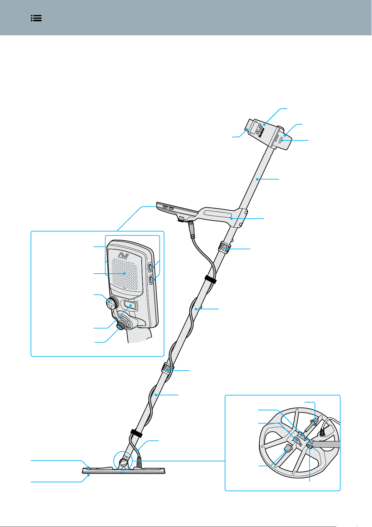
Assembled Detector
Once you have assembled your EQUINOX it should look like the below.
The major parts listed are referred to throughout this Instruction Manual.
Armrest
Stand
Control unit (rear view)
Side buttons
Speaker
Headphone socket
3.5 mm (1/8-inch) with
waterproof dust-cap
Armrest strap
Middle shaft
Attachment
points
Upper shaft
Handle
(With internal Lithium-ion
rechargeable battery)
Upper shaft twistlock
Charging interface
Coil cable connector socket
EQX 11 smart coil
Skidplate
Middle shaft twistlock
Coil yoke assembly
Lower shaft
Yoke bolt
Yoke
Yoke bracket
Coil cable
Yoke nut
Yoke Washers (×2)
Page 8

Detector Battery | 8Contents
Detector Battery
The EQUINOX detector is powered by an internal Lithium-ion battery.
Read 'Battery Charging Recommendations' on page 62 for important safety information.
For instructions on how to charge the WM 08 Wireless Audio Module read page 55. For instructions on how to charge the ML 80
Wireless Headphones read page 57.
Charging the Battery
Going detecting with a fully charged battery is
recommended. Typical battery runtime is
approximately 12 hours.
EQUINOX Series detectors are supplied with a USB charging cable
that features a snap-on magnetic connector.
1. Plug the supplied charging cable into any standard powered
USB-A port.
2. Connect the magnetic connector to the charging interface on
the rear of the EQUINOX control unit.
The green charge status LED on the top left of the control
panel will flash slowly.
3. When the battery is fully charged, the charge status LED will
remain on.
Charge Status LED
Charging (flashing)
Battery Status Indicator
The battery status indicator shows the current battery level.
70% –100%
30% – 70%
<30%
<5% (Charging required)
When the battery level is critically low, ‘bF’ will appear on
the Target ID Display. The detector will then turn off
automatically.
The detector regulates the battery voltage so that its
performance remains constant regardless of the charge
remaining in the battery.
Battery Maintenance
Lithium-ion battery performance may degrade if unused for long
periods of time. Fully charge the battery at least once every 3–4
months to prevent this from occurring.
Even with correct care and maintenance, Lithium-ion battery
performance reduces over time with normal use. Therefore the
battery may need to be replaced every few years. Replacement
batteries can be supplied and installed by an Authorised Service
Centre.
Fully charged (on)
The charge time from completely flat to 100% is approximately 4
hours when a high capacity (>1.7A @ 5V) charger is used. Car and
wall charging accessories are available for separate purchase.
Any standard USB port compatible with USB battery charging 1.2
(BC1.2) can be used to charge your battery, however charge times
may be longer if using lower-power options.
If the detector is turned on during charging, the charge time will
be longer.
Disconnecting the Charger
The charging cable can be removed
from the charging interface by
pulling it sideways, or by pulling it
directly backwards.
Operating With a Power Bank
The detector must not be used underwater whilst
charging or when connected to a power bank.
You can use your EQUINOX detector whilst plugged into a portable
power bank. This means you can continue detecting even if the
detector battery is flat.
Connect the power bank to your detector using the supplied
EQUINOX USB charging cable, and continue detecting. You can
fasten it to the armrest stand via the armrest attachment points.
Page 9

Control Panel | 9Contents
Control Panel
The EQUINOX control panel has a large monochrome LCD with a backlight, a keypad,
and side buttons. These display and control all of the detector functions.
Charge Status LED
Shows the charge status of the detector
battery.
Power Button
Turns the power on/off, and is used for
Factory Reset.
Backlight Button
Turns the backlight on/off and
selects the backlight brightness*.
Detect Mode Button
Scrolls through the Detect Modes: Park,
Field, Beach, Gold*.
Each Detect Mode has 2 customisable
Search Profiles.
All-Metal Button
Toggles between the current
discrimination pattern and All-Metal to
accept all targets.
LCD Screen
Large monochrome LCD with backlight.
Wireless Audio Button
Activate Bluetooth® or Wi-Stream to
connect wireless headphones or the
WM 08 wireless audio module.
User Profile Button*
Saves the current detector settings for
future instant access.
Settings Button
A short press of the Settings button accesses
and scrolls through the Settings Menu.
A long press when in the Settings Menu
accesses Advanced Settings where available.
Accept/Reject Button
Press when a detection occurs to reject the
detected Target ID. Rejected Target IDs will
not produce an audio signal when detected.
Use to create discrimination patterns and
adjust Tone Regions via the Settings Menu.
Pinpoint/Detect Button
Press when in the Settings Menu to
return to the Detect Screen.
Press while detecting to activate
Pinpoint. Press again to return to the
Detect Screen.
Select from the available frequency options:
Multi, 5 kHz, 10 kHz, 15 kHz, 20 kHz* and 40 kHz*.
Frequency Button
Screen Protector Application
Applying a screen protector will protect your screen against
scuffing and scratching from normal use.
Additionally, the screen protector includes a text guide to help you
learn the top level settings in the Settings Menu.
For screen protectors in languages
you will not use, cut the black section
off carefully with sharp scissors, and
then apply as usual.
Minus / Plus
Press when in the Detect Screen to
adjust the Sensitivity level.
Press when in the Settings Menu to
adjust the value of the selected setting.
1. Remove the thin plastic film from the detector screen. Make
sure the screen is clean and free of dust and fingerprints.
2. Peel the backing off of the screen protector, being careful not
to touch the adhesive side.
3. Hold the edges of the screen protector, align it to the screen,
and apply gently.
4. Wipe any bubbles to the edge with a soft, clean cloth.
5. Peel off the front layer.
Page 10
LCD Icons | 10Contents
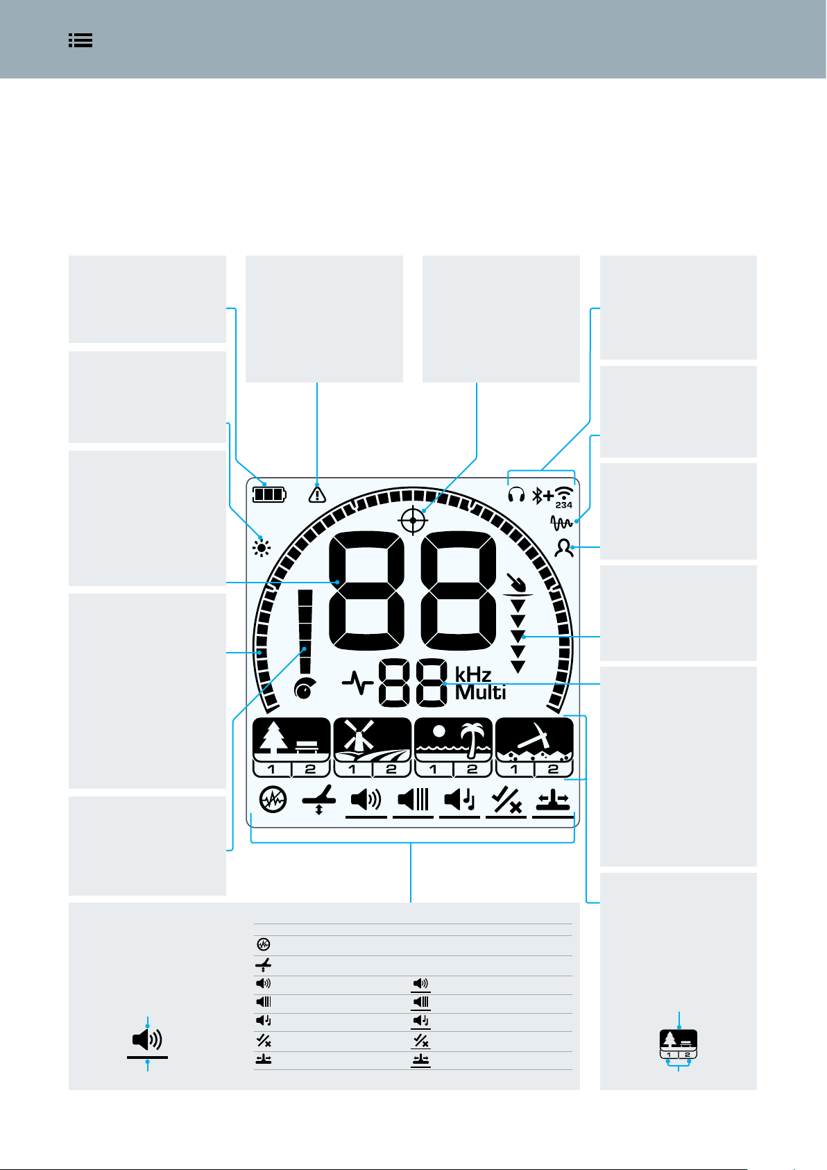
LCD Icons
All of the information you need to see during detecting and when adjusting your
detector settings is displayed on the large LCD in the control panel.
Battery Status Indicator
Displays the charge level of the
battery. (page 8)
Backlight
Appears when the backlight is
on. (page 32)
Target ID Display
Shows the Target ID of a
detected target. (page 30)
The Target ID Display also shows
the values of detector settings as
they are adjusted.
Discrimination Scale
High resolution 50 segment
(–9 to 40) Discrimination Scale
for accurate, stable target
identification. (page 30)
The Discrimination Scale
indicates target signal strength
when in Pinpoint. (page 36)
It is also used to adjust Tone
Regions for advanced audio
settings.
Sensitivity Indicator
Indicates approximate
Sensitivity level - 25 levels
shown in increments of 5.
(page 34)
Settings Menu
Settings and Advanced Settings
are in the Settings Menu.
(page 37)
Setting
Advanced Setting
Beach Overload Indicator
Indicates an automatically
reduced transmit signal
strength in order to prevent
overload in Beach Mode
in extreme conditions.
(page 25)
Setting Advanced Setting
Noise Cancel
Ground Balance
Volume Adjust Tone Volume
Threshold Level Threshold Pitch*
Target Tone Tone Pitch
Accept/Reject Tone Break
Recovery Speed Iron Bias
Pinpoint
Appears when Pinpoint is
active. (page 36)
Audio Connectivity
Displays the current wired
and wireless audio devices
connected to your detector.
(page 53)
Tracking Ground Balance
Appears when Tracking Ground
Balance is active. (page 40)
User Profile*
Appears when the saved User
Profile is active. (page 33)
Depth Gauge
Indicates the approximate
depth of a detected target.
(page 35)
Frequency Display
Shows the current operating
Frequency. (page 28)
The Frequency Display also
shows error codes and indicates
the selected Tone Region for
Advanced Settings.
Detect Modes
Displays the Detect Mode:
Park, Field, Beach, Gold*
Each Detect Mode has 2
customisable Search Profiles.
(page 22)
Detect Mode
Search Profiles
Page 11

Quick Start | 11Contents
Quick Start
EQUINOX is so easy to use, even a beginner can successfully begin detecting right out of
the box! There are just 4 easy steps to get started.
Before first use, it is recommended that you fully charge the battery for 4 hours (page 8).
Turn On
Press the Power button on the side of the control panel.
Select a Detect Mode
Select the optimum Detect Mode Search Profile for your detecting location.
(EQUINOX 800 shown).
See 'Detect Modes' on page 22 for more information on how to choose the
most suitable Detect Mode.
Noise Cancel
Select Noise Cancel from the Settings Menu, then press to initiate an
Auto Noise Cancel. This will take approximately 8 seconds to complete.
Begin Detecting!
Press to return to the Detect Screen, and begin detecting!
If excessive ground noise is heard
after performing the Quick Start
steps, carry out the Ground Balance
procedure (page 40).
If excessive noise is still being experienced
try adjusting the Sensitivity to a lower
level to reduce noise (page 34).
Page 12

Global and Local Settings | 12Contents
Global and Local Settings
When you are adjusting Settings and Advanced Settings, the icons of affected Detect
Modes will appear on the LCD.
Global Settings
Adjustments to some Settings
and Advanced Settings are
Global. All Detect Mode
Search Profiles will be affected by
changes to the setting.
Global Settings e.g. Volume; All Detect Modes and
Search Profile icons are on.
Semi-Global Settings
For Semi-global Settings and
Advanced Settings, Park Field,
and Beach Mode Search
Profiles all have the same setting, and
Gold Mode Search Profiles have
another.
Semi-Global Settings e.g. Threshold Level; The Detect
Modes and Search Profiles affected by changes are
on.
Local Settings
Adjustments to some Settings
and Advanced Settings are
Local. Only the active Detect
Mode Search Profile will be affected by
changes to the setting.
Local Settings e.g. Recovery Speed; Only the Detect
Mode Search Profile affected by changes is on.
Global and Local Settings Reference
Frequency Local
Noise Cancel Local
Ground Balance Local
Volume Adjust Global
Tone Volume Local
Threshold Level Semi-global
Threshold Pitch* Semi-global
Target Tone Local
Tone Pitch Local
Accept/Reject Local
Tone Break Local
Recovery Speed Local
Iron Bias Local
Sensitivity Global
Backlight Global
Reset a Search Profile
Individual Search Profiles can easily be returned to their factory
preset settings. Only the local settings will be reset; any global
settings will remain in their last-use state.
1. Navigate to the Detect Mode Search Profile you wish to reset.
2. Press and hold the Detect Mode button for 5 seconds.
3. The Mode icon will flash, 'SP' will appear on the Target ID
Display, indicating that the Search Profile has been reset.
'SP' will appear on the Target ID Display when a
Detect Mode Search Profile is reset.
4. Release the Detect Mode button. There will be a rising
confirmation tone.
Factory Reset the Detector
Factory Reset will return all detector settings and Detect Modes to
factory preset values, and will unpair all wireless headphones.
1. Turn the detector off.
2. Press and hold the Power button for approximately 8 seconds.
The start-up animation will display.
3. 'FP' will then appear on the Target ID Display, indicating that
Factory Presets are restored.
'FP' will appear on the Target ID Display when
Factory Presets are restored.
4. Release the Power button. There will be a rising confirmation
tone.
Page 13

Contents
Detecting Basics
This section contains great information for both new and experienced detectorists.
It explains basic detecting principles and techniques. You can learn how to set up your
detector for maximum comfort and ease of use.
Page 14

How Detectors Work | 14Contents
How Detectors Work
Metal detectors create an electromagnetic field which penetrates the ground. Metal
objects cause a change to this field because they conduct electricity. The detector senses
this change and sends a signal back to the control unit, alerting the operator.
Basic Principles
Metal detectors work by transmitting an electromagnetic field from the search coil into
the ground. Any metal objects (targets) within this electromagnetic field will become
energised, creating their own circular electric currents (eddy currents) and transmit an
electromagnetic field of their own. The detector’s search coil senses this receive signal and
alerts the user by producing a target response. Minelab metal detectors are also capable of
discriminating (or differentiating) between different target types and can be set to ignore
unwanted targets.
1. Battery (Inside handle)
The battery provides power to the detector.
8
2
1
3
2. Control Unit
This is where the transmit signal is
generated and the receive signal is
processed and converted into a target
response.
3. Search Coil
The detector’s search coil transmits the
electromagnetic field into the ground and
receives the return electromagnetic field
from a target.
4. Transmit Electromagnetic Field (blue)
The transmit (Tx) electromagnetic field
energises targets to enable them to be
detected.
5. Target
A target is any metal object that can
be detected by a metal detector. In this
example the detected target is treasure,
which is a good (accepted) target.
6. Unwanted Targets
Unwanted targets can be ferrous (iron),
such as nails, and can also be non-ferrous,
such as pull-tabs. If the metal detector is
set to reject unwanted targets then a target
response will not be produced for those
targets.
7. Receive Electromagnetic Field
(yellow)
The receive (Rx) electromagnetic field is
generated from energised targets and is
received by the search coil.
8. Target Response (green)
When a good (accepted) target is detected
the metal detector will produce an audible
response, such as a beep or a change
in tone, and a visual display of target
information will be shown on the screen.
4
6
5
7
Page 15

Key Detecting Concepts | 15Contents
Key Detecting Concepts
It is beneficial to understand a few key metal detecting technology principles so that you
can select the best settings for different detecting conditions.
For a complete glossary of detecting terms, visit www.minelab.com/knowledge-base/getting-started/glossary-of-terms.
Frequency
The operating frequency of a metal detector is one of the main
characteristics that determines how well targets can be detected.
The frequency of a detector is the number of times a signal is
transmitted into the ground per second, and is measured in Hertz
(Hz). 1000 Hz = 1 kHz.
EQUINOX is unique in that it offers both multi-frequency and single
frequency operation. Read 'Frequency' on page 28 for more
information.
Find out more about the EQUINOX Multi-IQ technology on
the Minelab Treasure Talk blog.
Ground Balance
Ground Balance is a variable setting that improves detection depth
by reducing noise in mineralised ground. Mineralised ground may
contain salts, e.g. wet beach sand, or fine iron particles, e.g. red soil.
These minerals respond to a detector’s transmit field in a similar
way that a target does. Due to the much larger mass of the ground
compared to a buried target, the effect of mineralisation can easily
mask small targets.
EQUINOX has different Detect Modes (Park, Field, Beach, Gold*) to
cope with typical ground conditions.
A Ground Balance setting is also available, read 'Ground Balance'
on page 40 for further information.
Detection Depth Factors
The most common question about metal detectors is “How deep do they go?”
The simple answer is “as deep as the diameter of the coil for a coin-sized target”. Therefore detectors with larger coils will detect deeper.
However, detection depth also depends upon detector technology and many environmental factors. A more complete answer is usually
more complex, and starts with “It depends...” The depth that a metal detector can detect a target depends on a number of factors:
Target Size
Large targets can be
detected deeper than
small targets.
Target Shape
Circular shapes (e.g.
coins and rings) can be
detected deeper than
long thin shapes (e.g.
nails or screws).
Target Orientation
A horizontal coin
(e.g. lying flat) can be
detected deeper than
a vertical coin (e.g.
standing on its edge).
Target Composition
Highly conductive
metals (e.g. silver) can
be detected deeper
than less conductive
metals (e.g. lead).
Ground Mineralisation
A target in benign
(unmineralised) ground
can be detected deeper
than a target in heavily
mineralised ground.
Page 16

Detecting Technique | 16Contents
Detecting Technique
Correct detecting technique is important to get the most out of your detector.
The techniques described will give you the best chance of success.
Holding the Detector
Insert your arm through the armrest and
armrest strap. Grasp the handle of the
detector and rest your forearm in the
armrest.
The correct position of the armrest should
allow you to comfortably grip the handle.
Your elbow should sit just above the back
of the armrest and the detector should feel
like an extension of your forearm.
Adjusting the Length of the Shafts
The lower shaft can be adjusted to several set lengths between
fully extended and fully retracted. Adjust the lower shaft to the
correct length and tighten the twist lock to hold it in place.
A correct shaft length will allow you to swing the coil over the
ground without uncomfortably stretching or stooping. If the coil is
too far from your body it will be difficult to balance and manoeuvre
while detecting. If the coil is too close to your body it may detect
your digging tools or any other metal which you are carrying,
causing confusing sounds.
Though the coil assembly is rigid and durable, sudden jolts or
bangs may cause random signals and inaccurate Target IDs, as well
as excessive wear and tear. Careful sweeping will ensure the coil
performs to an optimum level at all times.
Sweep Parallel to the Ground
You will obtain the best performance when the coil is swept close
and parallel to the ground at all times. This will maximise detection
depth and improve the response to small objects. Avoid excessive
brushing of the coil on the ground.
Overlap Your Sweep
Practice sweeping the coil over the ground in a side-to-side
motion while slowly walking forward at the end of each sweep.
Slightly overlap the previous sweep to ensure full ground coverage.
An average sweep speed is 2 to 3 seconds from right-to-left-toright.
Adjusting the Angle of the Coil
1. Loosen the yoke nut and bolt that fastens the lower shaft
to the coil. It should be loose enough to allow the coil to be
moved for adjustment, but tight enough that the coil can hold
its position.
2. While holding the detector in the detecting position, lightly
press the coil to the ground until it sits flat/parallel with the
ground. The coil should remain parallel when lifted to the
sweep height, approximately 25 mm (1-inch) above the
ground.
3. Tighten the yoke nut just enough to hold the coil in position.
Sweeping the Coil
EQUINOX Series detectors are motion detectors, meaning that
the coil must be moving across the ground in order to detect
a target. If the coil is held stationary over a target, it will not be
detected. The side-to-side detecting motion is called 'sweeping' or
'swinging', and with practice will become a comfortable and fast
way to cover ground.
Sweeping the coil incorrectly can cause you to miss targets or can
generate false signals.
Targets
Metal objects are referred to as targets. Targets are comprised
of ferrous and non-ferrous metals. Ferrous metals are those
containing iron such as steel, nails and some types of coins. Nonferrous metals are those which are not magnetic, such as gold,
silver, copper, bronze and aluminium.
You may wish to find a range of both ferrous and non-ferrous
targets.
Examples of Common Targets:
• Desired ferrous target – war artefact
• Undesired ferrous target – iron nail
• Desired non-ferrous target – gold coin
• Undesired non-ferrous target – pull-tab
Page 17

Detector Sounds | 17Contents
Detector Sounds
The EQUINOX produces a variety of different sounds for target and environmental signals
and various detector functions.
Targets
A target signal is the sound produced by the detector when any
metal object is detected.
Typically, a ferrous (iron) target gives a low tone response and
a non-ferrous target gives a higher tone response that varies
according to the conductive properties of the metal (e.g. silver will
give a higher tone than aluminium).
Volume and Target Proximity
Large targets and targets close to the ground-surface give louder
audio signals.
Signals produced by targets a long way from the coil are quiet,
becoming rapidly louder as the coil nears the target.
Deep Targets Shallow Targets
Quiet signal
No signal
The sound produced by the detector in Pinpoint or Ground
Balance will vary in volume and pitch depending on the signal
strength (from a target or ground mineralisation). This volume
range is proportional to the maximum volume setting.
Quiet signal
A large deep target signal will
be the same volume as a small
shallow target signal.
Loud signal
EMI can also be received from other metal detectors operating
nearby. Always detect a minimum of 15 metres (45-feet) away from
other detectors.
15 m (45")
EQUINOX should not be operated indoors. Metal in the
floors and walls, and household appliances will cause
significant noise interference.
Ground Noise
Ground interference (or ground noise) may occur when there are
high levels of mineralisation in the soil. This can be very common
in detecting locations, especially goldfields.
The effects of ground noise can be reduced using Ground Balance
(page 40).
Keypad
The detector will make a sound whenever buttons on the keypad
are pressed. A valid button press makes a short high pitched ‘bip’
sound. An invalid button press makes a low pitched beep.
Noise/False Signals
The detector may pick up unwanted noise signals, either through
the air or from the ground. These false signals can be reduced by
using Noise Cancel or Ground Balance. Turing down Sensitivity will
also allow you to operate the detector effectively in difficult (or
noisy) locations.
Electrical Noise
Electromagnetic Interference (EMI) may occur near power-lines,
phone towers or electric fences. This can cause a detector to
perform erratically, causing false signals and inaccurate Target ID.
The effects of electrical noise can be reduced using Noise Cancel
(page 39).
Threshold
The constant background ‘hum’ that can be produced by the
detector is called the Threshold. Some users like to hear a threshold
tone so that they can hear both target signals and rejected target
audio 'blanking'.
When a rejected target is detected, the Threshold ‘blanks’ (becomes
silent), indicating that a target is located underneath the coil, but
has been rejected by the discrimination pattern.
Detection (Audio signal)
Blanking (No Sound)
Threshold tone
Accepted target Rejected target
Page 18

Simple Detecting Exercise | 18Contents
Simple Detecting Exercise
Before attempting to find real targets, it is important to understand how to interpret the
audio and visual signals of the detector.
1. Gather a collection of different metal objects, e.g. various coins, gold and
silver jewellery, a nail, a pull-tab, a brass button and aluminium foil.
2. Take the detector outdoors, away from known sources of electromagnetic
interferences (EMI) and metal objects.
3. Lay the objects in a line, sufficiently spaced apart to allow the coil to pass
between them.
4. Sweep the coil across the test targets one at a time. Observe the Detect
Screen and listen to the sounds of the detector as it passes over each object.
The Detect Screen and audio response will give you detailed information
about the Target ID.
Don’t worry if the detector is not producing a sound over the nail — this is
because the detector begins in the default Park Mode Profile 1, which rejects
signals from common trash targets, including ferrous targets.
If you are getting signals from a clear patch of ground, there could be buried
metal objects. Try finding a different area.
You may like to make a record of the Target IDs for each of your targets.
When you go detecting, always carry a 'test target' with you, e.g. a coin,
which is similar to the targets you are looking for.
Bury it at around 4 – 6 inches within your detecting location and adjust your
EQUINOX settings until the desired response is heard over the test target.
This way you are guaranteed to detect the same types of targets if they are
there. Remember to dig up your test target after you are finished!
Nail or Screw Pull-Tab Tiny Coin Fine Gold Ring Large CoinSmall Coin Heavy Silver Chain
Page 19

Pinpointing Technique | 19Contents
Pinpointing Technique
A good pinpointing technique helps you to quickly narrow down the location of a
buried target, allowing you to determine its exact location before digging.
By combining a good pinpointing technique with the EQUINOX
Pinpoint function, you will be able to accurately locate a buried
target within an area before you dig.
For additional information on Pinpointing with the help
of the Pinpoint function, read 'Pinpoint' on page 36.
It is possible to pinpoint a target successfully without
using Pinpoint, however this requires practice.
Coil Configuration and Pinpointing
The standard EQUINOX Series EQX 11 detector coil has a wire
winding configuration know as Double-D.
When pinpointing, it is useful to know that a Double-D coil has
two overlapping wire windings in the shape of two D’s. The regions
created by the overlapping windings (running from the front
centre of the coil to the back) is the most sensitive area and will
give the loudest response when a target is directly beneath it.
The line shows the strongest signal zone
on the EQX 11 coil. This is also the same
for all EQX Double-D accessory coils.
Pinpointing a Target Manually
1. Sweep the coil slowly across the target location keeping the
coil parallel to the ground.
2. Locate the centre of the target by listening for the loudest
target signal response.
3. Make a mental note of the position, or mark a line on the soil
with your shoe or a digging tool.
4. Move to one side so that you can pass the coil over the target
at right angles to your initial direction.
5. Line up the target at 90° from the initial direction and repeat
the process. The object is located where the two imaginary
lines cross.
Beep!
Front view of the
Double-D strongest signal
profile.
The benefits of this configuration include lower noise susceptibility
(especially in mineralised ground), higher sensitivity, and a very
thorough search pattern requiring less sweep overlap.
Double-D coils may produce complex signals from
shallow targets. Sometimes three separate signals can
be heard for a single target as the coil is swept over it.
The strongest signal
occurs where the Tx and Rx
coil windings overlap.
2-3
Make a line where the strongest
signal is heard.
Beep!
4-5
Move 90° and repeat.
The intersection of the two lines marks the
exact location of the target.
Page 20

Target Recovery | 20Contents
Target Recovery
Using the right tools and a good target recovery technique is important to prevent
damage to a buried target, which could significantly reduce its value.
Digging Tools
Different detecting locations have different
types of ground, so you will need to take
the right tools with you. You may wish to
use a combination of tools when you dig
to speed up the recovery process.
Buy the best quality digging tools you can;
Purchase them from a detecting specialist,
as tools found in hardware stores can be
inadequate for recovering a target and vary
widely in quality.
You don’t want to be out on a detecting
trip with a broken digging tool!
Park
Field
Beach
Gold*
In Park locations, a digging knife with a serrated edge is great for cutting
through turf and fine roots to form a neat plug of earth. A small strong spade
is useful for digging bigger holes for deeper targets.
Field locations are often composed of dense clay soil that will clump
together. A small strong spade is useful for digging bigger holes for deeper
targets.
Typical sandy Beach locations mean targets can be easily recovered with
the use of a plastic scoop, or even your hands. A long handled sand scoop is
required for recovering submerged targets from the water.
In typical Gold locations, a small pick will help to break open the earth, while
a plastic scoop will assist with checking the soil for gold nuggets without
damaging them.
Recovering a Target
Be sure not to wear rings, bracelets or a watch, as they will produce a signal
when you are recovering targets.
A Minelab PRO-FIND Series pinpointer is another useful tool for quickly
narrowing down the location of a buried target within a hole.
1. Once a target has been pinpointed, clear the ground surface of loose material and
check the ground again for a signal. If there is no signal, then the target is amongst the
surface material. If the target is still in the ground, Pinpoint again.
2. Try to leave the ground exactly as you found it. Using a sharp tool, cut a neat plug,
leaving some grass attached on one side like a hinge. Lift the plug out and over. This
prevents soil from being scattered and allows the hole to be refilled quickly.
3. Check the hole for the target. If the target is not in the hole, place the detector on the
ground with the coil flat. Pick up a handful of soil and pass it over the coil, returning soil
to the hole after you have checked it. Repeat this procedure until the target is located.
4. Check that no other targets remain in the hole. Refill the hole with all soil and grass as
neatly as possible. Step lightly on the soil to compact it.
Leaving holes or a scarred area may result in action being taken to prevent the use of
metal detectors. Please ensure that the area of ground is left as you found it, and remove
all rubbish.
Page 21

Contents
Detect Modes
EQUINOX is equally adaptable for all target types and ground conditions… just select
your detecting location and go!
Detect Modes are based on common detecting locations, making it easy for anybody to
confidently choose the right Mode for their detecting session.
This section explains the differences between the Detect Modes, and includes some
great tips to help you master each Mode.
The Detect Mode descriptions in the following section are for typical detecting locations. Some Detect Modes will be useful in
locations not represented by the Mode name, icon, or description.
Page 22

Detect Modes | 22Contents
Detect Modes
EQUINOX Series redefines all-purpose detecting, with Detect Modes that are based on
common detecting locations. Simply select the best match and begin detecting.
EQUINOX Series features Detect Modes, each representing a
common detecting use: Park, Field, Beach, and Gold*.
Each Detect Mode has two Search Profiles.
Detect Mode
Search Profiles
Each Search Profile has been pre-configured to optimise the
detector for best performance in the conditions typical to that
location. Each of the pre-configured Profiles can be modified and
saved.
EQUINOX remembers its last-used Search Profile and will return to
this when the detector is turned on. For example, if Field Profile 1
was active when turned off, this Search Profile will be active when
the detector is turned back on.
Detect Mode Navigation
Detect Mode Search Profiles can be cycled through by
pressing the Detect Mode button.
Each press will scroll to the next Search Profile in a leftto-right direction. When the last Search Profile is reached, another
press of the Detect Mode button will return you to Park 1.
Adjusting Search Profiles
Save your favourite detecting settings in Profile 1 or 2 in each
Detect Mode once you are familiar with the detector.
Remember, some settings are global (page 12) and will be
adjusted for all Search Profiles when a change is made.
For the complete list of the factory presets for each Detect Mode
Search Profile, read 'Factory Presets' on page 63.
To Adjust a Search Profile:
1. Navigate to the Detect Mode Search Profile you wish to adjust.
2. Make the adjustments to the Settings and Advanced Settings
for that profile. They will be automatically saved.
3. Next time that Search Profile is selected, the local settings you
selected will be remembered.
If you want to restore the preset state of an individual Detect Mode
Search Profile, see 'Reset a Search Profile' on page 12.
To factory reset all detector settings and Detect Modes, see 'Factory
Reset the Detector' on page 12.
Choosing the Right Detect Mode
Choosing the right Detect Mode is important to get the best
performance for the environment you are detecting in. To easily
get started, choose Park, Field, Beach or Gold* to suit your location.
Park
Great for high-trash recreational
areas, including most general
detecting.
General / Coins Fine Jewellery Coins / Artefacts
Ideal for detecting in historical fields
for the widest range of target sizes.
Field
Fine Coins /
Artefacts
Search Profile 1 is suitable for general conditions. Search Profile
2 is optimised for more difficult conditions. Target sensitivity is
enhanced, but extra noise may also result.
Detailed descriptions of each Detect Mode are in the following
pages.
Beach
Optimised for all salty conditions –
dry sand, wet sand, surf, and
underwater.
Wet / Dry Sand
Underwater /
Surf
Best suited for gold nugget
prospecting in mineralised goldfield
Normal Ground Difficult Ground
Gold*
locations.
Page 23

Park | 23Contents
Park
Great for high-trash recreational areas, including most general detecting.
Park Mode is for searching in urban parks, or other recently inhabited sites where there may be coins and jewellery. There is often also lots
of common metal litter including aluminium foil, pull-tabs, bottle-caps etc. Park Mode is a good starting point for other general uses, such
as freshwater detecting, or use for artefact hunting by accepting all ferrous Target IDs.
Park Mode default settings will provide great depth, accurate target resolution and sufficient discrimination in trash-cluttered areas typical
of recreational parks. With Frequency set to Multi, Park Mode will be the most sensitive to a wide range of targets, while rejecting much of
the trash. If in doubt in a new area, or when first detecting, try Park mode first!
Park 1: General / Coins
Park 1 is optimised for modern coins and larger
jewellery with a default discrimination pattern set
to reject many common aluminium foil-like targets (Target ID 1).
Therefore this is the ideal profile to start with to learn EQUINOX,
before experimenting with the other Modes and more specialist
settings.
Park 1 Multi-IQ processes a lower frequency weighting of the
multi-frequency signal, as well as using algorithms that maximise
ground balancing for soil, to achieve the best signal to noise ratio.
Hence Park 1 is most suited for general detecting and coin hunting.
Park Detecting Hotspots
In order to maximise your detecting success, keep
an eye out for areas where people gather. These may
include park benches or under trees and other shady
spots where people have been sitting, or at recreation
grounds near clubrooms or spectator stands.
After festivals or events, there are often many objects
to find (especially coins that have been dropped), but
you may be in competition with other detectorists!
Always make sure you are allowed to detect in public
parks, recreation areas and private property.
Difficult Areas - Aluminium Foil
Reject Target IDs 1 and 2 in the
discrimination pattern for Park Mode
Search Profiles.
Park 2: Fine Jewellery
Park 2 is better suited for smaller targets and greater
trash densities. It will detect a wider range of targets
including low conductors (or higher frequency) targets, e.g. fine
jewellery. All non-ferrous targets are accepted by default. Recovery
Speed is also increased to clearly identify good targets masked by
iron trash.
Target Tone is set to 50 to allow greater audible target identification
rather than relying more heavily on the visual Target IDs. Park 2
Multi-IQ processes a higher frequency weighted multi-frequency
signal while ground balancing for soil.
Modern parks typically contain a high
amount of aluminium shards from discarded
trash (e.g. drink cans, pull tabs, ring pulls,
etc.) As aluminium is a non-ferrous very low
conductive target, its Target ID falls within
the same range as fine jewellery.
Park 1 is a good option in highly
contaminated parks. Rejecting Target IDs 1
and 2 (or higher if the unwanted aluminium
is larger in size) may also help with digging
less trash.
Page 24

Field | 24Contents
Field
Ideal for detecting in historical fields for the widest range of target sizes.
Field Mode is for searching open pasture, cropped or ploughed fields and historically occupied sites. These environments generally
contain ferrous trash and coke from previous human occupation. In highly infested sites, Field Mode is well suited for rejecting coke and
detecting hammered coins and ancient artefacts amongst the iron trash.
With Frequency set to Multi, Field Mode will be the most sensitive to the widest range of targets and more accurately identify objects at
the limits of detection depth, compared to all single frequency options.
Field 1: Coins / Artefacts
Field 1 is for general hunting with high trash
rejection. This assists in locating desired targets more
easily. The default discrimination pattern is set to reject Target IDs 1
and 2 (most coke signals).
The first Tone Break is set so that Target IDs 1 and 2 will produce
the same low tone as ferrous targets. Field 1 Multi-IQ processes a
lower frequency weighted multi-frequency signal, as well as using
algorithms that maximise ground balancing for soil, to achieve
the best signal to noise ratio. Hence being most suited for general
detecting and coin hunting.
Field Detecting Hotspots
When it comes to detecting for historical items, you
will want to find old inhabited sites that may have long
disappeared from view.
Research is a great way to find out where old sites
may have existed from old texts, maps, and articles.
This method of site selection can pay off and yield
wonderful results. Just search online for "metal detector
treasure" to see what is being discovered! Freshly
ploughed fields are also very good detecting locations,
as targets that were deep may have been churned to
the surface during ploughing.
Difficult Areas - Coke
Rejected Target IDs 1 and 2 in the
discrimination pattern for Field Mode
Search Profiles.
Field 2: Fine Coins / Artefacts
Field 2 suits locations with high target and trash
densities. It will better detect small hammered
coins on their edge or at greater depth. The default discrimination
pattern is set to reject Target IDs 1 and 2 (most coke signals).
Target Tone is set to 50 tones to enhance audio identification and
Recovery Speed is faster. The first Tone Break has been set so that
Target IDs 1 and 2 produce the same low tone as ferrous targets.
Field 2 Multi-IQ processes a higher frequency weighted multifrequency signal while ground balancing for soil.
Coke is the charcoal and carbon by-product
of burnt coal, and is prevalent around
historically populated areas.
Generally coke has a Target ID of 1 or 2. For
this reason it is rejected by default in Field
Mode. Note, this could result in some small
non-ferrous targets being missed.
Field 1 Multi-IQ, even with Target IDs 1 and
2 accepted, will reject more coke more than
Field 2 using Multi-IQ.
Page 25

Beach | 25Contents
Beach
Optimised for all salty conditions – dry sand, wet sand, surf, underwater.
Beach Mode is for salt water beaches including dry sand, wet sand, surf and underwater conditions. The salt that is typically present
causes the sand and water to be very conductive, causing salt noise to be detected. Multi-IQ is better able to reduce this noise than any
single-frequency can. Therefore Multi is the only Frequency option.
Beach Mode specifically identifies any residual salt response and assigns a ferrous Target ID - indicating that it's an unwanted target – so
that desirable low conductive targets (such as gold chains) can readily be detected with minimal interference from the salt water.
The Recovery Speed is relatively high to further reduce unwanted salt-water signals, without greatly sacrificing detection depth.
Beach 1: Wet / Dry Sand
Beach 1 is most useful for detecting in wet/
dry beach sand and also in shallow water where
conductive salt signals are prevalent. It has good sensitivity to
coins and small/large jewellery. Beach 1 reduces the salt signal,
while maintaining high transmit power, and still being sensitive
to desirable targets. Beach 1 Multi-IQ processes a low frequency
weighted multi-frequency signal, and uses special algorithms to
maximise ground balancing for salt.
Beach Detecting Hotspots
There are good chances of finding coins and jewellery
under jetties and board-walks, beside steps and entry
ways to and from the beach.
Locate the areas where people swim the most and
detect in the deeper water there. Venturing into
the water can give you an advantage over other
detectorists who remain on the sand. Research
shipwrecks if you are interested in historical finds.
Occasionally, the top layers of sand will be washed
away by stormy weather conditions, exposing some
deeper layers that often contain good targets.
Difficult Areas – Black Sand
The Beach Overload Indicator will appear
when the transmit signal strength is
automatically reduced.
Beach 2: Underwater / Surf
Beach 2 gives the best results when either wading
or shallow diving, with the coil and/or detector fully
submerged. In these instances, there is a very strong salt signal
present, so Beach 2 has a lower transmit power, which results in
much less noise. This profile may also be useful in dry conditions
where there are extremely high ground noise levels. Beach 2 MultiIQ processes a very low weighted multi-frequency combination,
using the same algorithms as Beach 1 to maximise ground
balancing for salt.
Some beaches contain black sand, which has
high natural iron content and is often
magnetic. This causes continuous false
ferrous detections, making normal beach
detecting impossible.
Beach Mode automatically senses black sand
and reduces the transmit power to ensure
that targets can still be detected without
overloading occurring. When black sand
is sensed, the Beach Overload Indicator
will appear on the LCD. When this icon
disappears, full transmit power automatically
resumes.
Page 26

Gold* | 26Contents
Gold*
Best suited for gold nugget prospecting in mineralised goldfield locations.
Gold Mode* is for gold nugget prospecting. Generally, gold nuggets are found in remote goldfields where targets are more sparsely
located.
Gold Mode* uses a special audio that has a continuous sound, with more subtle variation than the other Detect Modes. This audio signal
begins when the coil first approaches the target and then continues until the coil moves away. During the detection period, the signal
volume and pitch vary proportionally to the strength of the target signal.
Gold Mode is ideally suited to finding smaller surface gold nuggets (and some larger deeper ones) that are present in mineralised ground.
Gold 1: Normal Ground
Gold 1 is suitable for searching for small gold
nuggets in ‘mild’ ground. Most goldfield locations
have a variable level of iron mineralisation that will require an
ongoing Ground Balance adjustment, therefore Tracking Ground
Balance is the default setting. Target Tone is set to 1 and the audio
is optimised for hunting for gold nuggets.
Gold 1 Multi-IQ processes a high frequency weighted multifrequency signal, while ground balancing for mineralised soil.
Gold Detecting Hotspots
The best places to go detecting for gold nuggets are
where gold has previously been found. Surrounding
areas with very similar geology are also worth
exploring. Many government mining agencies publish
maps of goldfields locations and offer advice on
obtaining relevant fossicking or hobby prospecting
licences.
Some specific areas for gold prospecting include
tailings from goldmine sites, old diggings from the
1800s, in (and near) streams where gold panning is
carried out, arid dry-blowing locations and old reef
mine dumps and slopes.
Difficult Areas - Hot Rocks
Target IDs 1 and 2 often indicate low
conductive small gold nuggets. Hot rocks
are generally found in the ferrous range.
Gold 2: Difficult Ground
Gold 2 is best for searching for deeper gold nuggets
in ‘difficult’ ground conditions. Gold 2 has a lower
Recovery Speed, which will increase detection depth. However,
more ground noise in more heavily mineralised grounds may
result. Tracking Ground Balance is the default setting. Target Tone is
set to 1 and the audio is optimised for hunting for gold nuggets.
Gold 2 Multi-IQ processes a high frequency weighted multifrequency signal, while ground balancing for mineralised soil.
‘Hot’ rocks are commonly found in gold
prospecting locations. These are rocks that
Typically Small
Gold Nuggets
Typically Hot Rocks
are mineralised differently to the
surrounding ground. A highly mineralised
rock buried in mildly mineralised ground
would be considered to be a hot rock.
Hot rocks can easily be mistaken for gold
nuggets. The Target ID can assist here, with
hot rocks typically having a negative Target
ID number and gold having a positive ID in
the very low conductive range.
Page 27

Contents
Detect Screen Functions
The Detect Screen will be displayed while you are actively detecting. Key detecting
information can be viewed and adjusted on-the-go.
Detect Screen functions are the detector settings or status displays that are accessible
when you are in the Detect Screen.
Page 28

Frequency | 28Contents
Frequency
With EQUINOX you can operate across a wide spectrum of frequencies simultaneously
for maximum results, or you can operate in a single frequency.
EQUINOX Series detectors have simultaneous multi-frequency
capability with a technology called Multi-IQ, as well as a selection
of single frequencies.
Frequency adjustment is local; only the current Detect Mode
Search Profile will be affected by changes to this setting.
Changing the Frequency
The operating frequency is easily changed and has a dedicated
button on the control panel.
Press the Frequency button to advance to the next
available frequency. The Frequency will be shown on the
Frequency Display.
Displays a rectangle when operating in
Simultaneous Multi-Frequency.
For all Detect Modes, Multi is the recommended
Frequency setting.
Noise Cancel should be carried out whenever the
Frequency setting is changed.
Displays the current selected single
frequency in kHz: 5, 10, 15, 20*, or 40*.
Single Frequency Operation
Using a single frequency may have a slight advantage over multifrequency in certain detecting situations.
For example; if you were searching only for larger high conductive
targets located at great depth, using 5 kHz may give an advantage.
Similarly, if you were hunting only for very fine gold jewellery at a
shallow depth, then 20 kHz* or 40 kHz* may give better results in
some detecting environments, such as at a beach on the dry sand.
Frequencies and Detect Modes
The EQUINOX Detect Modes have different selections of Multi and
single frequencies. Each Detect Mode is limited to the frequencies
that will give the best performance for that mode. For example,
Park and Field can operate across every available frequency setting,
as good results can be achieved in any frequency.
Beach Mode however, can only perform successfully in typical
beach conditions in Multi, therefore single frequencies are not
available.
Similarly, Gold Mode* is optimised for detecting low conductive
gold nuggets that are more easily detected at higher frequencies.
Therefore the lower single frequencies (5 kHz, 10 kHz, and 15 kHz)
are not available.
EQUINOX600
Multi 5 kHz 10 kHz 15 kHz
Park
Field
Beach
EQUINOX800
Multi 5 kHz 10 kHz 15 kHz 20 kHz 40 kHz
Park
Field
Beach
Gold*
In some noisy environments (e.g. high Electromagnetic
Interference, where Noise Cancel is not fully effective), a single
frequency may pick up less noise than Multi will, however
maximum target sensitivity over a wide range of targets will be
reduced.
Page 29

SENSITIVITY
Frequency | 29Contents
Multi-IQ Technology
Multi-IQ is simultaneous multi-frequency detection and can be considered
as combining the performance advantages of both FBS and VFLEX in a new
fusion of technologies.
Multi-IQ achieves a high level of Target ID accuracy at depth much better
than any single frequency detector can achieve, including switchable single
frequency detectors that claim to be multi-frequency. When Minelab use
the term 'multi-frequency' we mean 'simultaneous' – i.e. more than one
frequency is transmitted, received and processed concurrently. This enables maximum target sensitivity across all target types and sizes,
while minimising ground noise (especially in saltwater).
The diagram is intended to be a simplified representation of how different frequencies of operation are better suited to different target
types; i.e. low frequencies (e.g. 5 kHz) are more responsive to high conductors (e.g. large silver targets) and high frequencies (e.g. 40 kHz*)
are more responsive to low conductors (e.g. small gold nuggets).
M
u
s
l
u
t
o
e
n
a
t
l
u
m
i
S
Q
I
-
i
t
l
u
M
HIGH
15 kHz
LOW
5 kHz 40 kHz
10 kHz
FREQUENCY
* 20 kHz and 40 kHz are not available as single operating frequencies in EQUINOX 600. The Multi-IQ frequency range shown applies to both EQUINOX 600 and 800. This diagram is
representative only. Actual sensitivity levels will depend upon target types and sizes, ground conditions and detector settings.
Visit the Minelab Treasure Talk Blog at www.minelab.com/tt-equinox for more information on EQUINOX technologies.
i
-
F
r
e
q
u
e
n
c
y
R
a
n
g
e
20 kHz
*
*
SMALL GOLDLARGE SILVER
Single Frequency Ranges
As well as operating with multi-frequency transmission, EQUINOX detectors
also have single frequency options where all of the transmitter power is
combined into one frequency for finding a specific type of target.
When selecting a detector with single frequency options, it is important to
consider not only the number of frequencies but also the frequency range.
A detector with more frequencies, but a smaller range will usually be less
versatile than a detector with fewer frequencies and a wider range.
It is also important to recognise that some frequency bands may have limited
value due to being widely used by communication agencies, making them
unavailable for consumer products, such as metal detectors.
EQUINOX 600 offers 3 single frequencies of 5 kHz, 10
kHz, 15 kHz in addition to Multi, giving a 3 times (×3)
range or ratio from 5 kHz to 15 kHz, hence the 3F×3
technology designation.
EQUINOX 800 offers 5 single frequencies of 5 kHz, 10
kHz, 15 kHz, 20 kHz, and 40 kHz in addition to Multi,
giving an expanded 8 times (×8) range or ratio from 5
kHz to 40 kHz.
Page 30

F
e
r
r
o
u
s
V
e
r
y
L
o
w
C
o
n
d
u
c
t
i
v
e
L
o
w
C
o
n
d
u
c
t
i
v
e
H
i
g
h
C
o
n
d
u
c
t
i
v
e
V
e
r
y
H
i
g
h
C
o
n
d
u
c
t
i
v
e
Target ID & Discrimination | 30Contents
Target ID & Discrimination
A detected target is shown as both a number and a segment on a scale. These indicate
its ferrous or non-ferrous properties for quick and easy identification.
Target ID
As the coil is swept over a target, the detector digitally processes
the target signal and represents the result as a number on the LCD.
Target ID is used to distinguish one type of metal target from
another. Target ID numbers range from –9 to 40.
Ferrous (iron) targets range from -9 to 0.
Non-ferrous targets range from 1 to 40.
The last detected Target ID remains on the LCD for five seconds
or until another target is detected. If there is no detection, or the
detector passes over a target that it rejects, the LCD will display
two dashes.
Record the Target IDs of the objects you find. Over
time, you will be able to create your own
discrimination patterns using this information, to make
your detecting sessions more productive.
Discrimination Scale
This circular scale corresponds to the 50 Target IDs, grouped
into 5 Regions. Accepted (detected) targets are shown as visible
segments. Rejected (non-detected or ‘blanked’) targets are turned
off.
Note: this is opposite to X-TERRA, Safari, E-TRAC and CTX 3030
detectors.
You can discriminate between desired and undesired targets that
appear along the Discrimination Scale. Therefore you only hear
target signals from those you want to find. Unwanted targets are
ignored.
You can do this by the following methods:
• Accepting/Rejecting detected targets upon detection using the
Accept/Reject button (page 49)
• Creating a discrimination pattern via the Accept/Reject setting
(page 49)
A Target ID of 32 indicates a non-ferrous,
high conductive target (e.g. a coin).
Discrimination
Scale
A grey icon
represents a flashing
icon on the LCD.
Target ID
Display
A Target ID of -3 indicates a ferrous target
(e.g. a nail).
When there is no detection, the Target ID
Display shows two dashes.
Page 31

Target ID & Discrimination | 31Contents
Typical Target Examples
While both the Target ID numbers and Discrimination Scale give a good representation of a target’s ferrous and non-ferrous properties,
desired and undesired targets can fall anywhere within the overall range from -9 to 40. Here are some common examples for good and
bad targets, showing the Tone Regions where they will likely be detected.
-9 to 0
Ferrous
Modern Canadian coins
Iron
Nails, Screws
‘Hot’ rocks
Coke
1 to 10
Very Low Conductive
2
5
1c
2c
Foil
Small
hammered coins
11 to 20
Low Conductive
13
5¢
16
12
2
5c
125c13
10c1620c1750c
Gold nuggetsTiny gold nuggets Larger gold nuggets
21
1¢
19
10c2120c
21
$1
$2
Bottle caps
21 to 30
High Conductive
25
10¢
22
50c
1
Copper SilverAluminium, Gold
25¢
31 to 40
Very High Conductive
29
30
$1
35
50¢
Large silver coins
This is intended as a starting guide only. Target IDs may vary from the examples shown, depending upon the actual target metal
composition, ground conditions and detector settings.
Target ID Accuracy
Multi-IQ technology gives greater Target ID accuracy and increased detecting performance, especially in heavily mineralised ground. In
benign ground, a single frequency may perform adequately, however depth and stable Target IDs will be limited by ground noise.
Multi-IQ simultaneous multi-frequency will achieve maximum depth with a very stable target signal. In mineralised ground, single
frequencies will not be able to effectively separate the target signal from the ground signal, giving decreased results. Multi-IQ will still
detect at depth, losing a minimal amount of Target ID accuracy.
Conventional Single
Frequency
20 to 33 Ferrous
Ferrous Not Detected26 27
Not Detected Not Detected27 20 to 33
Multi-IQ
Multi-Frequency
26 20 to 3326 26
26 26
Target ID AccuracyDepth
Conventional Single
Frequency
Target stability in mineralised soilTarget stability in benign soil
Multi-IQ
Multi-Frequency
Page 32

Backlight | 32Contents
Backlight
The EQUINOX LCD has a backlight for improved screen contrast in poor light conditions.
EQUINOX 600 has 2 backlight level settings, Off and High.
EQUINOX 800 has 4 backlight level settings, Off, High, Medium, and
Low.
The backlight is Off by default.
Backlight adjustment is global; all Detect Mode Search
Profiles will be affected by changes to this setting.
Continual use of the backlight, especially at full
brightness (High), will result in decreased battery
runtime.
Turning the Backlight On
Press the Backlight button on the top left of the control panel.
The backlight will illuminate at full brightness (High).
The Backlight icon will appear on the LCD when the
backlight is on.
The backlight setting will be remembered after the detector is
powered off. When the detector is turned on again, the backlight
will automatically return to its last-used state.
Adjusting the Backlight Brightness*
The EQUINOX 800 includes an adjustable backlight with four states:
Off, High, Medium, and Low.
1. Press the Backlight button on the left of the control panel. The
Backlight will illuminate at full brightness (High).
2. Each press of the Backlight button will reduce the Backlight
brightness by one level until the backlight is Off.
Page 33

User Profile* | 33Contents
User Prole*
EQUINOX 800 features an additional User Profile side button that saves a copy of the
current detector settings for future quick access.
User Profile stores the set values of all current local settings so that
you can access them instantly later.
The default settings for the User Profile are a copy of Park Mode Search
Profile 1.
Save a User Profile
1. Select the Detect Mode you wish to use as a basis for your User
Profile. Adjust the settings you wish to save.
2. Make sure you are in the Detect Screen, not the Settings Menu.
3. Press and hold the User Profile button on the right side of the
control panel.
4. The User Profile icon on the LCD will begin to flash rapidly. It
will then remain on and a rising confirmation tone will sound,
indicating that the User Profile has been saved.
You can save over the User Profile at any time by repeating the
above procedure.
Activating the User Profile
Press the User Profile button at any time to re-activate the saved
User Profile.
The User Profile icon will appear on the LCD when the User
Profile is active.
Any changes made to local settings when the User Profile is active
will be saved automatically.
To exit from the User Profile, press either the User Profile button
or the Detect Mode button. Settings will return to the last-used
Detect Mode Search Profile and the User Profile icon will turn off.
Page 34

Sensitivity | 34Contents
Sensitivity
EQUINOX is highly sensitive and has 25 Sensitivity levels. It is important to set the correct
Sensitivity level for your detecting conditions.
Sensitivity adjusts the detector’s level of response to targets and
the environment by controlling the amount of amplification
applied to signals received by the detector (sometimes called Rx
gain).
Targets are detected as distinct beeps that stop if the coil is held
stationary. Interference or noise usually sounds like a crackling
or popping, which generally continues when the coil is held
stationary.
The Sensitivity setting has a range from 1 to 25 with a default setting
of 20.
Sensitivity level adjustment is global; all Detect Mode Search
Profiles will be affected by changes to this setting.
Sensitivity Indicator
The Sensitivity Indicator on the EQUINOX LCD shows the
approximate sensitivity level in increments of 5.
Level 1-5 Level 6-10 Level 11-15 Level 16-20 Level 21-25
Recommended Sensitivity Settings
Some experimentation with the Sensitivity level may be required
for different detecting locations. For beginners, start with a low
setting and increase it progressively.
Decreasing the Sensitivity of the EQUINOX may reduce false signals
and interference. This will also improve differentiation between
signals caused by metal targets and those of soil mineralisation.
The following recommended settings will help get you started:
New user 20
Park or field with no trash 22
Park or field with trash 20
Salt water beach 20
Gold Mode 15-25
Experienced user 22-25
Difficult ground or noisy conditions 15-18
Detecting test targets indoors 1-10
Tiny ferrous trash targets might be detected when the Sensitivity is
set to a high level. The detector will also be affected by minerals in
certain soils and signals from electrical appliances.
Adjusting Sensitivity
Always choose the highest stable Sensitivity setting to ensure
optimum performance.
You can only adjust the Sensitivity level from the Detect Screen.
Before attempting to adjust Sensitivity, ensure that you are not in
the Settings Menu or in Pinpoint.
1. Holding the coil stationary, use the Plus (+) button to increase
the Sensitivity until false signals begin to occur.
2. Reduce the Sensitivity level by pressing the Minus (–) button,
just enough that these false signals disappear.
3. The exact Sensitivity Level will be shown on the Target ID
Display, and will disappear after 3 seconds of inactivity.
Page 35

Depth Gauge | 35Contents
Depth Gauge
The Depth Gauge indicates the approximate relative depth of a detected target.
The Depth Gauge is a guide only; fewer arrows indicate a shallower
target, more arrows indicate a deeper target. The accuracy can vary
depending on the target type and ground conditions.
The Depth Gauge has 5 levels in increments of approximately 50 mm
(2").
When there is no detection, the Depth Gauge icon and arrows are
off.
After a target is detected, the Depth Gauge will remain on the LCD
for up to 5 seconds, or until the next target is detected.
Here is an example of the Depth Gauge reading and the
approximate target depth for a US quarter detected in benign soil:
50mm
2"
100mm
4"
The depth gauge accuracy is reduced in highly
mineralised soil.
150mm
6"
200mm
8"
>200mm
>8"
Page 36

Pinpoint | 36Contents
Pinpoint
Switching to Pinpoint when you find a target activates the target signal strength
visualisation on the Discrimination Scale to help you accurately locate the buried target.
With Pinpoint enabled, the discrimination pattern is temporarily
disabled so that EQUINOX will detect all metals. Pinpoint also
switches off motion detection, so a target signal will be heard even
if the coil is stationary.
Pinpoint progressively masks the Target response by reducing
the Sensitivity with each sweep until only a very narrow target
response remains. This helps identify the exact location of the
target.
In Pinpoint, the detector's response indicates the strength of the
target signal directly below the coil. The Pinpoint audio response
is tone and volume modulated. The difference in tone and volume
will help to locate the position and depth of the target.
high
Tone
low
quiet
loud
Volume
quiet
This target will
produce a loud high
tone
This target will
produce a quiet low
tone
Pinpointing a Target
1. Press the Pinpoint/Detect button to enter Pinpoint.
The Pinpoint icon will appear at the top centre of
the LCD.
The Target ID of the detected target will remain on the Target
ID Display and the depth indicator will show its approximate
depth.
2. Sweep the coil slowly across the target location keeping the
coil parallel to the ground.
3. Taking note of the response, locate the centre of the target
by listening for the loudest signal and/or watching the
Discrimination Scale on the LCD.
4. When all of the segments on the Discrimination Scale are on,
the target will be below the centre of the coil.
If you have difficulty Pinpointing the target, press
Pinpoint/Detect again to take the detector out of
Pinpoint and then return to Step 1.
The detector may become noisy if left in Pinpoint. If this
occurs, return to normal detection then try Pinpoint again.
For more information on pinpointing technique, read 'Pinpointing
Technique' on page 19.
Pinpoint Visualisation
The Discrimination Scale on the LCD is used to represent the
proximity of a target to the centre of the coil.
As a target nears the centre of the coil, the signal volume
increases and becomes higher pitched, and the segments on the
Discrimination Scale begin to appear from the outside of the scale.
When all of the segments on the Discrimination Scale are on, the
target will be below the centre of the coil.
Page 37

Contents
Settings Menu
The Settings Menu contains many adjustable settings for improving performance.
You can adjust Noise Cancel, Ground Balance, Volume, Target Tones and more…
Page 38

Settings Menu | 38Contents
Settings Menu
The Settings Menu contains adjustable settings relating to the detector. You can change
audio and other detecting settings via this menu.
Settings
These top-level settings are the standard detecting adjustments
that control the performance of your detector.
Noise Cancel
Ground Balance
Volume Adjust
Threshold Level
Target Tone
Accept/Reject
Recovery Speed
Settings Menu Navigation
The Settings Menu can be accessed from any screen by
pressing the Settings button.
Each press of the Settings button will scroll to the next setting in
the Settings Menu in a left-to-right direction. After the last Setting
the detector returns to the Detect Screen. Press the Settings
button again to begin scrolling from the left again.
Pressing either the Detect Mode button or the Pinpoint/Detect
button from the Settings Menu will return you to the Detect
Screen.
The Settings Menu remembers the last accessed setting and will
return you to that setting the next time the Settings button is
pressed.
Advanced Settings
Advanced Settings give additional control to customise detector
audio and target signals. You have sound options to assist with
hearing even more information about detected targets from the
audio alone.
Advanced Settings are located in the Settings Menu, indicated by a
line beneath the top-level Setting icon.
Tone Volume
Threshold Pitch*
Tone Pitch
Tone Break
Iron Bias
Threshold Pitch is not available in the EQUINOX 600.
Accessing Advanced Settings
1. Navigate to any top level Setting that has an Advanced Setting
(e.g. Volume Adjust).
2. Press and hold the Settings button for 2 seconds. A line will
appear beneath the icon indicating you can now adjust the
Advanced Setting (e.g. Tone Volume). The screen will also
change to show the advanced values you can now adjust.
2 Seconds
3. Press and hold the Settings button for 2 seconds to return to
the top level setting.
The Settings Menu remembers if an Advanced Setting was last
accessed and will return you to that setting next time the Settings
button is pressed.
Page 39

Noise Cancel | 39Contents
Noise Cancel
Noise Cancel reduces the effect of environmental electromagnetic noise from sources
such as power lines, mobile phone towers, and other metal detectors.
Detectors may become noisy due to electrical interference from
power lines, electrical equipment or other detectors operating
close by. The detector interprets this interference as inconsistent,
erratic detections.
The Noise Cancel setting allows you to change the noise cancel
channel. This slightly shifts the detector transmit frequency to be
less responsive to the source of the noise.
Noise Cancel affects both the audible detection noise level and
pinpointing performance.
The Noise Cancel setting has 19 channels with a range from -9 to 9
with a default setting of 0 for all Detect Mode Search Profiles.
Noise Cancel adjustment is local; only the current Detect
Mode Search Profile will be affected by changes to this setting.
Auto is the recommended noise cancel method.
Noise Cancel should be carried out whenever the
frequency setting is changed.
Auto Noise Cancel
Manual Noise Cancel*
The Manual setting allows you to listen to each channel so you can
manually select the one with the least interference.
This can be useful when detecting in close proximity to other
detectors, or in locations with lots of electrical interference.
1. Hold the coil stationary and away from the ground.
2. Press the Settings button to navigate to the Noise Cancel
setting in the Settings Menu.
3. Press the Minus (–) or Plus (+) buttons to change the channel.
The channel is shown on the Target ID Display. Pause and
listen to the interference being received. Keep the detector still
during this process.
4. Once the channel with the least interference has been found,
press either the Detect Mode button or the Pinpoint/Detect
button to return to the Detect Screen.
5. The new Noise Cancel channel will be saved for the current
Search Profile.
Auto Noise Cancel automatically scans and listens to every
frequency channel and then selects the one with the least
interference.
1. Hold the coil stationary and away from the ground.
2. Press the Settings button to navigate to the Noise Cancel
setting in the Settings Menu.
3. Press the Accept/Reject button to initiate the Auto Noise
Cancel process.
Auto Noise Cancel can also be initiated on the EQUINOX 600 by
pressing the Minus (–) or Plus (+) buttons.
4. During the Auto Noise Cancel process the Discrimination Scale
will show the progress of the operation, and there will be a
series of ascending tones (approximately 8 seconds).
When this process is complete, the automatically selected
channel will appear on the Target ID Display and three
confirmation tones will sound.
5. Press either the Detect Mode button or the Pinpoint/Detect
button to return to the Detect Screen.
6. The new Noise Cancel channel will be saved for the current
Search Profile.
The current Noise Cancel channel is shown
on the Target ID Display. Press the Accept/
Reject button to initiate Auto Noise Cancel.
Auto Noise Cancel complete. The
automatically selected channel is shown
on the Target ID Display (e.g. 9)
The Target ID Display animates, and the
Discrimination Scale indicates progress.
Auto Noise Cancel
selects the
‘quietest’ signal
channel based on several
criteria. However,
sometimes this selected
channel may still have
some audible noise
present.
Page 40

Ground Balance | 40Contents
Ground Balance
Ground Balance reduces noise caused by ground mineralisation, allowing good targets
to be detected more clearly.
The Ground Balance setting calibrates the detector to the
local ground in order to eliminate the false signals caused by
mineralisation.
The Ground Balance setting has a range from -9 to 99, with a default of
0 for all Park, Field, and Beach Mode search profiles.
Tracking Ground Balance is the recommended and default ground
balance method for Gold Mode.
Ground Balance adjustment is local; only the current Detect
Mode Search Profile will be affected by changes to this setting.
Manual Ground Balance
Ground Balance can be manually adjusted until the minimum
amount of ground signal is heard.
1. Press the Settings button to navigate to the Ground Balance
setting in the Settings Menu.
2. Raise and lower the coil repeatedly over a clear patch of soil
that does not contain any targets.
Auto Ground Balance
With Auto Ground Balance, the detector automatically determines
the best Ground Balance setting after the balancing process is
initiated by the operator.
Using Auto Ground Balance is the recommended Ground Balance
Method.
1. Press the Settings button to navigate to the Ground Balance
setting in the Settings Menu.
2. Press and hold the Accept/Reject button throughout the Auto
Ground Balance process.
The Tracking Ground Balance icon on the LCD will
begin to flash rapidly.
3. Raise and lower the coil repeatedly over a clear patch of soil
that does not contain any targets. Observe the Ground Balance
value updating dynamically on the Target ID Display, as the
audio reduces in response to the ground.
4. The response will be stabilised when the value in the Target ID
Display settles on a single value.
5. Release the Accept/Reject button.
Listen to the audio response to interpret the result of the
Ground Balance; a low tone indicates that you should increase
the Ground Balance value and a high tone indicates that you
should decrease it.
3. Press the Minus (–) and Plus (+) buttons to manually change
the Ground Balance value until the minimum amount of
ground signal is heard. The Manual Ground Balance value is
shown on the Target ID Display.
The default Ground Balance setting of 0 is
recommended for Park, Field and Beach Modes
because these locations typically have less
mineralisation than goldfields.
However, if the ground is generating many noise signals (and/
or the Sensitivity level is set very low), then using Auto Ground
Balance is recommended.
If the Auto Ground Balance process does not greatly reduce
ground noise (due to highly mineralised ground or high salt
levels), then repeat the Auto Ground Balance process by
sweeping the coil from side-to-side, rather than the standard
up-and-down motion.
Page 41

Tracking Ground Balance
When Tracking Ground Balance is active, the detector continuously
adjusts the Ground Balance automatically during detecting. This
ensures that Ground Balance is always set correctly.
Tracking Ground Balance is the default and
recommended method for Gold Mode.
Tracking Ground Balance can also be useful when using Beach
Mode 2 underwater at the beach (in salt water).
The Tracking Ground Balance icon will appear on the LCD
when Tracking is active.
1. Press the Settings button to navigate to the Ground Balance
setting in the Settings Menu.
2. Press the Accept/Reject button to activate Tracking Ground
Balance. The Tracking icon will appear on the LCD.
Ground Balance | 41Contents
3. When you return to the Detect Screen, Ground Balance will
track automatically in the background, indicated by the
Tracking icon. The icon will remain on until Tracking Ground
Balance is turned off.
Turning Off Tracking Ground Balance
1. Press the Settings button to navigate to the Ground Balance
setting in the Settings Menu.
2. Press the Accept/Reject button to turn Tracking Ground
Balance off. The Tracking icon will disappear, and Manual
Ground Balance will be active.
Page 42

Volume Adjust | 42Contents
Volume Adjust
The Volume Adjust setting controls the level of all detector sounds to make them louder
or more quiet.
Volume Adjust changes the loudness of all detector audio,
including detection signals, the threshold tone, and confirmation
tones.
The Volume Adjust setting has a range from 0 (off ) to 25 with a default
setting of 20 for all Detect Mode Search Profiles.
When the volume level is set to 0, all audio is muted (off).
Volume Adjust changes are global; all Detect Mode Search
Profiles will be affected by changes to this setting.
Adjusting the Volume
1. Use the Settings button to navigate to the Volume Adjust
setting in the Settings Menu.
2. Use the Minus (–) or Plus (+) buttons to decrease or increase
the volume to a comfortable level, making sure that loud
signals (close or large targets) do not hurt your ears.
If you try to exceed maximum volume, there will be an invalid
button press tone.
Page 43

Tone Volume (Advanced Setting) | 43Contents
Tone Volume (Advanced Setting)
This Advanced Setting allows you to set a different volume level for each Tone Region.
This is a great feature when detecting in iron infested locations.
The volume of each tone associated with a Tone Region can be
adjusted.
The Tone Volume setting has a range from 0 (off ) to 25, with a default
setting of 12 for ferrous tones, and 25 for non-ferrous tones.
Tone Volume adjustment is local; only the current Detect
Mode Search Profile will be affected by changes to this setting.
The number of Tone Regions will vary depending on the
set value of the Target Tone setting. This allows you to
choose from 1, 2, 5 and 50 tones. Read 'Selecting the Number of
Target Tones' on page 46 for more information.
t2
t1
Tone Volume adjustment screen for Tone
Region 1 (t1), with a Target Tone setting of
2; The Discrimination Scale is divided into
2 regions.
Tone Volume adjustment screen for Tone
Region 1 (t1), with a Target Tone setting of
5; The Discrimination Scale is divided into
5 regions.
t3
t2
t1
t4
t5
Adjusting Tone Volume
1. Use the Settings button to navigate to the Volume Adjust setting in the Settings Menu.
2. Press and hold the Settings button for 2 seconds. A line will appear beneath the icon indicating
that the Tone Volume Advanced Setting has been selected.
3. The Frequency Display will indicate the Tone Region that is currently selected (e.g. t1) and the Tone
Region segments on the Discrimination Scale will be on. Press the Minus (–) or Plus (+) buttons to
adjust the volume of the selected Tone Region.
4. Press the Accept/Reject button again to advance to the next Tone Region (i.e. t2). 1, 2, or 5 Tone
Regions can be adjusted depending on the selected Target Tone setting.
Only the ferrous tone (t1) can be adjusted on the EQUINOX 600.
5. Repeat until all Tone Regions have been adjusted.
6. A long press of the Settings button will return you to the Volume Adjust setting.
In trash or iron infested locations, set the Tone Volume of the ferrous Tone Region to zero
and increase the volume of the Tone Regions where your preferred targets will appear.
You will not hear undesired ferrous targets and highly desired high conductive targets signals will
be emphasised, by giving the loudest target response.
Other non-ferrous targets that are not within the preferred target Tone Region will be still be
heard, but will be quieter.
When adjusting the Tone
Volume setting, press the
Accept/Reject button to
advance to the next Tone
Region. (5 tones shown)
Page 44

Threshold Level | 44Contents
Threshold Level
Threshold is the constant background sound that can be produced by the detector.
Threshold is a useful setting for distinguishing between desirable
and undesirable targets, as well as hearing faint gold nugget signal
responses.
The Threshold Level setting has a range from 0 to 25 with a default
setting of 0 (off) for Park, Field, and Beach Modes, and a default setting
of 12 for Gold Mode*.
Threshold Level changes are semi-global; Park, Field, and
Beach Mode Search Profiles will be affected by changes to this
setting when in any of these modes.
Gold Mode* Threshold Level is controlled separately to the other modes.
Adjusting the Threshold Level
The Threshold Level Setting for all Detect Modes is adjusted in the
same way.
1. Use the Settings button to navigate to the Threshold Level
setting in the Settings Menu.
2. Press the Minus (–) or Plus (+) buttons to adjust the Threshold
Level. Adjustment takes effect immediately, so listen to the
audio to select your preferred level.
With the EQUINOX 800, the pitch of the Threshold tone can be
set higher or lower via the Threshold Pitch Advanced Setting
(page 45).
Threshold Blanking
Detection (Audio signal)
When a rejected target is
detected, the Threshold tone
‘blanks’ (becomes silent) to
indicate that a rejected target is
Threshold tone
Accepted
target
underneath the coil.
If the Threshold is set to 0, you
will not hear the blanking of
the rejected targets.
Blanking (No Sound)
Threshold tone
Rejected
target
Park, Field, and Beach Threshold
Park, Field, and Beach Modes use a simplified type of threshold
tone, i.e. a 'reference' threshold. It is a continuous background
tone that will blank when a rejected target is detected. Without a
reference threshold, a rejected target detection would be silent,
and you would not be made aware of the target's existence.
For typical treasure detecting locations where there is often a large
amount of trash in the ground, constant audio blanking may be
disruptive.
Minelab recommends using a Threshold Level setting of 0 (off ) for
Park, Field and Beach applications, unless you want to hear audio
blanking.
Gold Threshold
The Threshold for Gold Mode is a 'true' threshold tone that can be adjusted to improve the audibility of faint signals from small gold
nuggets. Unlike a 'reference' Threshold, 'true' Threshold allows gold nugget signals to be emphasised in typically mineralised 'noisy'
goldfield soils. Greater control of the target audio response may be achieved by adjusting the Threshold and Volume settings together.
Threshold Level
Audio range that
you are able to hear
Quiet signal
Too High
If the Threshold Level is too high, faint targets will be harder
to hear above the Threshold hum.
masked
Loud signal
just audible
Audio range that
you are able to hear
Threshold Level
Too Low
If the Threshold Level is too low, the slight variation caused
by a small or deep target may not be sufficient to hear.
Adjusting the level to below an audible level will ensure
silent operation but could mask the audio response from
small or deep targets.
Quiet signal
now inaudible
Loud signal
Audio range that
you are able to hear
Threshold Level
Quiet
Just Right
Adjust the Threshold Level to a faint audible hum. This
will emphasise variations in signal response which may
indicate the presence of a target. If the soil conditions
change, the Threshold Level may need further adjustment.
signal
Very loud
signal
Page 45

Threshold Pitch* (Advanced Setting) | 45Contents
Threshold Pitch* (Advanced Setting)
This EQUINOX 800 Advanced Setting allows you to set the threshold tone to be higher or
lower pitched. Set the level to the most comfortable pitch for your hearing.
Threshold Pitch allows you to adjust the audio pitch of the
Threshold tone. Hearing will vary between individuals, so adjust
the Threshold Pitch to a level that is comfortable for your hearing.
The Threshold Pitch setting has a range from 1 to 25 with a
default setting of 4 for Park, Field, and Beach Modes, and a
default of 11 for Gold Mode.
Threshold Pitch changes are semi-global; Park, Field, and Beach Mode
Search Profiles will be affected by changes to this Advanced Setting
when in any of these modes. Gold Mode* Threshold Pitch is adjusted
separately to the other modes.
Adjusting the Threshold Pitch
1. Use the Settings button to navigate to Threshold Level in the
Settings Menu.
2. Press and hold the Settings button for 2 seconds. A line will
appear beneath the Threshold Level icon indicating you have
selected the Threshold Pitch setting, and 'Pt' will appear on the
Frequency Display.
3. Press Plus (+) to set the threshold tone to a higher pitch.
Press Minus (–) to set threshold tone to a lower pitch. Any
adjustments are automatically saved.
4. A long press of the Settings button will return you to the
Threshold Level setting.
Threshold Pitch adjustment screen - Park,
Field, and Beach Modes.
Threshold Pitch adjustment screen - Gold
Mode.
Page 46

Target Tone | 46Contents
Target Tone
The Target Tone Setting controls the number of different tones you will hear for different
types of targets and the number of adjustable Tone Regions for Advanced Settings.
Target Tone allows you to divide the Target ID range
into separate Tone Regions. Therefore, you can hear
more or less target information.
The Target Tone setting has the options of 1, 2, 5 and 50.
Target Tone adjustment is local; only the current
Detect Mode Search Profile will be affected by
changes to this setting.
Gold Mode* has a Target Tone setting of 1 only, and
cannot be changed.
Selecting the Number of Target
Tones
1. Use the Settings button to navigate to Target Tone
in the Settings Menu.
2. Use the Minus (–) and Plus (+) buttons to select the
number of audio tones of 1, 2, 5 or 50.
Default Target Tone settings:
Search Profile Default Setting
Park 1
Park 2
Field 1
Field 2
Beach 1
Beach 2
Gold 1*
Gold 2*
5
50
2
50
5
5
1
1
Examples showing the default Tone Region end positions for Park Mode.
1 Tone: There is 1 tone region (t1)
All detection tones have the same pitch.
2 Tones: The Discrimination Scale is
divided into 2 Tone Regions.
By default this is at the ferrous/nonferrous division, however this point can
be adjusted. Ferrous tones signals have
one pitch and non-ferrous signal have a
different pitch.
5 Tones: The Discrimination Scale is
divided into 5 Tone Regions.
By default this is at (or near) each division
guide on the Discrimination Scale. Each of
the Tone Regions has a different pitch.
50 Tones: The Discrimination Scale is
divided into 2 Tone Regions.
By default this is at the ferrous/nonferrous division, however this point can be
adjusted. The Ferrous Tone Region has a
narrow range of lower pitched tones. The
non-ferrous Tone Region has a wider range
of higher pitched tones.
t1
t2
t1
t3
t2
t1
t1
t4
t2
t5
Target Tone Dependencies
When the Target Tone setting is changed, the options in the Advanced Settings of Tone Volume, Tone
Pitch, and Tone Break also change.
These Tone Regions can then have their Pitch, Volume, and Tone Region end positions controlled
individually.
Page 47

Tone Pitch (Advanced Setting) | 47Contents
Tone Pitch (Advanced Setting)
This Advanced Setting allows you to adjust the pitch of target responses for specific
types of targets. This makes it easier to hear your preferred targets.
The pitch of each Tone Region can be adjusted. This may be useful
to help differentiate between common targets with similar Target
IDs.
The Tone Pitch setting has a range from 1 to 25.
Tone Pitch adjustment is local; only the current Detect Mode
Search Profile will be affected by changes to this Advanced
Setting.
Tone Pitch is not available in Gold Mode*.
EQUINOX 600 allows only the first Tone Pitch to be adjusted.
EQUINOX 800 allows all Tone Pitches to be adjusted.
Adjusting Tone Pitch: 1, 2, or 5 Tones
1. Use the Settings button to navigate to Target Tone in the
Settings Menu.
2. Press and hold the Settings button for 2 seconds. A line will
appear beneath the Target Tone icon indicating you have
selected the Tone Pitch setting.
3. Press Plus (+) to set the Target Tone to a higher pitch. Press
Minus (–) to set the Target Tone to a lower pitch.
Tone Pitch Default Settings
Depending on the set number of Target Tones, there are different
default Tone Pitch settings for each Tone Region. These can be
adjusted to different values at any time.
Number of Tones Default Setting
1 11
2 1, 20
5 1, 6, 12, 18, 25
50 1, 20
4. To advance to adjusting the pitch of the next Tone Region (i.e.
t2), press the Accept/Reject button.
If the Target Tone setting is set to a value of 1, there will only be 1
Tone Region (t1).
5. A long press of the Settings button will return you to the Target
Tone setting.
When adjusting the Tone Pitch
Advanced Setting, press the
Accept/Reject button to advance
to the next Tone Region.
Page 48

Adjusting Tone Pitch: 50 Tones
When a Target Tone setting of 50 is selected for a Search
Profile, the Tone Pitch Advanced Setting behaves
differently.
To provide greater audio separation between ferrous and
non-ferrous targets, a deliberate gap can be set between
the highest possible pitch of the ferrous tones, and the
lowest possible pitch of the non-ferrous tones.
Therefore a non-ferrous target with a Target ID very close
to the ferrous range will sound much higher pitched and
therefore easy to distinguish as non-ferrous from the audio
signal alone.
Adjust the Tone Pitch of 50 tones in the same way as
adjusting the Tone Pitch of 1, 2 and 5 tones (page 47).
The non-ferrous setting cannot be a higher number than
the ferrous setting.
The example below shows how 'masking' sections of the
full pitch range makes it easier to hear a clear difference
between ferrous and non-ferrous targets.
t1: 50 Hz
range
t1: 50 Hz
range
Tone Pitch (Advanced Setting) | 48Contents
t2: 500 Hz
range
t2: 500 Hz
range
The Tone Pitch setting of
1, 24 represented on the
Discrimination Scale when the
Tone Break setting is -5.
The 500 Hz non-ferrous tone
range is spread across Tone
Region 2 (t2), and the 50 Hz
ferrous tone range is spread
across Tone Region 1 (t1).
This shows the same Tone pitch
setting, but a higher Tone Break
setting of 10.
This means that the 500 Hz high
tones becomes compressed into
fewer Target IDs, and the 50 Hz
low tones are stretched across
more Target IDs.
Default Tone Pitch Gap
(1, 20)
Ferrous targets will be very low
pitched. Non-ferrous targets
will sound distinctly higher
pitched than a ferrous target
with a similar Target ID.
Maximum Tone Pitch Gap
(1, 25)
A greater difference in Pitch
between ferrous and nonferrous targets gives very easy
differentiation.
Small Tone Pitch Gap
(11, 12)
No clear difference in pitch
between ferrous and nonferrous targets. They may be
indistinguishable from audio
alone.
t1 has a fixed narrow pitch
range width of 50 Hz
5 10
Tone Pitch setting adjustment range
5 10 15 20
Highest PitchLowest Pitch Full Pitch Range
t2 has a fixed wider pitch range width of 500 Hz
1 to 25
251 5 20
Page 49

Accept/Reject | 49Contents
Accept/Reject
You can create your own discrimination patterns to detect or ignore specific target types,
so you can dig more treasure and less trash.
Targets are represented by both a Target ID number and an
individual segment on the Discrimination Scale (page 30).
Target ID segments can be turned on or off to either detect
(accept) or ignore (reject) targets. All Target IDs that are on will be
accepted and all Target IDs that are off will be rejected.
The combinations of accepted and rejected segments are referred
to as discrimination patterns.
The Discrimination Scale has a range from -9 to 40.
Discrimination patterns are local, only the active Detect Mode
Search Profile will be affected by changes to the pattern.
Creating a Discrimination Pattern
1. Use the Settings button to navigate to Accept/Reject in the
Settings Menu.
2. Navigate to the Target ID you wish to change, using the
Minus (–) and Plus (+) buttons. The Plus button will move one
segment in a clockwise direction with each press. The Minus
button will move one segment anti-clockwise with each press.
The current selected Target ID will flash slowly, and the
corresponding Target ID number will appear on the Target ID
Display.
3.
4. Continue to navigate around the Discrimination Scale, turning
Press the Accept/Reject button to turn the Target ID on
or off. A Target ID will be detected if the Target ID
segment is on.
Target IDs on or off with the Accept/Reject button until you
have created your discrimination pattern.
Accepting/Rejecting Detected Targets
A target can be rejected upon detection if the corresponding
Target ID is currently turned on in the discrimination pattern.
If a Target ID is currently accepted and a detection occurs, an audio
response will be heard, the Target ID segment will flash, and the
Target ID number will appear on the Target ID Display.
To reject the detected
target, press the Accept/
Reject button.
An accepted non-ferrous target with a
Target ID of 32 is detected. Segment 32 on
the Discrimination Scale will flash.
Targets with that Target ID will now be rejected, and will not be
heard.
The last rejected target can be instantly re-accepted by pressing
the Accept/Reject button again, as long as no other detection
occurs before doing so.
Accepting a rejected Target ID is not possible directly from the
Detect Screen. Rejected Target IDs must be re-accepted by
adjusting the discrimination pattern via the Accept/Reject Setting
in the Settings Menu.
All-Metal
Turn All Metal on by pressing the All-Metal
button on the control panel.
This disables the current discrimination pattern so that
all metal objects will be detected.
Press the All-Metal button again to turn the
discrimination pattern back on.
All-Metal is off by default each time the detector is
turned on.
Discrimination pattern active
All-Metal active - All Discrimination Scale
segments are on.
Page 50

Tone Break (Advanced Setting) | 50Contents
Tone Break (Advanced Setting)
This Advanced Setting allows you to move the end position of each Tone Region.
Very low conductive non-ferrous targets in varying ground
conditions may be detected within the ferrous Target ID range.
The Tone Break setting allows you to move the point at which
ferrous tones occur. For example, you may want ferrous tones to
occur for any target with a Target ID from -9 to 2. Using the Tone
Break setting, you can move the ferrous tone end position up to
2. This moves some non-ferrous targets into the ferrous range,
however you will now also ignore many of the 'bad' ferrous targets.
You can also adjust the end positions of other Tone Regions to gain
greater distinction between targets of varying conductivity levels.
Target IDs -9 to 0 are set as ferrous by default for Park and Beach
Modes, and -9 to 2 for are set as ferrous by default for Field Mode.
Tone Break adjustment is local; only the current Detect Mode
Search Profile will be affected by changes to this Advanced
Setting.
Tone Break is not available in Gold Mode*, or when the Target Tone
setting is 1.
Adjusting Tone Break
EQUINOX 600 allows only the ferrous Tone Break position (t1) to be
adjusted. EQUINOX 800 allows 4 Tone Break positions (t1, t2, t3, t4)
to be adjusted.
1. Use the Settings button to navigate to Accept/Reject in the
Settings Menu.
The Tone Region currently selected will be displayed on the
Frequency Display (e.g. t1). The Target ID Display will show the
current value of the Tone Region end point, (e.g. 0), and the
corresponding Target ID segment will flash slowly.
3. Navigate to the Target ID segment you want to use as the end
position; Press the Plus (+) button to move the end position
one segment in a clockwise direction. Press the Minus (–)
button to move it one segment anti-clockwise.
4. To advance to adjusting the next Tone Region end position (i.e.
t2), press the Accept/Reject button.
Note that the last Tone Region end position cannot be
adjusted because the end position is always 40.
5. A long press of the Settings button will return you to the top
level setting.
Tone Break Default Settings
Depending on the number of Target Tones selected, each mode
has different presets. These can be adjusted.
Number of Tones Park | Beach Field
2 0 2
5 0, 10, 20, 30 2, 10, 20, 30
50 0
(1 adjustment position)
2
(1 adjustment position)
2. Press and hold the Settings button for 2 seconds. A line will
appear beneath the Accept/Reject icon, indicating that you
have selected the Tone Break setting.
Examples of the Tone Break adjustment screen when the Target Tone setting is 5.
× 3
Tone Break adjustment screen showing the
default Tone Break end point for t1: 0.
Tone Break end point for t1 adjusted to -3.
Press Accept/Reject to advance to the next
Tone Break, t2.
Page 51

Recovery Speed | 51Contents
Recovery Speed
The Recovery Speed setting alters how quickly the detector responds from detecting
one target to detecting another target.
By increasing the Recovery Speed, the detector is able to better
differentiate between multiple targets that are close together.
This assists in high-trash areas with finding smaller desired targets
amongst larger iron trash.
EQUINOX 600 has 3 Target Recovery Speeds, and EQUINOX 800 has 8
recovery speeds.
Recovery Speed adjustment is local; only the current Detect
Mode Search Profile will be affected by changes to this setting.
While using a higher target Recovery Speed may increase the
ability of the detector to find difficult targets, it also results in
reduced Target ID accuracy and less detection depth.
Low Recovery Speed
Medium Recovery Speed
'Good' non-ferrous target
response is masked by the
'bad' ferrous target response.
'Good' non-ferrous target
response is partially masked
by the 'bad' ferrous target
response.
Adjusting Recovery Speed
When adjusting the Recovery Speed for the first time, lay out
some overlapping targets to test how the detector responds with
different Recovery Speed settings.
1. Use the Settings button to navigate to Recovery Speed in the
Settings Menu.
2. Press the Minus (–) and Plus (+) buttons to decrease or increase
the Recovery Speed. Adjustments are automatically saved.
EQUINOX600/800 Equivalent Recovery Speeds
The following shows the equivalent recovery speeds between the
two models. EQUINOX 600 offers fewer adjustment increments and
a slower maximum Recovery Speed than the 800 model.
EQUINOX 800
EQUINOX 600
Default Recovery Speed Settings:
Detect Mode EQUINOX600 EQUINOX800
Park 1
Park 2
Field 1
Field 2
Beach 1
Beach 2
Gold 1*
Gold 2*
1 2 3 4 5 6 7 8
1 2 3
3
3
3
3
2
3
—
—
5
6
6
7
6
6
6
4
High Recovery Speed
Both target responses can be
clearly heard
Swing Rate
A good general swing rate is around 2-3 seconds from right-toleft-to-right. A higher Recovery Speed generally allows for a faster
swing rate with less likelihood of missing targets.
A higher Recovery Speed, for the same swing rate, will help to
reject ground noise, but also decrease detection depth. A lower
Recovery Speed, for the same swing rate, will increase detection
depth, but may increase noise.
If you are experiencing high levels of ground noise
at the beach, or when detecting underwater,
try increasing the Recovery Speed to reduce
the noise. It is also possible to vary both
swing rate and Recovery Speed to help
minimise ground noise.
Page 52

Iron Bias (Advanced Setting) | 52Contents
Iron Bias (Advanced Setting)
The Iron Bias setting adjusts the likelihood of the detector to identify a target as iron if it
presents both ferrous and non-ferrous signals.
All ferrous targets produce a combination of a ferrous and nonferrous response. Large ferrous targets can even present a stronger
non-ferrous response. Also, a ferrous target adjacent to a nonferrous target can produce a similar response.
The Iron Bias Setting provides some control over the Target ID
response. A lower Iron Bias setting will allow the natural response
to dominate which means that the target is more likely to be
classified as a non-ferrous target. A higher setting will increase the
likelihood that the target is classified as iron.
The Iron Bias setting has a range from 0 to 9.
Iron Bias is only available when the operating frequency is Multi.
Iron Bias adjustment is local; only the current Detect Mode
Search Profile will be affected by changes to this Advanced
Setting.
In environments with dense iron trash, a higher Iron Bias is
recommended in order to mask them. In areas where you do not
want to miss any non-ferrous targets amongst iron trash, a lower
setting is recommended. This will cause more ferrous targets to be
detected and identified as desirable non-ferrous targets.
Adjusting Iron Bias
EQUINOX600/800 Iron Bias Setting Equivalents
The following shows the equivalent Iron Bias settings between the
two models. EQUINOX 600 offers fewer adjustment increments and
a lower maximum Iron Bias than the 800 model.
EQUINOX 800
EQUINOX 600
1 90 2 3 4 5 6 7 8
0 2 3
1
Default Iron Bias Settings:
Detect Mode EQUINOX600 EQUINOX800
Park 1
Park 2
Field 1
Field 2
Beach 1
Beach 2
Gold 1*
Gold 2*
2
0
0
0
2
2
—
—
6
0
0
0
6
6
6
6
1. Use the Settings button to navigate to Recovery Speed in the
Settings Menu.
2. Press and hold the Settings button for 2 seconds. A line will
appear beneath the Recovery Speed icon, indicating you
have selected the Iron Bias setting, and 'FE' will appear on the
Frequency Display.
3. Press the Minus (–) and Plus (+) buttons to decrease or increase
the Iron Bias. Adjustments are automatically saved.
4. A long press of the Settings button will return you to the
Recovery Speed setting.
The Iron Bias adjustment screen.
Page 53

Contents
Detector Audio
EQUINOX Series detectors have many audio options to suit any preference and detecting
situation.
Wireless headphones can be used with the EQUINOX Series. EQUINOX is compatible with
Bluetooth® aptX™ Low Latency and Minelab's super-fast Wi-Stream audio technology.
Page 54

Audio Options
EQUINOX has both wired and wireless audio options to choose from.
There is a range of audio accessories
available. EQUINOX is also compatible with
most readily available headphones.
Wireless Audio Wired Headphones
ML 80 and other Wireless
Bluetooth® aptX™ Low Latency
headphones
Audio Options | 54Contents
Speaker
3.5 mm (1/8-inch) headphones
WM 08 Wireless Audio Module
3.5 mm (1/8-inch) headphones required
Other Bluetooth® headphones
6.35 mm (¼-inch) headphones
Adaptor required
Waterproof headphones
Minelab 3.5 mm (1/8-inch)
Wireless Audio Latency
Each EQUINOX compatible wireless technology has a slightly different latency, or delay.
When metal detecting, the lowest latency is best.
When the coil is moving across the ground, any delay (latency) of the audio signal means that the coil will have moved past the target that
produced that audio. Low latency (less audio delay) causes targets to be detected closer to where they really lie in the ground. This is very
evident when swinging a coil left and right across a target. A higher latency will mean that the target is perceived to be in two locations
either side of the actual location. A lower latency will minimise this effect.
Wireless Audio can not be used if the control unit is submerged. EQUINOX waterproof wired headphones are required for
underwater detecting. Submerging the coil only will not affect wireless audio operation.
Wi-Stream Technology
Wi-Stream uses efficient low-power
digital audio transmission to achieve the
non-perceivable audio time lag of 17 ms
between EQUINOX and the WM 08 Wireless
Module.
For the fastest possible wireless audio, use
the WM 08 Wireless Audio Module*.
aptX™ Low Latency Technology
aptX™ Low Latency technology is faster
than standard Bluetooth, with a delay of
40 ms, giving a faster detection response.
Minelab ML 80* headphones use aptX™
Low Latency technology, and will deliver
faster audio than standard Bluetooth®
headphones.
Bluetooth® Technology
Any standard Bluetooth® headphones or
earbuds can be used with an EQUINOX
Series detector.
However, Bluetooth® technology has a
high audio latency of 100 ms.
This can make it difficult to visualise the
exact position of a buried target if you are
detecting with a fast swing rate.
Page 55

WM08 Wireless Audio Module | 55Contents
WM08 Wireless Audio Module
The WM 08 receives wireless audio using advanced Wi-Stream technology to achieve
ultra-fast clear sound with no perceivable time delay.
The WM 08 has a 3.5 mm (1/8-inch) headphone socket. It can be
attached to your clothing using the wire clip. The WM 08 must be
paired to the EQUINOX before it can receive wireless audio.
Power Button Pairing Button
Connection
Status LED
Battery Status LED
3.5 mm (1/8-inch)
Headphone Socket
The WM 08 does not have a speaker so must be used with
headphones. To use with the ML 80 Wireless Headphones, connect
the auxiliary cable.
The WM 08 headphone socket is compatible with the EQUINOX
waterproof headphones, available as an accessory. Note that the
WM 08 itself is water resistant only and is not designed for use
underwater.
Attach the WM 08 to the same side of your body as the
detector to ensure the most reliable wireless signal.
When WM 08 is not in use, ensure that the plastic
dust-cap is screwed firmly into the headphone socket.
If pairing is not successful within 15 seconds of initiating the
pairing sequence, return to step 1.
Unpairing a WM08
WM 08 audio modules can only be unpaired by pairing them to
another EQUINOX detector.
Pairing Additional WM08 Modules
Up to 4 WM 08 audio modules can be in use simultaneously. This
is a useful feature for group training sessions. To pair additional
WM 08 audio modules, repeat the standard WM 08 pairing
procedure.
WM08 Connectivity Icons
These icons appear on the top right of the EQUINOX LCD and show
the WM 08 connectivity status. The number of connected WM 08
modules is indicated below the Wireless icon:
1 device connected
2 devices connected
3 devices connected
4 devices connected
EQUINOX is not compatible with Minelab WM 10 and
WM 12 wireless audio modules.
Avoid having the WM 08 in close proximity to other
wireless electronic devices e.g. a smartphone
Pairing the WM08
Pairing the WM 08 is only required at first time use, or when the
WM 08 has been paired to a different detector. EQUINOX will
automatically connect to the paired WM 08 for all future uses.
1. Press the WM 08 Power button for 2 seconds. The connection
LED will slowly flash blue.
2. Press the Pairing button on the WM 08 until the blue LED starts
flashing rapidly.
3. Press the Wireless button on the side of the EQUINOX control
panel for 2 seconds until the LCD wireless icon starts to flash
rapidly.
For first-time use of the EQUINOX, or following a factory reset, a
short press of the Wireless button will immediately start the pairing
sequence.
4. The blue LED on the WM 08, and the Wireless and Headphones
icons on the EQUINOX LCD will stop flashing and remain on
when the WM 08 has successfully paired.
Charging the WM08
Going detecting with a fully charged WM 08 battery is
recommended. Typical battery runtime is
approximately 18 hours.
During operation, the WM 08 status LED will begin to flash red
when the battery requires charging.
1. Plug the supplied charging cable into any standard powered
USB-A port.
2. Connect the magnetic end of the charging cable to the WM 08
charging interface on the back of the module.
3. The LED will flash green whilst the unit is charging and remain
on when the unit is fully charged.
The charge time from completely flat to 100% is approximately 3
hours when a high capacity (>1.7A @ 5V) charger is used.
Connecting a Power Bank
Connecting the WM 08 to a power bank will allow you to continue
to use it even if the battery is low/flat. The power bank will charge
the WM 08, which will continue operating as normal.
Page 56

ML80 Wireless Headphones | 56Contents
ML80 Wireless Headphones
Wireless Bluetooth® aptX™ Low Latency headphones can be connected to EQUINOX for
fast clear wireless audio and greater detecting freedom.
EQUINOX 800 is supplied with Minelab ML 80 Bluetooth® aptX™
Low Latency headphones. These headphones are also available
separately as an accessory and are compatible with EQUINOX 600.
Status LED
Plus Button (+)
Multi-Function Button
Minus Button (–)
USB Mini-B
Socket
Headphone Socket
3.5 mm (1/8-inch)
Pairing Wireless Headphones
Pairing the ML 80 headphones is only required at first time use.
EQUINOX will then automatically connect to the headphones for
all future uses.
Re-pairing will be required if a different wireless device has been
connected to the detector (e.g. WM 08), or following detector
factory reset.
1. Ensure your wireless headphones are turned off and are no
more than 1 metre (3-feet) away from the detector.
Turning Wireless Off
A short press of the Wireless button when wireless is active will
switch Wireless off.
Wireless Headphone Connection Icons
These icons appear on the top right of the LCD and show the
wireless audio devices currently connected to your detector.
Standard Bluetooth® headphones connected
aptX™ Low Latency headphones connected
Turn Wireless off when you are not using it to conserve
detector battery life.
ML80 Status LED
Pairing (Alternating blue and red)
Connected (Flash every 3 seconds)
Headphones on, Not Connected (Flash every 2 seconds)
Charging
Charging complete (Off)
2. Press and hold the Multi-Function button on the ML 80
headphones until two ascending tones are heard and the LED
alternates blue and red.
3. Press the wireless button on the side of the EQUINOX control
panel for 5 seconds until the Wireless icon starts to flash rapidly.
For first-time use of the EQUINOX, or following a factory reset, a
short press of the Wireless button will immediately start the pairing
sequence.
4. The EQUINOX first attempts to pair with a WM 08 module for
15 seconds, indicated by the Wireless icon flashing on the LCD.
If a WM 08 is not found within this time, EQUINOX will then
attempt to pair with Bluetooth® headphones for 5 minutes, or
until pairing is complete. This is indicated by the Bluetooth®
icon flashing on the LCD.
The Pairing process can be interrupted at any time by pressing
the Wireless button.
5. If pairing is successful, the Bluetooth® and Wireless icons on the
LCD will remain steady on. The headphones will beep and the
Status LED will flash blue once every 3 seconds.
If the pairing is not successful within 5 minutes of being
initiated, the headphones will go into standby mode.
Unpairing the ML80 Headphones
Wireless headphones can be unpaired in the following ways:
• Factory reset of the detector
• Factory reset of headphones
• Attempting to connect a different wireless device of the same
type (e.g. other Bluetooth® headphones). It is not possible to
operate both the WM 08 and Bluetooth® headphones at the
same time.
Adjusting ML80 Volume
The ML 80 headphones have their own volume control, which is
independent of the detector volume.
Press the Plus (+) or Minus (–) buttons on the headphones to
increase or decrease volume.
Page 57

ML80 Wireless Headphones | 57Contents
ML80 Factory Reset
Factory Reset will return the headphones to factory presets, and
will unpair all paired wireless devices.
1. Turn the headphones off.
2. Press and hold the Multi-Function button for approximately 10
seconds, until the headphones beep twice and the Status LED
flashes pink.
3. Release the button. The headphones will now be in pairing
mode with the LED indicator flashing blue and red.
Charging ML80 Headphones
Going detecting with fully charged headphones is
recommended.
ML 80 headphones have an internal Lithium-ion battery.
1. Connect the supplied charging cable to the USB socket in the
headphones.
2. Connect the other end of the cable to a powered USB-A port.
3. The Status LED will turn red and remain on during charging.
4. Once the battery is fully charged, the LED will turn off.
End a Call
Press the Multi-Function button to end a call.
Transfer a Call
Press the Multi-Function button for 1 second, until a beep is
heard, to transfer a call from the headphones to a smart phone.
Repeat this procedure to transfer a call from a smart phone to the
headphones.
Last Number Redialling From the Headphones
In standby mode, double press the Multi-Function button on the
headphones.
This function is only applicable to smart phones with Bluetooth®
hands-free. Functionality will vary depending upon the smart
phone model. Refer to your smart phone user guide for additional
information.
Smart Phone Music Functions
Once the ML 80 headphones have been paired to a smart phone,
the headphones buttons can be used to remotely control the
smart phone music functions.
If ML 80 headphones are connected to a phone that is playing
music, and then connected to the detector, the detector audio will
be automatically muted whilst the music is playing.
ML80 Auxiliary Cable
ML 80 headphones come with a non-waterproof detachable
auxiliary cable that connect to any standard 3.5 mm (1/8-inch)
headphone socket for wired operation.
Therefore you can continue detecting, even if the headphones
battery is flat, by connecting the cable from your headphones to
the headphone socket on the rear of the EQUINOX control unit.
This cable can also be used to connect the headphones to the
WM 08. WM 08 does not have a speaker and must be used with
wired headphones.
Smart Phone Call Functions
The ML 80 headphones can be paired with 2 devices at once, so
you can also pair them with your smart phone. However, when a
call is received it will interrupt the detecting audio.
Answer a Call
When a call is incoming, the ring tone will be heard via the
headphones. Press the Multi-Function button to accept the call.
Reject / Ignore a Call
Play / Pause Music
Press the Multi-Function button to play music that is paused.
Press the Multi-Function button to pause music that is playing.
When music is playing, the Status LED is steady blue.
Next / Previous Track
Press and hold the Minus (–) button for 2 seconds to play the next
track.
Press and hold the Plus (+) button for 2 seconds to play the
previous track.
Adjusting the Volume
Press the Plus (+) button to increase the volume by one level.
When maximum volume is reached, there will be a high tone.
Press the Minus (–) button to decrease the volume by one level.
When minimum volume is reached, there will be a low tone.
To reject / ignore an incoming call, press and hold the MultiFunction button for approximately 2 seconds until a beep is heard,
then release the button.
Page 58

Wired Headphones | 58Contents
Wired Headphones
The EQUINOX Series is compatible with any standard wired headphones. There are also
accessory waterproof headphones available for underwater detecting.
Connecting Wired Headphones
The EQUINOX 600 is supplied with wired
headphones. Any standard 3.5 mm (1/8-inch)
headphones can also be connected to
EQUINOX, however the headphone connector
overmold must be less than 9 mm (0.35") in
diameter, otherwise the connector will not fit
inside the waterproof socket.
The ML 80 wireless headphones come with an
auxiliary cable that allows the headphones to
be used as wired headphones.
1. Unscrew the plastic dust-cap from the
headphone socket on the rear of the
control unit. If it is tight, it can be loosened
with a small coin.
2. Plug the headphones into the headphone
socket.
The Headphone icon will appear on the top right of the
detector LCD.
When headphones are not in use, ensure that the
plastic dust-cap on the rear of the control unit is
screwed firmly into place.
6.35 mm (¼-inch) headphones can be used with EQUINOX via a
headphone adaptor, available as an accessory.
Connecting Waterproof Headphones
Both EQUINOX 600 and 800 are waterproof,
and can be fully submerged to a depth of 3
metres (10-feet).
Minelab EQUINOX waterproof headphones
must used for underwater detecting, as
they have a unique connector that forms
a waterproof seal when used with your
EQUINOX.
1. Unscrew the plastic dust-cap from the headphone socket on
the rear of the control unit. If it is tight, it can be loosened with
a small coin.
2. Check that the headphone socket and connector are dry and
free from sand, dust, and dirt.
3. Plug the headphones into the connector on the rear of the
control unit.
4. Carefully align the retaining ring over the connector thread and
screw them together, ensuring that no cross-threading occurs.
The Headphone icon will appear on the top right of the
detector LCD.
5. Lightly tighten the retaining ring.
After underwater detecting, ensure that the area
around the connector is dry and free of sand and mud
before disconnecting the headphones. This will prevent dirt
and water ingress.
Adaptor Cable
A headphone adaptor cable 3.5 mm (1/8-inch) to
6.35 mm (¼-inch) is available to purchase as an
accessory. It connects any 6.35 mm (¼-inch)
headphones to your detector or WM 08 Module.
The 3.5 mm (1/4-inch) end of the Adaptor Cable is
waterproof when screwed onto the EQUINOX
waterproof headphone socket.
The 6.35 mm (1/8-inch) end is not waterproof.
Headphone Socket Submersion
The headphone socket on the detector is waterproof, and will not
be damaged if submerged without the plastic dust-cap attached.
However, if water enters the headphone jack it may cause false
headphone detection. If this occurs, the detector speaker audio
will cease and the headphones icon will appear on the LCD.
Resolve this by clearing the water from the headphones socket.
Page 59

Contents
Care & Safety
This section contains supplementary information on how to look after your EQUINOX,
along with product technical specifications.
Page 60

EQUINOX Accessories | 60Contents
EQUINOX Accessories
There is a range of quality accessories available to increase the versatility of your
EQUINOX Series detector. Go online to see the full range
Smart Coils
EQX 06 Double-D Smart Coil | Part No. 3011-0333
The waterproof 6-inch round Double-D coil is very sensitive to small targets, and is perfect for finding treasure in high trash areas. It is also
ideal for detecting in difficult terrain.
EQX 11 Double-D Smart Coil | Part No. 3011-0334 (Standard EQUINOX 600 | 800 coil)
The waterproof 11-inch round Double-D coil has good all-round performance for general detecting. It provides a good balance between
sensitivity, weight, and ground coverage.
EQX 15 Double-D Smart Coil | Part No. 3011-0335
The waterproof 15 x 12-inch elliptical Double-D coil provides maximum depth for specialised treasure hunting. It is also great for wide
ground coverage in open spaces.
All accessory coils come with a protective skidplate, two washers and a plastic nut and bolt. Skidplates are also available for individual purchase.
Charging Accessories
USB Charging Cable with Magnetic Connector | Part No. 3011-0368
Connect to any standard powered USB port to charge the EQUINOX detector battery and the WM 08 audio module.
2-Way USB Car Charger | Part No. 3011-0375
Handy 2-way USB charger that plugs into a standard car charging socket so you can charge on the go.
4-Way Universal AC Charger | Part No. 3011-0374
A high capacity four-way USB AC charger with universal plug pack.
Audio Accessories
WM08 Wireless Audio Module | Part No. 3011-0371
Has a 3.5 mm (1/8-inch) headphone jack, and also has a threaded socket to use with EQUINOX waterproof headphones. Note that the
WM 08 itself is not waterproof. USB charging cable with magnetic connector included.
Minelab ML80 Wireless Headphones | Part No. 3011-0370
They use standard Bluetooth® technology, but also have enhanced, super-fast apt-X™ Low Latency technology for minimal time delay.
They can also be connected directly to the detector's headphone socket for wired use, via the supplied auxiliary cable.
Waterproof EQUINOX Headphones | Part No. 3011-0372
Waterproof headphones with 3.5 mm (1/8-inch) EQUINOX connector. They can also be connected to a WM 08 Wireless Audio Module.
Headphones (wired) 3.5mm / 1/8-inch | Part No. 3011- 0364
Wired headphones that connect to any standard 3.5 mm (1/8-inch) headphone socket.
Headphone Adaptor Cable 3.5mm (1/8-inch) to 6.35mm (1/4-inch) | Part No. 3011-0369
Connect any 6.35 mm (1/4-inch) headphones to your detector or WM 08 Module with this handy adaptor.
Page 61

Maintenance & Safety | 61Contents
Maintenance & Safety
The EQUINOX is a high-quality electronic instrument, finely engineered and packaged
in a durable housing. Taking proper care of your detector is vital to ensure its ongoing
reliability.
General Detector and Accessories Care
• Do not use solvents to clean. Use a damp cloth with a mild soap
detergent.
• Do not leave in excessive heat/cold for longer than necessary
(e.g. in a car or outside overnight).
• Do not expose accessories not listed as waterproof to liquid/
moisture or excessive humidity.
• Do not allow children to play with the detector or accessories,
small parts are a choking hazard.
• Do not open or mutilate the internal batteries.
• Dispose of batteries as per local regulations.
• Only charge the detector and accessories according to the
instructions in this manual.
• Avoid charging the detector and accessories in extreme
temperature conditions.
• Do not dispose of the detector or accessories in a fire as this may
result in an explosion.
• Do not bring the detector or accessories into contact with sharp
objects as this may cause scratches and damage.
EQUINOX Detector Care
• Wash your hands before handling the detector after applying
sunscreen or insect repellents.
• If water gets into the headphone socket, it must be dried
carefully a with a warm air dryer in order to prevent corrosion
and/or false headphone connection detection.
• O-ring lubricant or grease is not required on waterproof seals.
• Do not use a petroleum based O-ring grease as it is likely to
damage the waterproof seals.
• Do not leave the detector in excessive cold or heat longer than
necessary. Covering it when not in use will help protect it. Avoid
leaving it in a hot vehicle.
• Never allow the detector to come into contact with gasoline/
petrol or other petroleum-based liquids.
• Avoid getting sand and grit in the shafts and fastenings (e.g. coil
yoke assembly and twist locks).
• If the upper or lower shafts become noticeably scratched, wipe
them thoroughly with a damp cloth.
• Hose the detector with clean water after use on the beach
(wading or submersion).
• Ensure the coil cable is in good condition and not subject to
undue stress.
• Take precautions when transporting or storing the detector.
Although the detector is constructed from the highest quality
materials and has undergone rigorous durability tests, the
display screen could be prone to scratching or serious damage if
not treated with due care.
• Do not expose the detector to extreme temperature conditions.
The storage temperature range is from -20°C to +50°C (-4°F to
+122°F).
ML80 Headphones Care
• Check local laws regarding the use of smart phones and
headphones whilst driving. If you use the headphones whilst
driving, ensure your attention and focus remains on the road
and you drive in a responsible and safe manner.
• Observe all signs that require an electrical device or RF radio
product to be switched off in designated areas. These could
include hospitals, blasting areas, and potentially explosive
environments.
• Turn off your headphones prior to boarding an aircraft.
• Never mount or store your headphones over any air bag
deployment area as serious injury may result if the air bag
deploys.
• Turn the headphones off before placing in a pocket or bag. If
the Multi-Function button is accidentally activated, your smart
phone may place an unintended call if paired.
• Do not expose the headphones to liquid, moisture or humidity,
as the headphones are not waterproof.
• Do not expose the headphones to extreme temperature
conditions. The storage temperature range is from 0 to +60°C
(32°F to +140°F).
Page 62

Battery Charging Recommendations | 62Contents
Battery Charging Recommendations
Use a high quality charger for your high performance detector.
1. High Quality 2A Chargers
Charge the EQUINOX battery with a USB
charger that has a minimum capacity of
2A @ +5V (e.g. Apple™ or Samsung™). This
will result in a full charge time of less than
4 hours.
DO NOT USE a mid-capacity USB charger.
For example, using a reputable and certified
USB charger (e.g. Apple™ or Samsung™), rated at
1A @ +5V, the USB charger will typically engage its thermal
protection safety function and automatically shut-down - the
detector may NOT charge fully.
A non-certified and sub-standard USB charger, rated at 1A @
+5V may NOT have a safety function and could overheat and
potentially fail completely.
2. Minelab USB Chargers
Charge the EQUINOX battery with a
Minelab Accessory USB charger, that has
a minimum capacity of 2A @ +5V. This will
result in a full charge time of less than 4
hours.
(Part No.: 3011-0375 Car
Charger 2-Way EQUINOX)
3. Laptop Standard USB 2.0 Port
Charge the EQUINOX battery with a USB
charger that has a maximum capacity of
0.5A @ +5V (e.g. a standard USB 2.0 port
on a laptop). This will result in a full charge
time of approximately 18 hours.
(Part No.: 3011-0374 AC
USB Charger Universal
EQUINOX)
It is important to ensure you use a reputable and certified USB
charger when charging the EQUINOX battery.
Some USB chargers have NOT been certified to the relevant safety
standards (e.g. C-Tick, CE, EAC, UL/ETL) and therefore may NOT
provide protection or their rated charging current (e.g. cheap
devices sourced online).
Look for the following symbols on the USB charger intended
for charging the EQUINOX detector:
In no event shall Minelab Electronics Pty Ltd (Minelab) or any of its related entities be liable for any direct, indirect, incidental, special, consequential
damages or loss, to property or life, whatsoever arising out of or connected with the charging of a Minelab EQUINOX unit with a charging accessory that
does meet relevant CE, C-Tick, EAC, UL/ETL or other in-country compliance regulations, or is not of the quality and certified standard as described in this
recommendation.
Page 63

Factory Presets | 63Contents
Factory Presets
The factory preset detector settings are optimised for ease of use. They will help you start
detecting successfully with minimal adjustment.
Detect Mode Search Profiles
Park 1 Park 2 Field 1 Field 2
Frequency Multi Multi Multi Multi Multi Multi Multi Multi
Noise Cancel 0 0 0 0 0 0 0 0
Ground Balance Manual, 0 Manual, 0 Manual, 0 Manual, 0 Manual, 0 Manual, 0
Volume Adjust 20
Tone Volume 12, 25, 25, 25, 25 12,25 4,25 4,25 4, 25, 25, 25, 25 4, 25, 25, 25, 25 — —
Threshold Level 0 12
Threshold Pitch* 4 11
Target Tone 5 50 2 50 5 5 1 1
Tone Pitch 1, 6, 12, 18, 25 1, 20 1, 20 1, 20 1, 6, 12, 18, 25 1, 6, 12, 18, 25 — —
Accept/Reject
Tone Break 0, 10, 20, 30 0 2 2 0, 10, 20, 30 0, 10, 20, 30 — —
Recovery Speed 3, 5* 3, 6* 3, 6* 3, 7* 2, 6* 3, 6* 6 6
Iron Bias 2, 6* 0 0 0 2, 6* 2, 6* 6 6
Sensitivity 20
Backlight Off
–9 to 1
2 to 40
–9 to 0
1 to 40
–9 to 2
3 to 40
–9 to 2
3 to 40
Beach 1 Beach 2
–9 to 0
1 to 40
–9 to 0
1 to 40
Gold 1* Gold 2*
Tracking Tracking
–9 to 0
1 to 40
–9 to 0
1 to 40
1, 2, 5 and 50 Tones Advanced Settings Presets
Park 1 Park 2 Field 1 Field 2 Beach 1 Beach 2 Gold* 1 Gold* 2
Tone Volume
1 Tone 25 25 25 25 25 25 25 25
2 Tones 12, 25 12, 25 4, 25 4, 25 4, 25 4, 25 — —
5 Tones 12, 25, 25, 25, 25 12, 25, 25, 25, 25 4, 25, 25, 25, 25 4, 25, 25, 25, 25 4, 25, 25, 25, 25 4, 25, 25, 25, 25 — —
50 Tones 12, 25 12, 25 4, 25 4, 25 4, 25 4, 25 — —
Tone Pitch
1 Tone 11 11 11 11 11 11 — —
2 Tones 1, 20 1, 20 1, 20 1, 20 1, 20 1, 20 — —
5 Tones 1, 6, 12, 18, 25 1, 6, 12, 18, 25 1, 6, 12, 18, 25 1, 6, 12, 18, 25 1, 6, 12, 18, 25 1, 6, 12, 18, 25 — —
50 Tones 1, 20 1, 20 1, 20 1, 20 1, 20 1, 20 — —
Tone Break
2 Tones 0 0 2 2 0 0 — —
5 Tones 0, 10, 20, 30 0, 10, 20, 30 2, 10, 20, 30 2, 10, 20, 30 0, 10, 20, 30 0, 10, 20, 30 — —
50 Tones 0 0 2 2 0 0 — —
Page 64

Troubleshooting | 64Contents
Troubleshooting
If you experience any of the listed problems, try the recommended actions first before
contacting an Authorised Service Centre.
Problem Recommended Action
1. Connect the EQUINOX USB charger to the detector and a power source. If the detector functions then the
Detector does not turn on
detector is OK. Wait for the charging indicator to stop flashing to indicate that the detector is fully charged.
2. Remove the EQUINOX USB charger – if the detector powers off immediately, the battery needs replacing.
Detector turns on, but turns off by
itself
Erratic Noises
No sound – Wired headphones
No sound – WM 08
No sound – Bluetooth® Headphones
1. Ensure the battery is sufficiently charged.
1. Move away from local sources of Electromagnetic Interference (EMI).
2. Perform an Automatic Noise Cancel.
3. Perform Ground Balance.
4. Reduce the Sensitivity level.
1. Check that the detector is on, and start-up has completed.
2. Check that Volume (including Tone Volume Tone Regions) is set to an audible level (e.g. 20).
3. Check that the headphones are plugged in.
4. Unplug the headphones and confirm that the speaker is audible.
5. If available, try using a different set of headphones.
1. Check that the WM 08 is on and the blue LED is illuminated (not flashing). If slow flashing, check detector Wireless
is turned on. If fast flashing, check detector Wireless is in pairing.
2. If the WM 08 does not turn on, try recharging it.
3. Confirm the ‘Wireless’ setting is set to ‘On’.
4. Plug headphones directly into the detector to verify that the headphones are not the problem.
5. Check that Volume (including Tone Volume Tone Regions) is set to an audible level (e.g. 20). If the WM 08 is not
connected, the speaker will be audible.
6. If the Bluetooth® icon appears on the LCD, then WM 08 is not connected.
7. Try re-pairing the WM 08 to the detector.
8. If available, try using a different set of headphones connected to the WM 08.
1. Check that the headphones are turned on.
2. Check that Wireless is turned on and paired with Bluetooth® headphones.
3. Check that the headphones are charged.
4. Check that the detector Volume is set to an audible level (e.g. 20).
5. Ensure the volume control on the headphones is turned up.
6. Try wired headphones.
7. Try a different set of Bluetooth® headphones.
ML 80 Headphones will not pair
Distortion/Crackling heard in ML 80
Headphones when connected via
Bluetooth®.
Speaker is squeaky or muffled after
submersion in cold water
Headphone icon is on, but no
headphones are connected
Shaft twist-lock seizes
1. Try powering off the ML 80 headphones and then re-pair. Read 'Pairing Wireless Headphones' on page 56.
2. Ensure the headphones are within 1 metre (3-feet) of the detector control unit, with no obstructions between
the headphones and detector (including your own body).
3. Move away from sources of interference such as mobile phones.
4. If there are many other Bluetooth® devices nearby, pairing may take longer. Move away from the area and try to
pair again.
5. Perform a factory reset on the headphones and attempt to re-pair to the detector.
6. Pair the detector with a WM 08 or different Bluetooth® headphones, then attempt to re-pair ML 80 headphones
to the detectors.
1. Reduce the volume on the headphones until distortion is removed. Increase detector volume if required to
compensate for the reduced volume.
1. Allow up to half an hour for the detector internal air pressure to return to normal.
1. Check that the headphone socket is clear of water and obstructions.
2. If water is present, use a warm air dryer to dry the connector.
1. Separate the shafts and turn the twist lock back and forth several times to clear any dirt build-up, then
thoroughly rinse in clean water before putting back together.
Page 65

Error Codes
Some detector faults will display an error code on the Target ID Display.
Error Code Recommended Action
1. Check that the coil connector is connected properly at the back of the control unit.
Coil is disconnected
Critically low battery
System error
2. Check the coil cable for damage.
3. Check the coil for visible signs of damage.
4. Try another coil, if you have one available.
1. Recharge the battery.
2. Connect a USB power bank.
3. Contact an Authorised Service Centre to replace the internal battery.
System error code 'Er' will be accompanied by an error code number shown on the Frequency Display. The detector
will shut down 5 seconds after reporting a system error.
In the event of a system error, please follow these steps:
1. Restart the detector to determine if the error still remains.
2. Confirm the coil is attached correctly.
3. If the error persists, perform a factory reset by pressing and holding in the Power button for 5 seconds.
4. If the error still remains, please return the detector to your nearest Authorised Service Centre for repair.
Error Codes | 65Contents
Page 66

Technical Specifications | 66Contents
Technical Specications
EQUINOX Detector Specification
EQUINOX600 EQUINOX800
Detect Modes Park | Beach | Field Park | Beach | Field | Gold
Custom Search Profiles 6 (2 per Detect Mode) 8 (2 per Detect Mode)
User Profile Button No Yes
Operating Frequencies (kHz) Multi | 5 | 10 | 15 Multi | 5 | 10 | 15 | 20 | 40
Noise Cancel Auto Auto | Manual (-9 to 9)
Ground Balance Auto | Manual
Sensitivity 1 to 25
Target Volume 0 to 25
Threshold Level 0 to 25
Threshold Pitch Fixed 0 to 25
Target Identification 50 segment notch discrimination: Ferrous: -9 to 0 | Non-ferrous: 1 to 40
Target Tones 1 | 2 | 5 | 50
Tone Break Ferrous Ferrous | Non-ferrous
Tone Pitch Ferrous Ferrous | Non-ferrous
Tone Volume Ferrous Ferrous | Non-ferrous
Recovery Speed 1 to 3 1 to 8
Iron Bias 0 to 3 0 to 9
Depth Indicator 5 levels
Length (assembled) Extended: 1440 mm (56.7") | Collapsed: 1120 mm (44.1")
Weight 1.34 kg (2.96 lbs)
Standard Coil EQX 11:11-inch Double-D Smart coil with skidplate (waterproof to 3m/10')
1
Audio Output
Headphones (included)
WM08 (included) No Yes
Display Monochrome LCD with backlight
LCD Backlight Off | On Off | High | Medium | Low
Battery Internal rechargeable Lithium-ion battery 5000 mAh
Battery Life Approximately 12 hours
Battery Charge Time Approx. 4 hours (When charging via a >1.7A @ 5V USB port)
Waterproof Waterproof to 3m/10-feet
Operating Temperature R ange -10°C to +50°C (+14°F to +122°F)
Storage Temperature Range -20°C to +50°C (-4°F to +122°F)
Charging Temperature Range 0°C to +40°C (+32°F to +104°F)
Key Technologies
Other Accessories USB Charging cable, Multi Language Screen protectors
Software Upgradeable Yes, via USB connection ( Windows and Mac OS)
Warranty
Speaker | 3.5 mm (
Latency compatible | WM 08 Wi-Stream compatible
Wired 3.5 mm (
(non-waterproof)
Multi-IQ | 3F×3 | Wi-Stream |
Bluetooth® aptX™ Low Latency
Register your product warranty online at register.minelab.com.
Please refer to www.minelab.com/warranty-conditions for full warranty
") headphones (included) | Bluetooth® aptX™ Low
/
8
1
")
/
8
terms and conditions.
Bluetooth® aptX™ Low Latency
(non-waterproof)
Multi-IQ | 5F×8 | Wi-Stream |
Bluetooth® aptX™ Low Latency
Minelab reserves
the right to
respond to
ongoing technical
progress by introducing
changes in design,
equipment and technical
features at any time.
For the most up-todate specifications for
EQUINOX 600 and 800,
visit www.minelab.com.
Page 67

WM08 Specification
Technical Specifications | 67Contents
Wireless Operating Range Up to 5 metres (15-feet)
Weight 65 g (2.3 oz)
Dimensions 59 mm × 59 mm × 27 mm (2.3" × 2.3" × 1.1")
Charging Time Approximately 3 hours
Battery Internal rechargeable Lithium-ion battery
Battery Life Approx. 18 hours
Operating Temperature R ange -10°C to +50°C (+14°F to +122°F)
Storage Temperature Range -20°C to +50°C (-4°F to +122°F)
Charging Temperature Range 0°C to +40°C (+32°F to +104°F)
Waterproof No
Wireless Technologies Wi-Stream™
Software Upgradeable No
Detector Compatibility EQUINOX Series
Register your product warranty online at register.minelab.com. Please refer
Warranty
to www.minelab.com/warranty-conditions for full warranty terms and
conditions.
ML80 Wireless Headphones Specification
Bluetooth® Version V4.1
• Headphones
• Hands-free
Bluetooth® Modes Supported
Bluetooth® Chipset CSR8670 with aptX™ | aptX™ Low Latency
Wireless Operating Range Up to 10 metres (30-feet)
Weight 221 g (7.8 oz)
Dimensions (unfolded) 210 mm × 160 mm × 80 mm (8.3" × 6.3" × 3.2")
Battery Internal rechargeable Lithium-ion battery
Battery Life
Charging Time Approximately 3 hours (When charging via a >1.7A @ 5V USB port)
Operating Temperature R ange -10°C to +50°C (+14°F to +122°F)
Storage Temperature Range 0 to +60°C (32°F to +140°F)
Charging Temperature Range 0°C to +40°C (+32°F to +104°F)
Waterproof No
Wireless Technologies Bluetooth® | aptX™ Low Latency
Other Accessories 3.5 mm (1/8-inch) detachable auxiliary cable
Warranty
• A2DP
• AVRCP
• aptX™
• aptX™ Low Latency
Detecting: Approximately 28 hours
Standby: Up to 180 hours
Register your product warranty online at register.minelab.com. Please refer
to www.minelab.com/warranty-conditions for full warranty terms and
conditions.
Software Updates
EQUINOX Series detector
have the ability to accept
software updates via USB and
XChange 2 (Windows or Mac
OS compatible).
Visit www.minelab.com for upto-date EQUINOX Software and
installation instructions.
Page 68

CAUTION:
Before assembling, charging, or using your detector for the first time, please read the important legal and safety information in this
manual.
Use of this appliance by children aged less than 8 years is prohibited.
This appliance can be used by children aged from 8 years and above and by persons with reduced physical or mental capabilities if
they have been given supervision or instruction concerning use of the appliance in a safe way and understand the hazards involved.
Cleaning and user maintenance shall not be made by children without supervision.
68
COMPLIANCE
THIS DEVICE COMPLIES WITH PART 15 OF THE FCC RULES.
OPERATION IS SUBJECT TO THE FOLLOWING TWO CONDITIONS:
(1) THIS DEVICE MAY NOT CAUSE HARMFUL INTERFERENCE, AND
(2) THIS DEVICE MUST ACCEPT ANY INTERFERENCE RECEIVED,
INCLUDING INTERFERENCE THAT MAY CAUSE UNDESIRED
OPERATION.
Information to the User (FCC Part 15.105)
NOTE: Class B Devices
This equipment has been tested and found to comply with the
limits for a Class B digital device, pursuant to part 15 of the FCC
Rules. These limits are designed to provide reasonable protection
against harmful interference in a residential installation.
This equipment generates, uses and can radiate radio frequency
energy and, if not installed and used in accordance with
the instructions, may cause harmful interference to radio
communications. However, there is no guarantee that interference
will not occur in a particular installation. If this equipment does
cause harmful interference to radio or television reception, which
can be determined by turning the equipment off and on, the user
is encouraged to try to correct the interference by one or more of
the following measures:
• Reorient or relocate the receiving antenna
• Increase the separation between the equipment and receiver
• Connect the equipment into an outlet on a circuit different from
that to which the receiver is connected
• Consult the dealer or an experienced radio/TV technician for
help
Bluetooth® aptX™ Low Latency
DISCLAIMER
The Minelab metal detector discussed in this instruction manual
has been expressly designed and manufactured as a quality metal
detector and is recommended for treasure and gold detecting
in non-hazardous environments. This metal detector has not
been designed for use as a mine detector or as a live munitions
detection tool.
PLEASE NOTE
Since there may be a variety of options available for this detector,
equipment may vary according to the Model or items ordered
with your detector. Certain descriptions and illustrations may also
differ (in this manual) from the exact Model that you purchased.
In addition, Minelab reserves the right to respond to ongoing
technical progress by introducing changes in design, equipment
and technical features at any time.
Minelab®, EQUINOX®, Multi-IQ®, Wi-Stream™, 5F×8™ and 3F×3™ are
trademarks of Minelab Electronics Pty. Ltd.
The Bluetooth® word mark and logos are registered trademarks
owned by the Bluetooth SIG, Inc. and any use of such marks by
Minelab is under license.
Qualcomm® aptX™ is a product of Qualcomm Technologies
International, Ltd.
This work is licensed under the Creative Commons AttributionNonCommercialNoDerivatives 4.0 International License.
To view a copy of this license, visit:
http://creativecommons.org/licenses/by-nc-nd/4.0/
The EQUINOX detector makes use of the Bluetooth® aptX™ Low
Latency protocol for audio compression to deliver a superior
wireless audio experience.
© MINELAB ELECTRONICS PTY LTD.
4901-0249-1
Page 69

Australia & Asia Pacific
+ 61 8 8238 0888
minelab@minelab.com.au
Europe & Russia
+353 21 423 2352
minelab@minelab.ie
North, South & Central America
+1 630 401 8150
minelab@minelab.com
Middle East & Africa
+971 4 254 9995
minelab@minelab.ae
 Loading...