

Operating Instructions
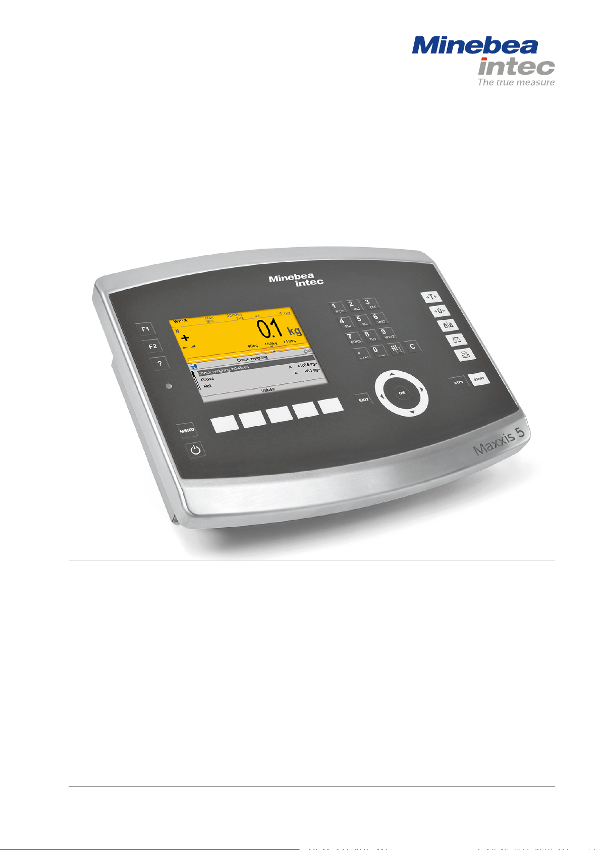
Process Controller Maxxis 5 PR 5900
Translation of original operating instructions 9499 050 59900 Edition 6.1.1 02/26/2018
Release 2.26.xx-Exx
Minebea Intec GmbH, Meiendorfer Str. 205 A, 22145 Hamburg, Germany
Phone: +49.40.67960.303 Fax: +49.40.67960.383

Foreword
Must be followed!
Any information in this document is subject to change without notice and does not represent a commitment on
the part of Minebea Intec unless legally prescribed. This product should be operated/installed only by trained
and qualied personnel. In correspondence concerning this product, the type, name, and release number/serial
number as well as all license numbers relating to the product have to be cited.
Note
The product is partially protected by copyright. It may not be changed or copied, and it may not be used without
purchasing or written permission from the copyright owner (Minebea Intec). Its use constitutes acceptance by
you of the above-mentioned provisions.

Process Controller Maxxis 5 PR 5900 Table of contents
Table of contents
1 Introduction......................................................................................................................................... 6
1.1 Read the manual.........................................................................................................................................................6
1.2 This is what operating instructions look like..........................................................................................................6
1.3 This is what lists look like........................................................................................................................................... 6
1.4 This is what menu items and softkeys look like..................................................................................................... 6
1.5 This is what the safety instructions look like..........................................................................................................6
1.6 Hotline.......................................................................................................................................................................... 7
2 Commissioning..................................................................................................................................... 8
2.1 Display and control panel.......................................................................................................................................... 8
2.1.1 Overview............................................................................................................................................................8
2.1.2 Display elements..............................................................................................................................................8
2.1.3 Operating elements........................................................................................................................................ 11
2.1.4 Display and operation using VNC client..................................................................................................... 18
2.2 Data security and data storage .............................................................................................................................. 18
2.2.1 Power failure................................................................................................................................................... 18
2.2.2 Warm start....................................................................................................................................................... 18
2.2.3 Cold start ......................................................................................................................................................... 18
2.3 Switching on the device........................................................................................................................................... 19
2.4 Switching o the device..........................................................................................................................................20
2.5 Device warm-up time...............................................................................................................................................20
2.6 Operating via front-panel keys/PC keyboard......................................................................................................20
2.7 Overwrite protection................................................................................................................................................20
2.7.1 CAL switch.......................................................................................................................................................20
2.7.2 Software..........................................................................................................................................................22
2.8 Switching on blackbox device ................................................................................................................................24
2.8.1 Connecting to remote terminal PR 5900/6x, ../7x...................................................................................24
2.8.2 Network settings............................................................................................................................................24
2.8.3 Connecting to notebook/PC ........................................................................................................................25
2.9 Operating via a notebook/PC.................................................................................................................................26
2.9.1 Finding and connecting the device automatically in the network .........................................................26
2.9.2 Finding and connecting a device with a notebook/PC ............................................................................26
2.9.3 Searching the device in the network with "IndicatorBrowser" ...............................................................27
2.9.4 Resetting the network address....................................................................................................................29
2.9.5 Operation using VNC.....................................................................................................................................29
2.9.6 Operation via a web browser .......................................................................................................................30
3 Operation and control ........................................................................................................................ 32
3.1 User login/logout .....................................................................................................................................................32
3.1.1 User login ........................................................................................................................................................32
3.1.2 User Logout....................................................................................................................................................33
EN-1 Minebea Intec

Process Controller Maxxis 5 PR 5900 Table of contents
3.2 User management.................................................................................................................................................... 33
3.3 Selecting the operating language..........................................................................................................................34
3.4 System menu.............................................................................................................................................................34
3.5 Help functions...........................................................................................................................................................36
3.6 Alibi memory.............................................................................................................................................................36
3.7 Showing the calibration data.................................................................................................................................. 37
3.8 Increased resolution (10-fold) of the weight value .............................................................................................37
3.9 Functions via the website........................................................................................................................................ 37
3.9.1 Display weighing points in a table ..............................................................................................................39
3.9.2 Browse database........................................................................................................................................... 40
3.9.3 Browsing the Alibi memory......................................................................................................................... 40
3.9.4 Displaying manuals ....................................................................................................................................... 41
3.9.5 Browse the event log..................................................................................................................................... 41
3.9.6 Browse log les ..............................................................................................................................................42
3.9.7 Displaying a log of the last system error....................................................................................................42
3.9.8 Screenshot ......................................................................................................................................................43
3.9.9 Export database.............................................................................................................................................43
3.9.10 Export Alibi memory......................................................................................................................................44
3.9.11 Export service report.....................................................................................................................................44
3.9.12 Backup and restore setup data....................................................................................................................45
3.9.13 Loading language les..................................................................................................................................47
3.10 BIOS BOOT menu .....................................................................................................................................................47
3.10.1 Open BIOS BOOT menu................................................................................................................................48
3.10.2 BIOS BOOT menu in blackbox device.........................................................................................................54
3.10.3 System messages in blackbox device.........................................................................................................54
4 System setup......................................................................................................................................56
4.1 Connected devices ...................................................................................................................................................57
4.1.1 Remote display............................................................................................................................................... 57
4.1.2 ModBus-RTU master.....................................................................................................................................59
4.1.3 PC via EW-Com............................................................................................................................................... 61
4.1.4 Printer..............................................................................................................................................................63
4.1.5 Remote terminal .............................................................................................................................................71
4.1.6 Barcode scanner (with Ex approval).............................................................................................................71
4.2 Date & time ................................................................................................................................................................73
4.3 Operating parameters .............................................................................................................................................75
4.4 Network parameters ............................................................................................................................................... 80
4.5 Network share connections ....................................................................................................................................83
4.5.1 Add...................................................................................................................................................................84
4.5.2 Change.............................................................................................................................................................86
4.5.3 Remove............................................................................................................................................................87
4.6 Fieldbus parameters ................................................................................................................................................88
4.6.1 Fieldbus settings for the SPS .......................................................................................................................89
Minebea Intec EN-2

Process Controller Maxxis 5 PR 5900 Table of contents
4.7 Weighing points........................................................................................................................................................90
4.7.1 Internal weighing point.................................................................................................................................92
4.7.2 Liquid counter .............................................................................................................................................. 123
4.7.3 User scale ...................................................................................................................................................... 126
4.7.4 A+B (scale)..................................................................................................................................................... 129
4.7.5 xBPI scale ...................................................................................................................................................... 132
4.7.6 SBI scale......................................................................................................................................................... 157
4.7.7 Pendeo Truck.................................................................................................................................................161
4.7.8 Pendeo Process............................................................................................................................................ 187
4.7.9 PR-Net weighing point ............................................................................................................................... 213
4.7.10 Mettler-Scale ................................................................................................................................................216
4.7.11 SMA scale ...................................................................................................................................................... 221
4.8 Display settings.......................................................................................................................................................225
4.9 License settings ......................................................................................................................................................226
4.9.1 Application license.......................................................................................................................................227
4.9.2 Demo mode ..................................................................................................................................................227
4.9.3 Default (restoring factory settings)...........................................................................................................229
4.10 User management..................................................................................................................................................229
4.10.1 Create user .................................................................................................................................................... 231
4.10.2 Copy user.......................................................................................................................................................234
4.10.3 Change user settings...................................................................................................................................235
4.10.4 Remove user.................................................................................................................................................236
4.10.5 Deactivate user management....................................................................................................................238
4.10.6 Error logging in ............................................................................................................................................238
4.11 Alibi memory.......................................................................................................................................................... 240
4.11.1 Tidy up records............................................................................................................................................. 241
4.11.2 Delete.............................................................................................................................................................242
5 System information..........................................................................................................................244
5.1 Show version .......................................................................................................................................................... 245
5.2 Show status ............................................................................................................................................................ 246
5.3 Show alarm information........................................................................................................................................247
5.4 Show HW options .................................................................................................................................................. 248
5.5 Show ModBus-TCP I/O module .......................................................................................................................... 249
5.6 Browsing the Alibi memory................................................................................................................................... 251
5.6.1 Search for specic date in Alibi memory.................................................................................................. 251
5.6.2 Search for a given sequence number ...................................................................................................... 254
5.6.3 Status Alibi memory ....................................................................................................................................255
5.7 Show calibration check number...........................................................................................................................256
5.8 Show Pendeo data..................................................................................................................................................257
5.9 Show event log....................................................................................................................................................... 260
5.10 Print conguration settings.................................................................................................................................. 261
EN-3 Minebea Intec

Process Controller Maxxis 5 PR 5900 Table of contents
6 System maintenance ........................................................................................................................ 263
6.1 Backup..................................................................................................................................................................... 264
6.1.1 SD card...........................................................................................................................................................265
6.1.2 USB stick........................................................................................................................................................267
6.1.3 Shared directory.......................................................................................................................................... 269
6.2 Restore..................................................................................................................................................................... 271
6.2.1 SD card........................................................................................................................................................... 273
6.2.2 USB stick........................................................................................................................................................275
6.2.3 Shared directory...........................................................................................................................................278
6.3 Export....................................................................................................................................................................... 281
6.3.1 USB stick........................................................................................................................................................282
6.3.2 Shared directory.......................................................................................................................................... 284
6.4 Import...................................................................................................................................................................... 286
6.4.1 USB stick....................................................................................................................................................... 288
6.4.2 Shared directory........................................................................................................................................... 291
6.5 Alibi memory maintenance .................................................................................................................................. 294
6.5.1 Export selection of records.........................................................................................................................295
6.5.2 Export + tidy up selection of records....................................................................................................... 298
6.5.3 Print selection of records........................................................................................................................... 302
6.5.4 Print + tidy up selection of records.......................................................................................................... 305
6.6 SD card maintenance ............................................................................................................................................ 308
6.6.1 Format SD card............................................................................................................................................ 309
6.6.2 Cleanup backups.......................................................................................................................................... 310
6.7 Create service report...............................................................................................................................................311
6.8 Shutdown & power o........................................................................................................................................... 313
6.8.1 Shutdown & Power o (without SD card)................................................................................................. 314
6.9 Update software ..................................................................................................................................................... 314
6.9.1 Update (soft key).......................................................................................................................................... 315
6.9.2 Update software............................................................................................................................................317
6.9.3 Update software with FlashIt .....................................................................................................................326
6.9.4 Update software for remote terminal.......................................................................................................329
6.9.5 Remove application.....................................................................................................................................330
6.9.6 Restore software from SD card.................................................................................................................. 331
6.10 Factory reset............................................................................................................................................................ 331
6.11 Test hardware..........................................................................................................................................................332
6.11.1 Display test....................................................................................................................................................333
6.11.2 Keyboard test ...............................................................................................................................................334
6.11.3 I/O cards test ................................................................................................................................................335
7 ModBus protocol ............................................................................................................................. 345
7.1 General description ................................................................................................................................................345
8 Fieldbus interface ............................................................................................................................ 346
Minebea Intec EN-4

Process Controller Maxxis 5 PR 5900 Table of contents
8.1 General notes ......................................................................................................................................................... 346
8.2 Scale protocol......................................................................................................................................................... 346
8.2.1 Data exchange range ................................................................................................................................. 346
8.2.2 Reading and writing data with function numbers................................................................................. 349
8.2.3 Reading and writing bits directly ............................................................................................................. 350
8.2.4 Waiting for the result of the action........................................................................................................... 351
8.2.5 Function numbers........................................................................................................................................ 351
8.2.6 Example: reading the gross weight...........................................................................................................356
8.2.7 Special note for DeviceNet and EtherNet IP............................................................................................357
8.3 SPM protocol ...........................................................................................................................................................357
8.3.1 Data exchange range ..................................................................................................................................357
8.3.2 Function numbers....................................................................................................................................... 358
8.3.3 Error code......................................................................................................................................................359
8.3.4 Data exchange modes................................................................................................................................ 360
9 Error messages ................................................................................................................................ 363
9.1 Error messages measuring circuit........................................................................................................................363
9.2 Error messages for xBPI scales............................................................................................................................ 364
9.3 Error messages for Pendeo load cells .................................................................................................................365
9.4 Error messages at PR-Net weighing point .........................................................................................................366
9.5 Error messages at "Mettler-Scale" weighing point ...........................................................................................366
9.6 Warnings when assigning a weighing point.......................................................................................................366
9.7 Error messages during calibration.......................................................................................................................367
9.7.1 Determine MAX (maximum capacity) .......................................................................................................367
9.7.2 Determining the scale interval.................................................................................................................. 368
9.7.3 Determining the dead load ....................................................................................................................... 368
9.7.4 Calibrating with weight...............................................................................................................................369
9.8 Error status in "LAST_ERROR"..............................................................................................................................370
10 Printouts ...........................................................................................................................................371
10.1 Conguration printout............................................................................................................................................371
10.2 Test printout............................................................................................................................................................375
10.3 Alibi printout ...........................................................................................................................................................376
EN-5 Minebea Intec

Process Controller Maxxis 5 PR 5900 1 Introduction
1 Introduction
1.1 Read the manual
- Please read this manual carefully and completely before using the product.
- This manual is part of the product. Keep it in a safe and easily accessible location.
-
1.2 This is what operating instructions look like
1. - n. are placed before steps that must be done in sequence.
is placed before a step.
describes the result of a step.
1.3 This is what lists look like
- indicates an item in a list.
1.4 This is what menu items and softkeys look like
[ ] frame menu items and softkeys.
Example:
[Start]- [Applications]- [Excel]
1.5 This is what the safety instructions look like
Signal words indicate the severity of the danger involved when measures for preventing
hazards are not followed.
DANGER
Warning of personal injury
DANGER indicates death or severe, irreversible personal injury which will occur if the
corresponding safety measures are not observed.
Take the corresponding safety precautions.
WARNING
Warning of hazardous area and/or personal injury
WARNING indicates that death or severe, irreversible injury may occur if appropriate
safety measures are not observed.
Take the corresponding safety precautions.
CAUTION
Warning of personal injury.
CAUTION indicates that minor, reversible injury may occur if appropriate safety
measures are not observed.
Take the corresponding safety precautions.
Minebea Intec EN-6

1 Introduction Process Controller Maxxis 5 PR 5900
NOTICE
Warning of damage to property and/or the environment.
NOTICE indicates that damage to property and/or the environment may occur if
appropriate safety measures are not observed.
Take the corresponding safety precautions.
Note:
User tips, useful information, and notes.
1.6 Hotline
Phone: +49.40.67960.444
Fax: +49.40.67960.474
eMail: help@minebea-intec.com
EN-7 Minebea Intec
.
Process Controller Maxxis 5 PR 5900 2 Commissioning
2 Commissioning
2.1 Display and control panel
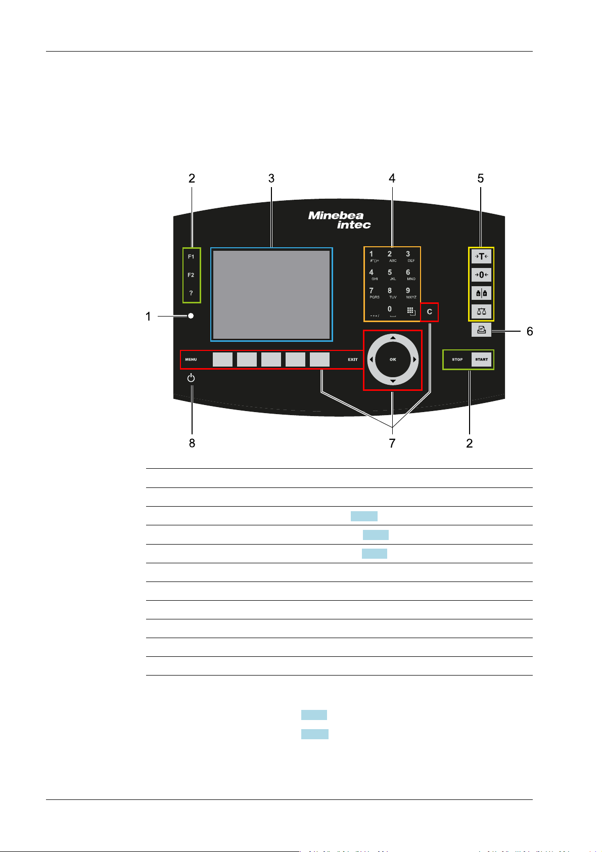
2.1.1 Overview
No. Name
1 LED status display, see Chapter 2.1.2.2
3 5.7" TFT color display, see Chapter 2.1.2.1
2 Function keys
4 Alphanumeric keypad
5 Indicator keys
6 Application keys
7 Navigation/menu keys, incl. soft keys
8 On/o button
2.1.2 Display elements
- TFT screen display, see Chapter 2.1.2.1
- LED status display, see Chapter 2.1.2.2
Display elements
Operating elements, see Chapter 2.1.3.1
Minebea Intec EN-8
WP-A
Max 12200g d= 0.1g
Min 5g e= 1g
9
041
g
N
+
5g 12200g
Weighing point A @admin
Net=Gross
Net
Tare
<1115.[9] g>
<140.[9] g>
975.0 g
A
A
A
Set tare
7654
3
2
1
2 Commissioning Process Controller Maxxis 5 PR 5900
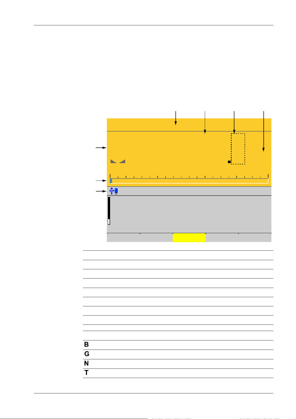
2.1.2.1 TFT user interface display
The TFT color graphics display can show weight values of up to 7 digits with decimal point
and plus or minus sign. The available mass units are t, kg, g, mg, lb, or oz.
The lb and oz units are not permitted for use in legal metrology in the EU and EEC.
Below the weight display, the currently displayed weight is shown in a bar graph that
indicates the percentage of the maximum capacity (Max). 0 is on the left, and 100% on the
right.
No. Description
1 Info line
2 Bar graph
3 Weight type/plus or minus sign/standstill
4 Status display
5 Weight value
6 Border around decimal place
7 Symbols/mass unit
Weight type/plus or minus sign Description
EN-9 Minebea Intec
Gross weight
Gross weight in NTEP or NSC mode
Net weight (Net = gross - tare)
Tare weight
Process Controller Maxxis 5 PR 5900 2 Commissioning
Weight type/plus or minus sign Description
Preset tare, not tared
No display - Test value
- Gross, not tared
Additional weight display, application-dependent
Additional weight display, application-dependent
Additional weight display, application-dependent
Positive value
Negative value
Standstill/zero/batching/monitoring
Symbols/mass unit Description
R1 Range 1
R2 Range 2
R3 Range 3
Description
Weight value standstill
The gross weight value is within ±¼ d of zero
Batching mode: ashes when batching is "stopped";
rapid ashing indicates "error status"
Pendeo load cells: Plausibility monitoring; the average deviation of the individual load cells is calculated
Pendeo load cells: Temperature monitoring; 1–n
load cells above or below permissible temperature
Value not permissible in legal metrology (e.g., 10x
resolution, deactivated load cell)
WP A Weighing point A
WP B Weighing point B
WP C Weighing point C
WP D Weighing point D
Max Maximum capacity (weighing range)
Min Minimum weight
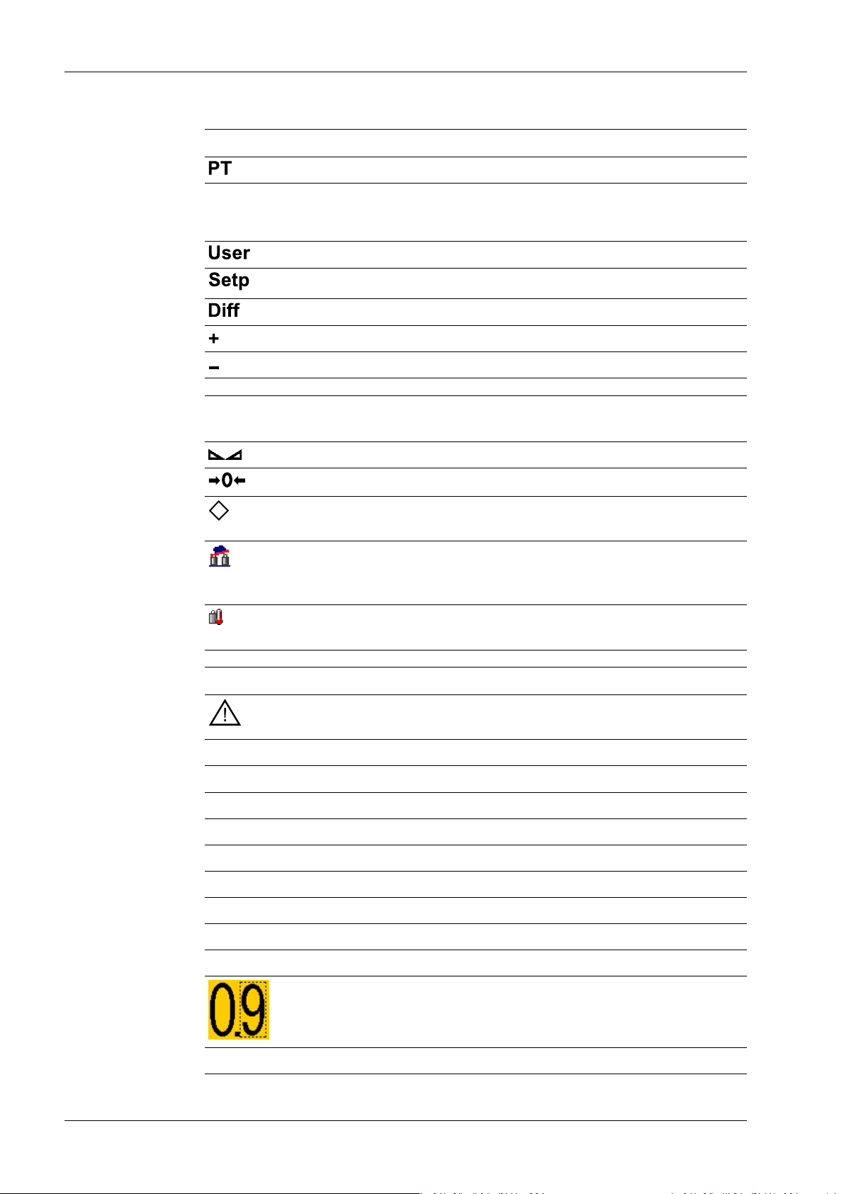
Only if W&M is selected: Border around inadmissible
decimal place.
t, kg, g, mg, lb, oz These mass units are available.
Minebea Intec EN-10

2 Commissioning Process Controller Maxxis 5 PR 5900
Status icons in the info line
Icon Description
Remote control via VNC (Virtual Network Computing) is active.
- The clock battery is empty.
- The standby battery is empty.
The standby battery is too hot and is not charging.
If this does not go away, the ambient temperature
must be checked, see PR 5900 installation manual
under [Technical data] - [Environmental inuences]
- [Ambient conditions].
- An unsupported USB device is connected.
- The maximum current of i
= 200 mA has be-
max
en exceeded.
Check newly connected devices.
2.1.2.2 LED status display
Operating status Color LED status Description
Normal operation O
System ready (standby) Red Continuous illu-
Power interruption
<5 seconds
Power interruption
>5 seconds
USB stick was recognized and is operational.
Stick is in use and may not be removed.
Conict in the network settings of the IP address.
Interface (C1/CX1) was detected. However, there is
no connection to the operator terminal.
The display (screen) is switched
mination
o.
Red Slow ashing After 5 seconds, the device re-
turns to normal operation.
Red Fast ashing The device is running a data ba-
ckup. Once power is restored, the
device returns to normal operation (LED o).
After the data backup,
O The device switches o.
there is still a power interruption.
Power is restored O The device initiates a warm start,
see Chapter 2.2.2.
2.1.3 Operating elements
- Operation using the front-panel keys, see Chapter 2.1.3.1
EN-11 Minebea Intec
Process Controller Maxxis 5 PR 5900 2 Commissioning
- Operation using the soft keys, see Chapter 2.1.3.2
- Operation using the navigation keys, see Chapter 2.1.3.3
- Operation using the PC keys, see Chapter 2.1.3.4
- Operation using the VNC program, see Chapter 2.1.4
2.1.3.1 Operation using the front-panel keys
The following table shows the basic meanings of the symbols on the front-panel keys.
Depending on the applications, the keys may also have other meanings.
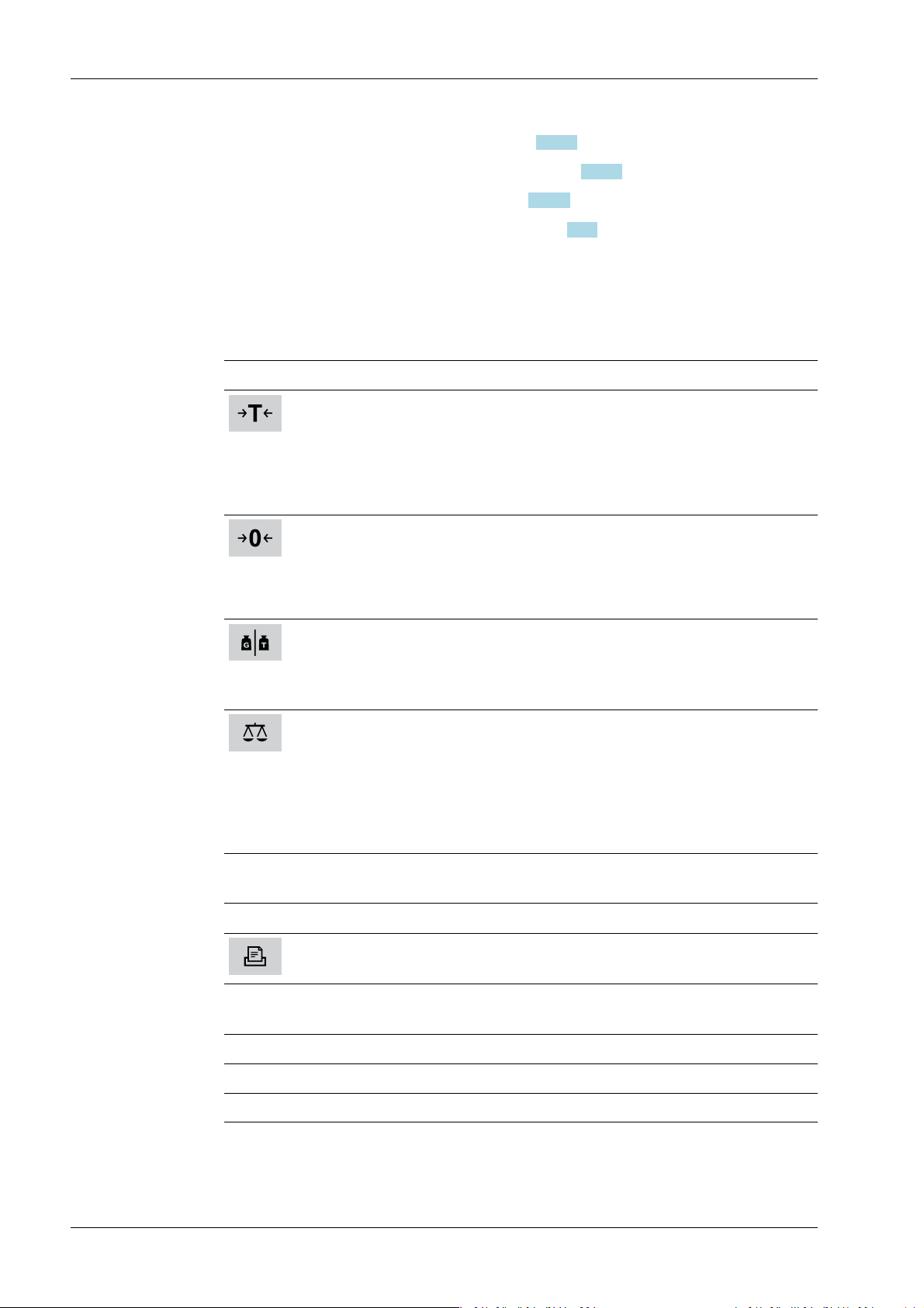
Indicator keys
Key Description
Set tare
The current gross weight is stored in the tare memory, provided that
- the weight value is stable.
- the device is not in error status.
(Function is dependent on conguration)
Sets gross weight to zero, provided that
- the weight value is stable.
- weight is within zero setting range.
(Function is dependent on conguration)
Display gross/tare weight
Pressing the key switches to the next weight (only with tared scale).
During calibration, pressing this key displays the weight for 5 seconds with
10x resolution.
Switching of display between the weighing points:
- WP‑A
- WP‑B
- WP‑C
- WP‑D
Application keys
Key Description
Starts an application-specic printout.
Navigation keys
Key Description
▲ Scroll up in the menu.
▼ Scroll down in the menu.
Minebea Intec EN-12
2 Commissioning Process Controller Maxxis 5 PR 5900
Key Description
◀ - Cursor to the left
- Selection
- Exit menu window.
▶ - Cursor to the right
- Selection
- Conrm input/selection.
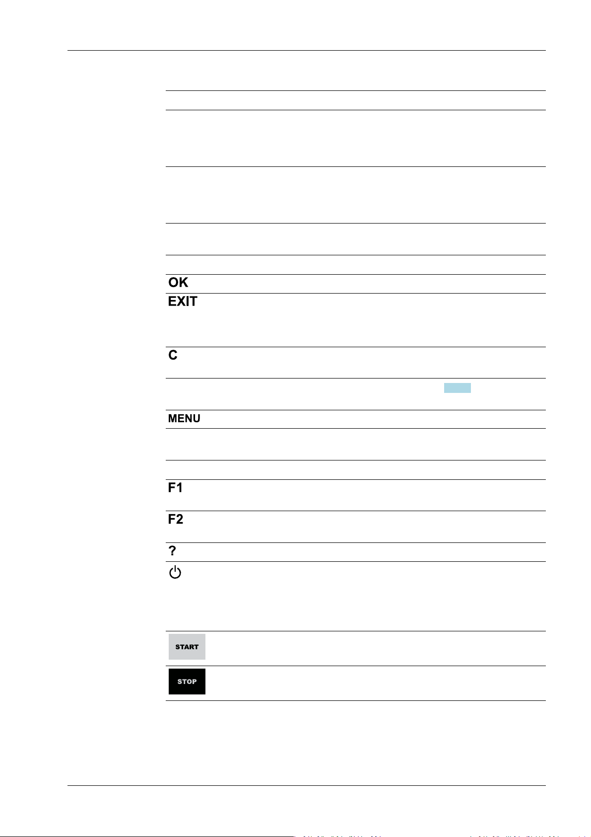
Menu keys
Key Description
Conrm input/selection.
- Cancel entry/selection (after a conrmation prompt) without saving
the change.
- Exit parameters/menu window.
Pressing the delete key deletes individual characters (within an entry) or
whole strings of characters.
Soft key 1 to5Select appropriate menu function, see also Chapter 2.1.3.2.
Switch to the operating menu.
Function keys
Key Description
Assigned to a dened function (see system menu [System setup] - [Operating parameters]).
Assigned to a dened function (see system menu [System setup] - [Operating parameters]).
Displays the relevant help window.
- Turns o the display.
- Ignores all key presses.
- LED is red.
Pressing again will switch the display on again.
Starts an application-specic function.
Stops an application-specic function.
EN-13 Minebea Intec
.
Process Controller Maxxis 5 PR 5900 2 Commissioning
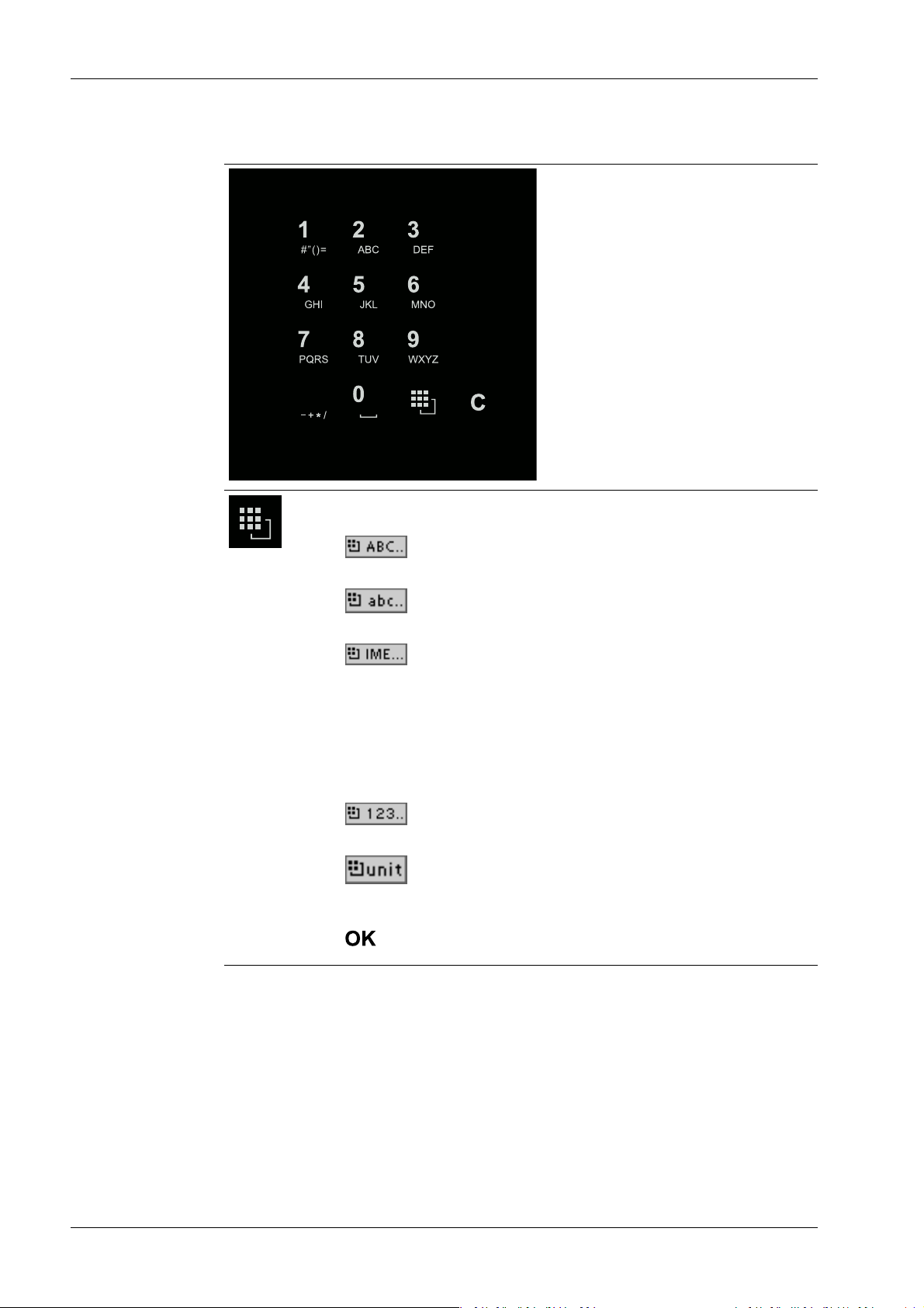
Alphanumeric keypad
Toggle key
Pressing switches between the following functions:
-
Uppercase letters
-
Lowercase letters
-
Pinyin
When Chinese has been selected or set under [Operating parameters]
- [Input method].
- Hepburn
When Japanese has been selected or set under [Operating parameters] - [Input method].
-
Numbers
-
Units
Select the unit using the cursor keys ▲/▼ and conrm using the key
.
Minebea Intec EN-14
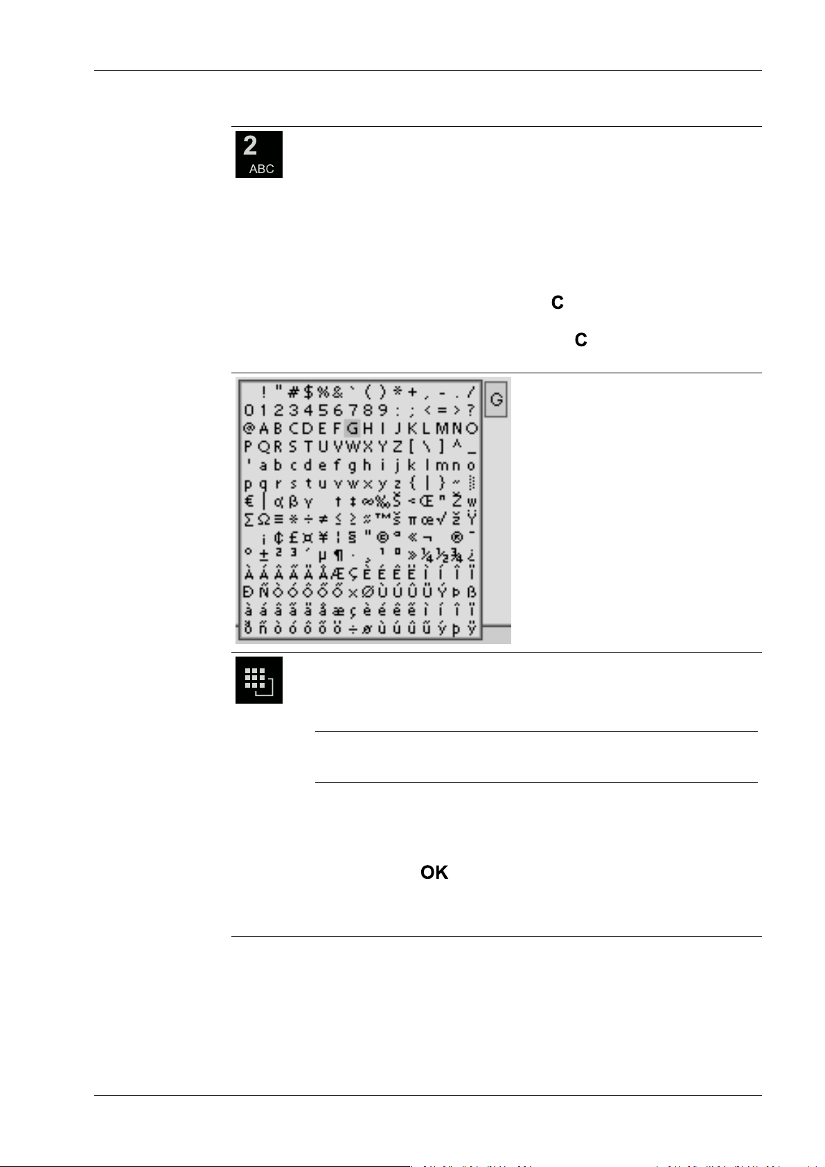
2 Commissioning Process Controller Maxxis 5 PR 5900
Input without the character table
Pressing once displays the corresponding rst character, e.g., "A", at the
cursor position. After pressing twice, "B" is displayed at the cursor position
and after pressing three times, "C" is displayed.
Press the cursor keys ▼/▲ to nish entering a character or wait approx.
2 seconds.
If only numeric values are required for input, letters are not enabled.
Press the cursor key ◀ within an entry to return to the previous character.
Press the cursor key ▶ within an entry to select the next character.
Within an entry, pressing the delete key deletes the character to the left
of the cursor.
Outside of an input, pressing the delete key deletes the whole string of
characters.
Input with the character table
Double-clicking on the key displays the character table.
Only characters authorized for this input are displayed.
Note:
The switching function is turned o.
Procedure:
- Highlight the desired character with the cursor.
- The selected character is shown magnied in the eld at the top right.
- Press the key to enter the character in the input eld.
- Another double-click on the toggle key and other characters can be in-
put as described previously.
EN-15 Minebea Intec
WP-A
Max 3000g d= 0.1g
+
A
B
C
Enter user name and password
User name
Password
********
WP-A
Max 3000g d= 0.1g
+
Enter user name and password
User name
Password
********
ABC..
Default Save
Process Controller Maxxis 5 PR 5900 2 Commissioning
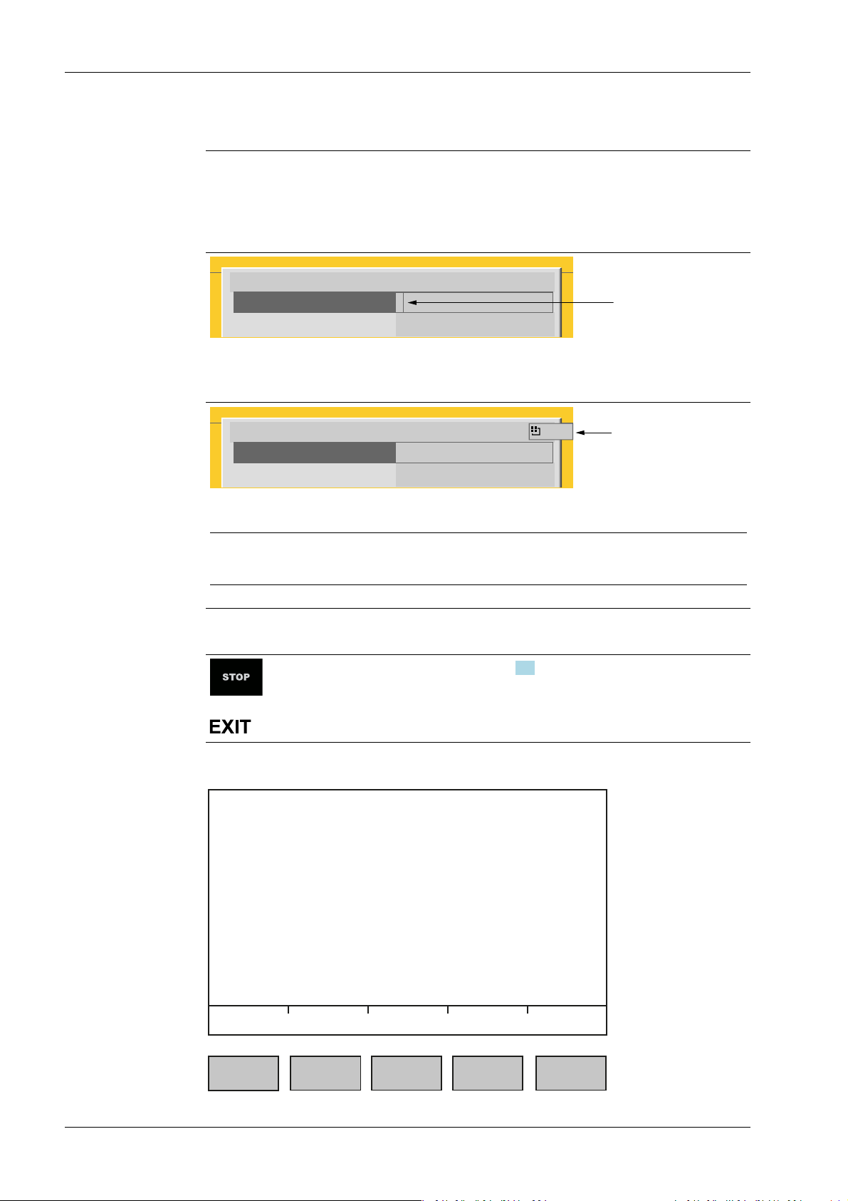
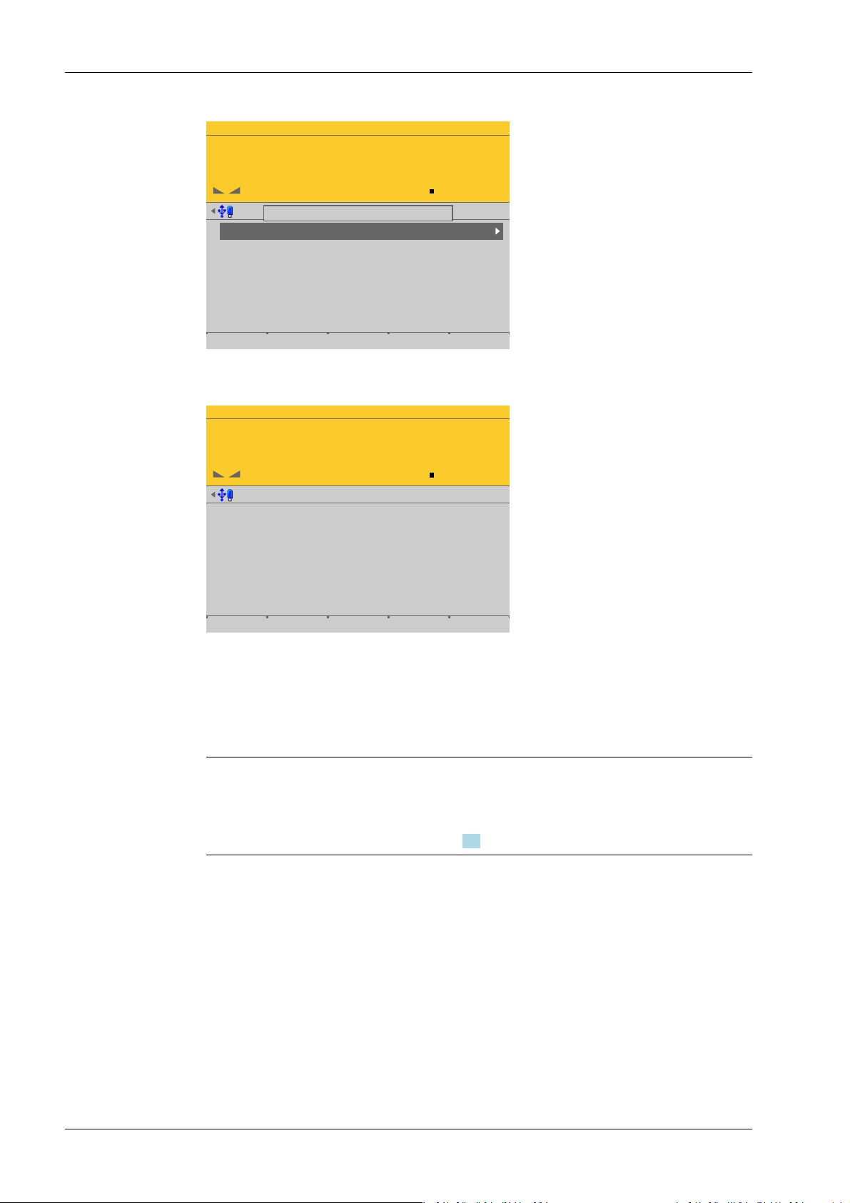
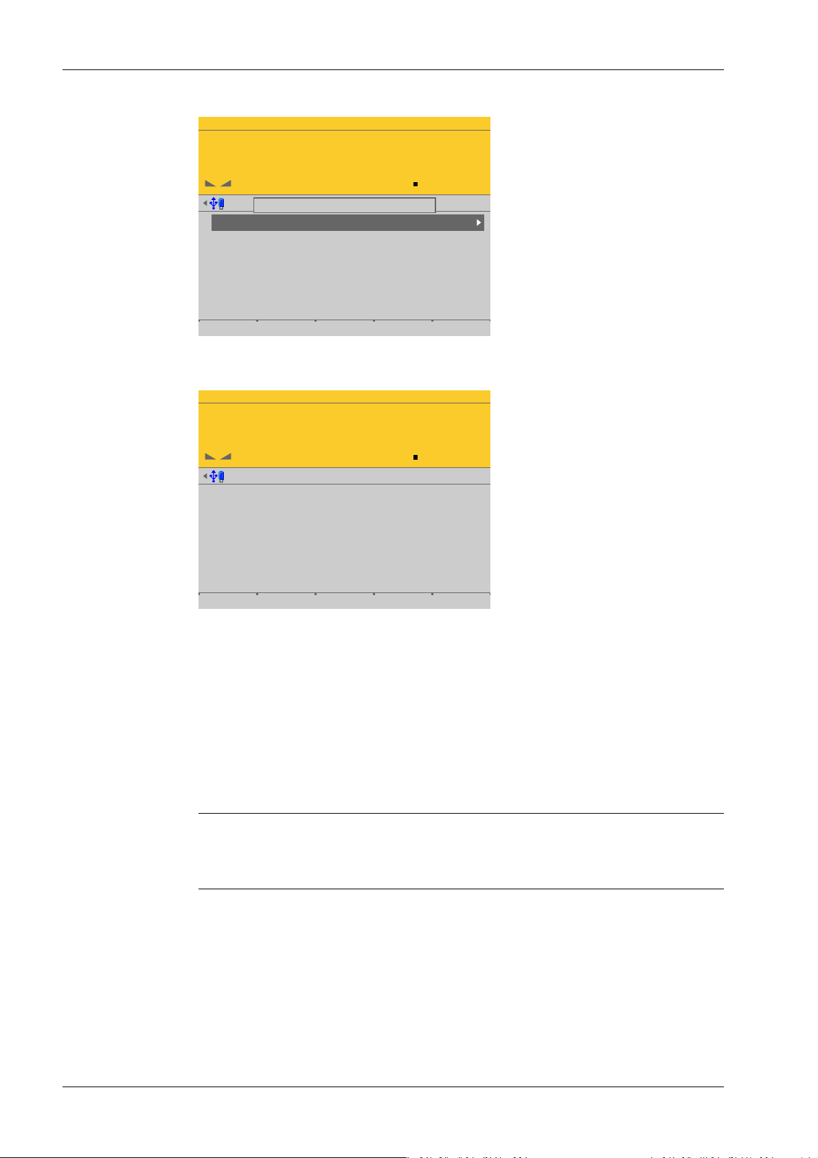
Input eld
In principle:
If alphanumeric characters are already present in the input eld of the selected line, they
will be completely overwritten after immediate entry.
If alphanumeric characters are already present in the input eld of the selected line, you
can press the cursor key ▶ to select the characters to be overwritten and overwrite them.
In front of the input eld it is indicated whether numeric and/or alphabetic characters
can be entered (see arrow).
Switch to the input eld using the cursor key ▶.
The respective options are displayed (see arrow).
Note:
The character table is turned o.
Keyboard shortcuts
+
2.1.3.2 Operation using softkeys
Trigger a cold start, see also Chapter 4.3.
Minebea Intec EN-16
2 Commissioning Process Controller Maxxis 5 PR 5900
The functions of the ve softkeys below the graphic display are indicated in the
bottommost text line of the display. Softkey functions shown in gray cannot be selected
at the active menu level or with the current access privileges.
In the descriptions of operating sequences which entail the use of softkeys, the softkey
function to be selected is shown in square brackets; the softkey symbol is not displayed;
example: [Save].
2.1.3.3 Navigation key operation Menu
The cursor keys, the and keys are used to navigate through the menus.
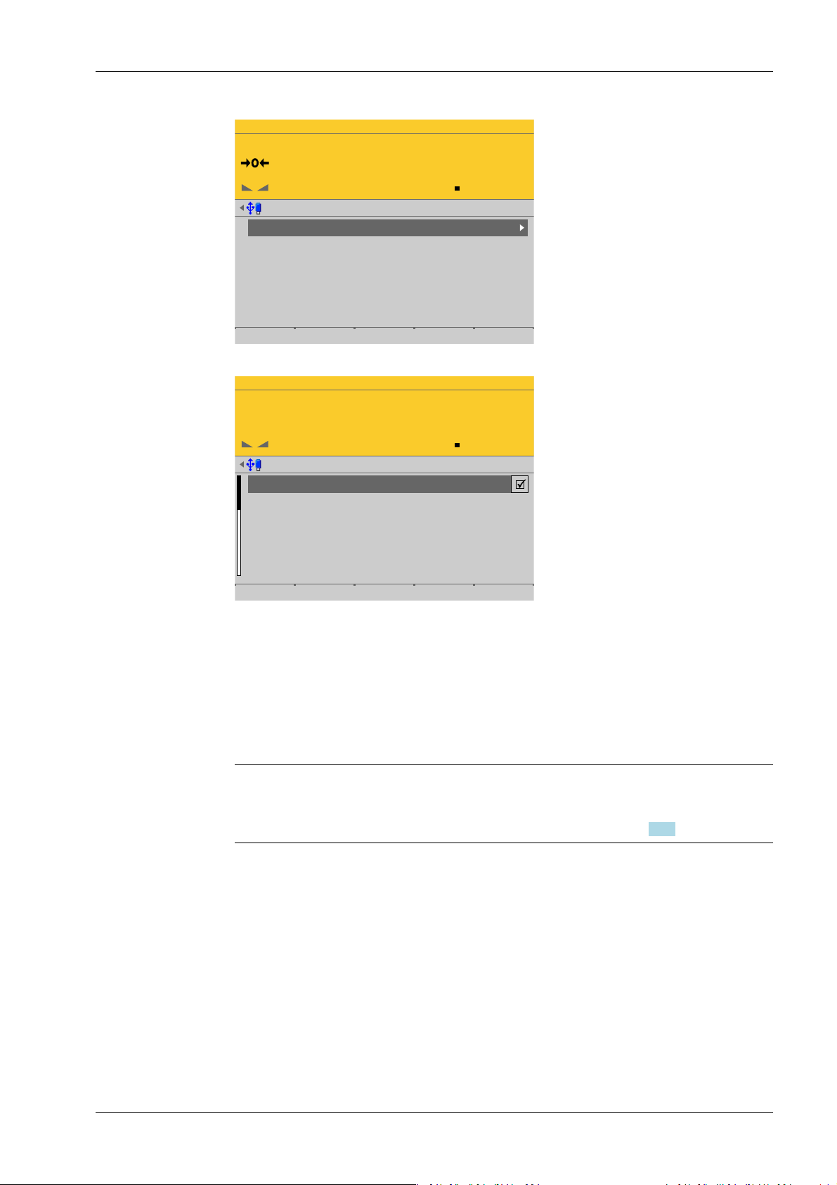
Parameters
Use the ▼/▲ cursor keys to select the individual parameters.
Use the key to conrm the selection.
The required values | texts are entered via the alphanumeric keys.
The key is used to check the ☑ box.
If the list of parameters is long, a vertical bar graph on the left (black and gray) shows
which part of the list is displayed.
An existing selection list is indicated by an arrow ▶ following it.
The parameter is selected using the key.
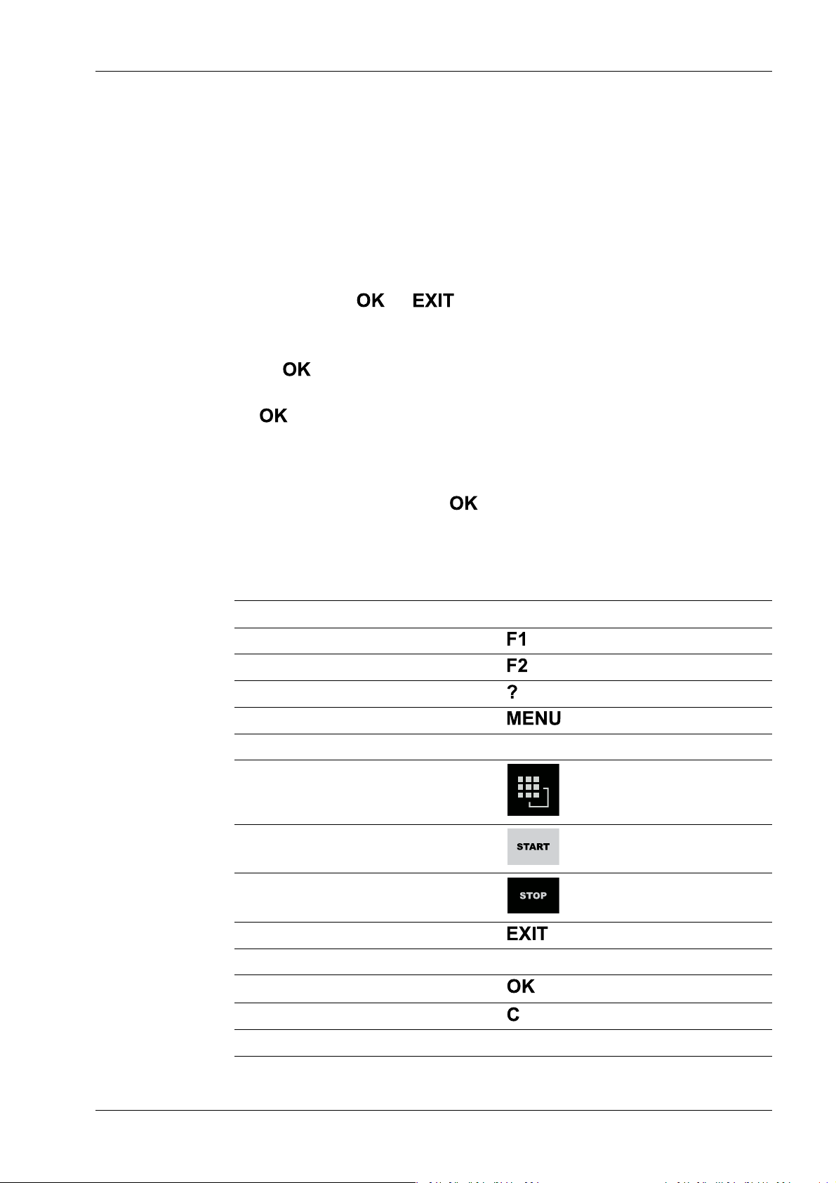
2.1.3.4 Operation via PC keys
The device can also be operated using a PC keyboard. The corresponding key assignment
is shown in the table below:
PC keyboard Front keypad
F1
F2
F3
F4
F5…F9 Softkey 1…5
F10
F11
F12
ESC
Cursor keys: ↑, ↓, ←, → ▲, ▼, ◀, ▶
Enter key: ↵
Backspace key: ←
Numeric keypad Alphanumeric keypad
EN-17 Minebea Intec

Process Controller Maxxis 5 PR 5900 2 Commissioning
2.1.4 Display and operation using VNC client
The display and operating elements are described in the following chapters:
- Overview of front of device, see Chapter 2.1.1.
- User interface of TFT screen, see Chapter 2.1.2.1.
- Operation using the front-panel keys, see Chapter 2.1.3.1.
Setting up the VNC client, see Chapter 2.9.5.
2.2 Data security and data storage
The calibration data and parameters of the internal weighing electronics system are saved
to the EAROM (Electrically Alterable ROM) on the weighing electronics board. Additional
write protection is provided for calibration data and parameters (see Chapter 2.7.2).
The event logger is saved to the SPI ash (Serial Peripheral Interface ash) memory.
The FlashPROM contains:
- BIOS
- Firmware
- Application Program
- Alibi memory
- XML conguration les (for user management, system setup, calibration and
The backups are stored on the SD card (Secure Digital card) (see also PR 5900 installation
manual under [Hardware construction]- [Main board]- [SD card slot] ).
2.2.1 Power failure
The entire content of the working memory is stored to a NAND ash memory and remains
there permanently when the power is interrupted or the device is disconnected from the
power.
The SD card and the USB stick are buered by a battery.
If a HUB (splitter) is inserted into the USB slot and turned o, the connection between the
USB stick and battery is broken.
2.2.2 Warm start
When power is restored, all data are reloaded from the NAND ash memory to the
working memory and the device is restored to the operating status before the
interruption. Filling programs are stopped/started depending on user settings.
2.2.3 Cold start
application data)
A cold start is performed if the device nds no saved data with which the last operating
state can be restored.
A cold start can have various causes:
- The battery has not been charged properly or is faulty, and it was not possible to save
all the data when the power was disconnected.
- The device was restarted using the STOP+EXIT keys, see Chapter 2.2.3.1.
- The reset key was pressed, see Chapter 2.2.3.2
Minebea Intec EN-18

2 Commissioning Process Controller Maxxis 5 PR 5900
- The STOP key was held down during startup and cold start was then selected, see
Chapter 3.10.
If available, the database from the last backup is restored after a cold start.
2.2.3.1 STOP+EXIT buttons Pressing STOP+EXIT simultaneously (see Chapter 4.3) initiates a cold start of the device:
- The settings are retained.
- The database is initialized.
- The device automatically searches for an existing database on the SD card and asks
whether this should be loaded.
- The application must be restarted.
Note:
If [Operating]- [System setup]- [Operating parameters]- [Cold start with STOP+EXIT][disabled] is selected in the menu, the device cannot be restarted with STOP+EXIT.
2.2.3.2 Reset key
Briey pressing (< 1 sec.) the reset key (see PR 5900 installation manual under [Process
controller]- [Housing]- [Housing dimensions]- [Control cabinet housing] ) initiates a cold
start of the device:
- The LED ashes once.
- The settings are retained.
- The database is initialized.
- The device automatically searches for an existing database on the SD card and asks
whether this should be loaded.
- The application must be restarted.
2.3 Switching on the device
Note:
The following steps must be followed when connecting the device to mains voltage for
the rst time:
- Set the date and time, see Chapter 4.2.
- Set up the network (only necessary if the device is to be used or congured in the
network), see Chapter 4.4.
The device can be set up as follows:
- Via keys on the front of the device, see Chapter 2.1.3.1.
- Via an external PC keyboard, see Chapter 2.1.3.4.
- Via a notebook/PC using the VNC software (included on the CD), see Chapter 2.9.5.
- Via a notebook/PC using an Internet browser, see Chapter 2.9.6.
EN-19 Minebea Intec
WP-A
Max 3000g d= 0.1g
00
+
g
0g 3000g
22.08.2012 15:20:46
Login
Process Controller Maxxis 5 PR 5900 2 Commissioning
When the device is powered up, the following appears:
Checking…
Booting…
Restore…
No signal Error message: if no load cells are connected, see also Chapter 9.1.
No values from
scale
Scale not ready Error message: if no load cells or no scale is connected (see also Chap-
The weight display appears.
The device is booting up.
Error message: if there is no communication with the xBPI scale (see
also Chapter 9.2).
Error message: unable to read weight values from the ADC (analog-digital converter); see also Chapter 9.1.
ter 9.1).
2.4 Switching o the device
Switching o the device, see Chapter 6.8.
2.5 Device warm-up time
A warm-up time of 30 minutes for the device is required before calibration is started.
2.6 Operating via front-panel keys/PC keyboard
The following options are possible:
- Via keys on the front of the device, see Chapter 2.1.3.1.
- Via an external PC keyboard (USB connection), see Chapter 2.1.3.4.
2.7 Overwrite protection
2.7.1 CAL switch
Overwrite protection can be activated using the CAL switch to prevent unauthorized
access to or overwriting of the calibration data/parameters.
The device can have up to 4 CAL switches. CAL switches 1 and 2 are located on the main
board and are accessible via two holes in the housing.
Minebea Intec EN-20
CAL 2
CAL 1
CAL 2
CAL 1
2 Commissioning Process Controller Maxxis 5 PR 5900
Depending on the model, CAL switches A and B may also be present. They are located on
the corresponding weighing electronics board (see PR 5900 installation manual). These
switches can only be accessed by removing the device housing.
The exact function of individual switches is listed in the table below.
Note:
In general, we recommend activating the overwrite protection features via the software
after calibration to prevent overwriting/data loss (see Chapter 2.7.2).
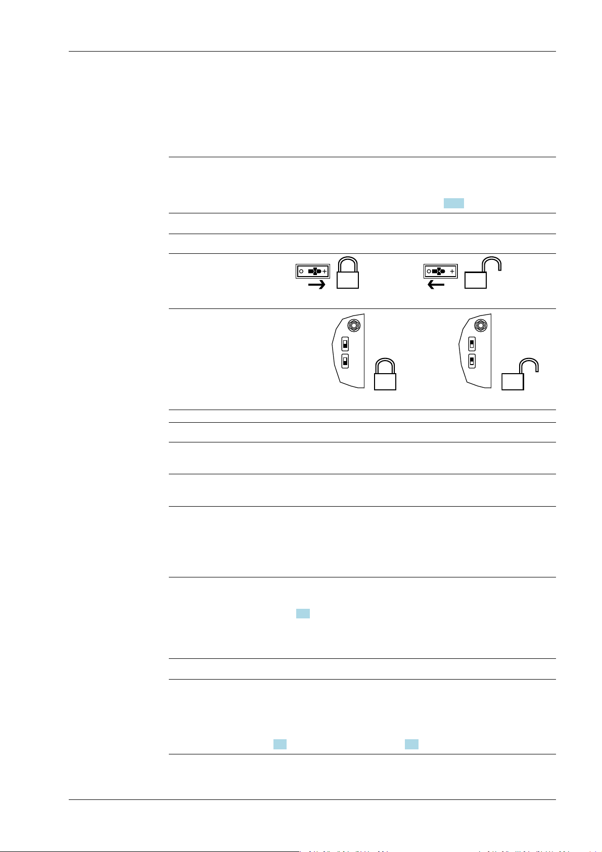
Write protection active Write protection inactive
CAL switches A and B
closed opened
CAL switches 1 and 2
closed
opened
CAL switch Meaning of "Write Protection Active"
A Prevents the calibration data/parameters of weighing electronics A
from being changed
B Prevents the calibration data/parameters of weighing electronics B
from being changed
1 The following changes are prevented:
- Allocation of weighing electronics to logical weighing points
- Calibration data and parameters of other weighing points
- Alibi settings
2 The following is prevented:
- Loading/ashing of rmware and BIOS to the device, see also
Chapter 6.9
- Changing of license settings
This CAL switch is sealed for use in legal metrology.
Note:
Changing means:
Changing by entering data into the input elds as well as changing via the functions
[Restore] (see Chapter 6.2) and [Import] (see Chapter 6.4).
EN-21 Minebea Intec
WP-A
Max 3000g d= 0.1g
00
+
g
Weighing points @admin
Weighing point A
Weighing point B
Weighing point C
Weighing point D
Internal weighing point
Internal weighing point
xBPI scale
Pendeo Process
Parameters Calib Units
CAL switch A is closed.
WP-A
Max 3000g d= 0.1g
00
+
g
Calibration (CAL switch is closed) @admin
Max
Scale interval
Dead load at
Max at
calibrated at
Sensitivity
3000.0 g
0.1 g
mV/V
mV/V
mV/V
µV/d
0.040800
1.177298
0.987557
0.470919
30000 d
1 d
103.966 g
3000.000 g
2516.5 g
98.11 cnt/d
Process Controller Maxxis 5 PR 5900 2 Commissioning
When a CAL switch is closed, a tool tip is displayed in the menu [Weighing points].
The data under the soft keys [Parameters], [Calibration], and [Units] is displayed only.
2.7.2 Software
Minebea Intec EN-22
Example of calibration data.
Overwrite protection can be activated via software to prevent unauthorized access to or
overwriting of the calibration data/parameters.
Note:
A unique check number is created every time a calibration or changed parameters are
saved. This can be viewed in the menu [Operating] - [System information] - [Show
calibration check numbers] (see Chapter 5.7) and may also be written on the W&M label.
Accessible via MENU – [Operating] - [System setup] - [Weighing points] - [Weighing
point x] - [Parameters] - [Settings locked].
WP-A
Max 3000g d= 0.1g
00
g
Weighing points @admin
Weighing point A
Weighing point B
Weighing point C
Weighing point D
Internal weighing point
Pendeo Truck
xBPI scale
User scale
Parameters Calib Units
WP-A
Max 3000g d= 0.1g
00
g
Weighing points @admin
Settings locked
W&M
Measurement time
Digital filter
Cutoff frequency
External load cell supply
none
160 ms
aperiodic
2.00 Hz
below or equal 8 V
Default Save
2 Commissioning Process Controller Maxxis 5 PR 5900
Each weighing point has a [Settings locked] parameter in the menu item [Parameters].
EN-23 Minebea Intec
If this parameter is set for the weighing point,
- the calibration data and parameters of the corresponding weighing point and the
weighing point allocation are only viewed as if the corresponding CAL switch were
closed.
- Only the [Settings locked] parameter can be changed.
- [Restoring]/[Importing] a weighing point is disabled.
Note:
If [Settings locked] and [W&M] have been selected for at least one weighing point, this
has the same eect as a closed CAL 1 and CAL 2 switch, see Chapter 2.7.1.
WP-A
Max 3000g d= 0.1g
00
+
g
Weighing points @admin
Weighing point A
Weighing point B
Weighing point C
Weighing point D
Internal weighing point
Pendeo Truck
xBPI scale
User scale
Parameters Calib Units
'Settings locked' is set
WP-A
Max 3000g d= 0.1g
00
+
g
Calibration (Settings locked) @admin
Max
Scale interval
Dead load at
Max at
calibrated at
Sensitivity
3000.0 g
0.1 g
mV/V
mV/V
mV/V
µV/d
0.040346
1.177703
0.987896
0.471081
30000 d
1 d
102.774 g
3000.000 g
2516.5 g
98.14 cnt/d
Process Controller Maxxis 5 PR 5900 2 Commissioning
If [Settings locked] is active, a tool tip appears in the menu [Weighing points].
The data under the soft keys [Parameters], [Calibration], and [Units] is displayed only.
2.8 Switching on blackbox device
2.8.1 Connecting to remote terminal PR 5900/6x, ../7x
2.8.2 Network settings
Minebea Intec EN-24
Example of calibration data.
The blackbox device can be operated with the PR 5900/6x, ../7x remote terminal.
There are no setting options for the connection to the remote terminal.
If the installation has been carried out correctly, the connection to the remote terminal is
automatically established.
Note:
For information on installation and switching on the remote terminal, see PR 5900/6x,
../7x instrument manual.
The device has the following factory settings:
- Device IP address (default): 192.168.1.2
- Subnet mask (default): 255.255.255.0
2 Commissioning Process Controller Maxxis 5 PR 5900
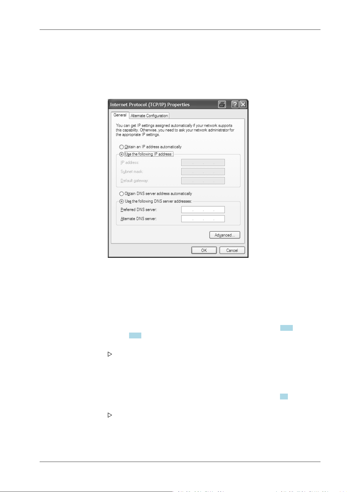
2.8.3 Connecting to notebook/PC
1. Do not establish a connection between the blackbox device and the network to begin
with!
2. Note down the notebook/PC network settings.
3. Disconnect the notebook/PC from the network.
4. In the notebook/PC, click the second line [Use the following IP address] (DHCP is now
deactivated).
5. Enter the xed IP address "192.168.1.2" and the subnet mask "255.255.255.0" and
save.
6. Directly connect the notebook/PC and blackbox device with a network cable (without
a splitter).
7. Open a web (Internet) browser (e.g. Microsoft Internet Explorer, Mozilla Firefox, etc.).
8. Enter the IP address of the blackbox device: 192.168.1.2, see Chapter 2.9.5 or
Chapter 2.9.6.
9. Conrm the entry.
The device name entered under [Host name] appears under the header in
brackets.
10. Note down the host name (here: "PR5900-27FF07").
11. In the menu [Operating]- [System setup]- [Network parameters] modify the network
address of the blackbox device to the required address or activate DHCP according to
the responsible system administrator's instructions; see also Chapter 4.4.
12. Save the settings.
The blackbox device sets itself to the new address.
This means that the connection to the notebook/PC is lost.
13. Disconnect the cable connection between the notebook/PC and blackbox device.
14. Connect the blackbox device to the network using a network cable.
EN-25 Minebea Intec

Process Controller Maxxis 5 PR 5900 2 Commissioning
15. Re-enter the network settings (as noted previously) on the notebook/PC.
The blackbox device will now be available on the network under the new address
and ready for operation.
Note:
Resetting the network settings (see also Chapter 2.8.2) by:
- Holding down the reset button for > 5 s, see Chapter 2.9.4.
- Selecting and conrming the menu [Operating]- [System setup]- [Network
parameters]- [Default] .
2.9 Operating via a notebook/PC
The following options are possible:
- Via VNC Viewer (on the enclosed CD-ROM), see Chapter 2.9.5.
- Via the internet browser, see Chapter 2.9.6.
Requirement:
The Java application must be supported by the web browser.
2.9.1 Finding and connecting the device automatically in the network
If the DHCP server is active in the network, the connected device (if activated in the menu
[Operating] - [Default conguration] - [Network parameters] - [use DHCP]) is
automatically assigned an IP address.
On the notebook/PC, the host names of the connected devices in the network are listed
under [Network].
Double-click the host name to open the device page in the web browser. The IP address is
displayed on the bottom right.
Note:
If the web browser supports the Java application, the device can be operated via[remote
conguration (VNC).]
If the web browser does not support the Java application, the menu items will be
inaccessible (grayed out).
2.9.2 Finding and connecting a device with a notebook/PC
If the device is connected to a notebook/PC via a point-to-point connection, an IP
address is negotiated via function "AutoIP". This can take up to 2 minutes!
NOTICE
When the IT/DHCP network cable is temporarily connected between the notebook/
PC and a device, the DHCP server is lost and the notebook/PC returns to the auto-IP
address within approx. two minutes!
Reason: The DHCP server/client relationship is checked cyclically at 23-minute
intervals.
Minebea Intec EN-26

2 Commissioning Process Controller Maxxis 5 PR 5900
1. On the notebook/PC, set the LAN local and Internet Protocol properties to "Obtain an
IP address automatically" depending on the operating system.
2. On the device, under MENU - [Default conguration] - [Network parameters] activate
the "Use DHCP" parameter (factory/default settings).
The DHCP devices nd each other because they fall into an "auto-IP address" in
the range 169.254.0.1169.254.255.254 with the associated auto-subnet mask
255.255.0.0 after a cyclical automatic DHCP server search run due to time
overow (23 minutes).
Example:
If the search time is exceeded (because there is "no server found"), the PR 5900 is
assigned to an IP address automatically (e.g. 169.254.0.123). The same applies to
the notebook or PC (e.g. 169.254.0.54).
These IP addresses are dierent on both sides:
- equal regarding the rst 2 octets of the IP address (e.g. network ID 169.254.)
- dierent in the last 2 octets of the IP address (e.g. host ID 0.123.)
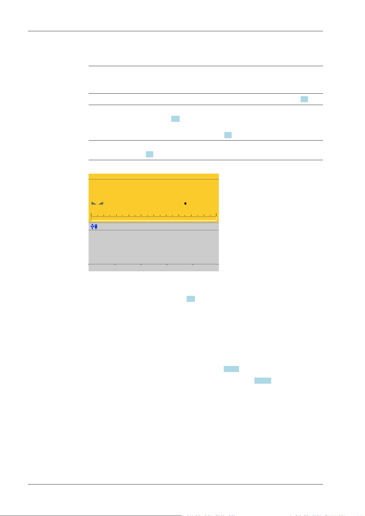
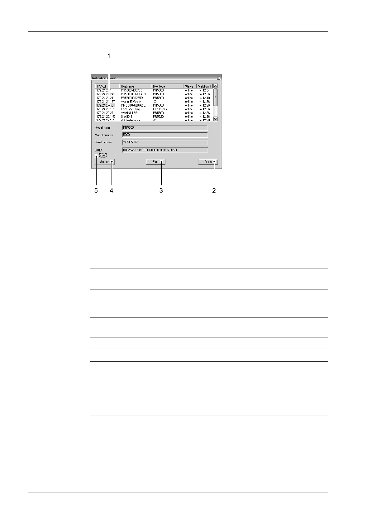
2.9.3 Searching the device in the network with "IndicatorBrowser"
The IP address can be found out using the "IndicatorBrowser" application (supplied on
CD-ROM) and via the "host name" of the device.
The "host name" is composed of the device name and the last 3 bytes of the MAC ID. A
label with the complete MAC ID is located on the outside of the device.
Host name: PR5900-6B6A5E
For this, the program must be installed and started on a notebook/PC.
EN-27 Minebea Intec
Process Controller Maxxis 5 PR 5900 2 Commissioning
Legend
No. Description
1 The program searches within the current network ID, e.g. 169.254. and 172.24.,
on all available network adapters in the PC (several possible/recommended,
e.g. LAN global/LAN local)
Result:
List of all connected devices with status: search??? – online - byebye – lost???
2 Click the button to open the "standard" Internet Browser, e.g. Microsoft Inter-
net Explorer, directly with the marked IP‑address.
3 Click the button to localize the associated device.
Short-term visual feedback from the device:
Regular running light in LED 1, 2, 3.
4 Click the button to re-start the network search run.
Waiting 2…3 minutes is essential!
5 Acoustic signal for each device that was detected as "online."
Note:
If the browser window remains empty after the minimum wait time, or if the expected
device is not listed, the network ID of the local notebook/PC must be checked and
changed, if necessary.
Only certain Minebea Intec devices are supported by the "indicator browser"!
Minebea Intec EN-28

2 Commissioning Process Controller Maxxis 5 PR 5900
2.9.4 Resetting the network address
Note:
Holding down (> 5 sec.) the reset key triggers a cold start:
- The settings are not changed.
- The database is emptied.
- Current process steps are deleted.
- The application must be restarted.
- The database must be restored.
Holding down (> 5 sec.) the rest key initiates a reset of the network settings to the
factory/default settings.
This means
- "DHCP" is activated.
- "Hostname" is initialized to, e.g. PR 5900-6B6A5E (type MAC-ID).
Example of MAC ID: 00-90-6C-6B-6A-5E
This ensures that a valid address for identication of the device in the network can be
assigned to the device from a server, see also Chapter 4.4.
Note:
The last 3 bytes of the MAC ID are displayed. A label with the complete MAC ID is located
on the outside of the device.
If the device is connected to an IT network (company network) with a DHCP server and if
the parameter [use DHCP] is activated in the menu [Operating] - [Default conguration]
- [Network parameters] (factory/default settings), no further actions are required except
for a waiting time of 2…3 minutes. Subsequently, a network connection is established
automatically (device <-> workstation/PC).
2.9.5 Operation using VNC
VNC (on the enclosed CD-ROM) stands for "virtual network computing" and is a program
for remote operation of computers.
The program distinguishes between the VNC server and VNC client (viewer). The server
program is part of the device software, the client program (viewer) must be run on the
notebook/PC in order to operate the device.
Note:
If the colors appear distorted, a better color format must be selected in the VNC viewer.
EN-29 Minebea Intec

.
WP-A
Max 3000g d= 0.1g
00
+
g
0g 3000g
22.08.2012 15:20:46
Anmelden
Process Controller Maxxis 5 PR 5900 2 Commissioning
For direct operation using the VNC program, the IP address (extended by :1) must be
specied when you run the program, e.g., 172.24.20.233:1.
Note:
In the device, the VNC access to certain notebooks/PCs in the network can be limited,
see Chapter 4.4.
The VNC user interface is displayed.
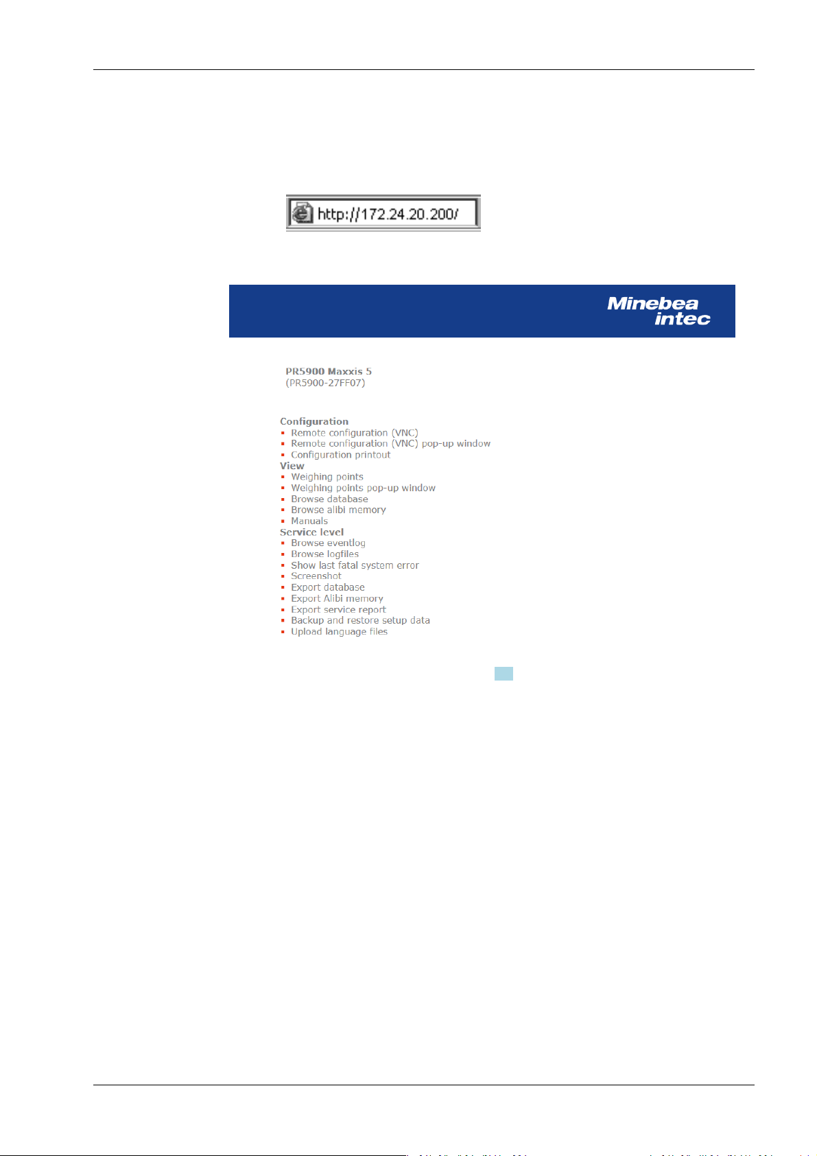
2.9.6 Operation via a web browser
Instead of the VNC viewer, the web browser can also be used directly.
The disadvantage is that an additional "Java" installation is required.
Minebea Intec EN-30
Note:
If the web browser supports the Java application, the device can be operated via[remote
conguration (VNC).]
If the web browser does not support the Java application, the menu items will be
inaccessible (grayed out).
In addition to VNC, this includes:
2 Commissioning Process Controller Maxxis 5 PR 5900
- easy operation for printing out the conguration
- easy operation for displaying and saving protocols
- easy operation for saving and loading conguration and calibration data
Example:
Enter the IP address in the Internet browser and conrm.
The web menu is displayed.
For description of the web menu see Chapter 3.9.
EN-31 Minebea Intec

WP-A
Max 3000g d= 0.1g
00
+
g
0g 3000g
22.08.2012 15:20:46
Login
WP-A
Max 3000g d= 0.1g
00
+
g
0g 3000g
22.08.2012 15:20:46
Login
A
B
C
Enter user name and password
User name
Password ********
Process Controller Maxxis 5 PR 5900 3 Operation and control
3 Operation and control
3.1 User login/logout
If user management is activated, the user must log in to operate and congure the device:
- User login, see Chapter 3.1.1.
- User logout, see Chapter 3.1.2.
3.1.1 User login
An authorized user must log in to start the application or enter parameters.
This window only appears if no user is logged in.
1. Press the [Login] soft key to log in as a specic user.
Note:
If the "default" user is active, a password does not need to be entered. The empty
entry window only needs to be conrmed to log in.
A login window appears.
2. Enter and conrm the user name.
3. Enter and conrm the password (access code).
Minebea Intec EN-32
Operating @admin
Application menu
Weighing
Check weighing
Device employed as terminal
Configuration
System menu
System setup
System information
System maintenance
Logout
Operating @admin
Application menu
Weighing
Check weighing
Device employed as terminal
Configuration
System menu
System setup
System information
System maintenance
Logout
3 Operation and control Process Controller Maxxis 5 PR 5900
Note:
Default setting: User name: admin; password: admin
The Operating window appears.
3.1.2 User Logout
In this menu item, the logged-in user is logged out.
Accessible via MENU - [Operation]- [Logout] .
1. Press the MENU key to switch to the operating menu.
The user who is currently logged in is shown in the top right-hand corner of the
display.
2. Press the [Logout] soft key to log out the user who is currently logged in.
If a password is required to log out the user (option activated in the user settings, see
Chapter 4.10), the entry window appears accordingly.
3.2 User management
EN-33 Minebea Intec
User management is deactivated by default, see Chapter 4.10.
By means of user management, access to various menu levels of the device can be
limited, if the necessity arises. This includes system setup, system maintenance, access
via the website and the various levels of the application (application-specic).

Process Controller Maxxis 5 PR 5900 3 Operation and control
Note:
User management can be activated optionally. However, it is not required for normal
operation.
During system installation and set-up, we recommend leaving user management
deactivated. This facilitates access to the various menus and to the website.
User management should usually be activated if:
- several people work with the device or have access to it.
- the aim is to prevent unauthorized people from making changes to the device or
from inuencing the processes controlled by the device.
3.3 Selecting the operating language
Factory settings: system language = operating language (display language)
The operating language can be changed as follows:
- Select and conrm the desired language in the menu [Operating]- [System setup]-
[Operating parameters]- [Display language] . Save the change using the [Save] soft
key, see also Chapter 4.3.
- Select and conrm in the menu [Operating]- [System setup]- [User management]-
- With the function keys F1 and F2, if a key has been assigned to [Change language] in
3.4 System menu
Under System menu in the Operating menu, the process controller is set up, information
is accessed and the system is managed.
[Create/copy/modify user]- [ Language] . Save the change using the [Save] soft key,
see also Chapter 4.10.1.
the menu [Operating]- [System setup]- [Operating parameters]- [F1/F2 key] , see
Chapter 4.3. The operating language can be changed from any menu.
Note:
When user management is activated, the operating language only changes once the
currently logged-in user logs out. It is only possible to switch languages immediately
using the F1 or F2 key.
Note:
The menu items under Application menu depend on the application in question and are
described in a separate operating manual.
Accessible via MENU key - [Operating].
Minebea Intec EN-34

Operating @admin
Application menu
Weighing
Check weighing
Device employed as terminal
Configuration
System menu
System setup
System information
System maintenance
Logout
3 Operation and control Process Controller Maxxis 5 PR 5900
System menu:
- [System setup], see Chapter 4.
All parameters relating to weighing electronics can be found under [Weighing
points].
- [Connected devices], see Chapter 4.1.
- [Date and time], see Chapter 4.2.
- [Operating parameters], see Chapter 4.3.
- [Network parameters], see Chapter 4.4.
- [Network share connections], see Chapter 4.5.
- [Fieldbus parameters], see Chapter 4.6.
- [Weighing points], see Chapter 4.7.
- [Display settings], see Chapter 4.8.
- [License settings], see Chapter 4.9.
- [User management], see Chapter 4.10.
- [Alibi memory], see Chapter 4.11.
- [System information], see Chapter 5.
- [Show version], see Chapter 5.1.
- [Show status], see Chapter 5.2.
- [Show alarm information], see Chapter 5.3.
- [Show HW options] (hardware options), see Chapter 5.4.
- [Show ModBus-TCP I/O module], see Chapter 5.5.
EN-35 Minebea Intec
- [Browse the Alibi memory], see Chapter 5.6.
- [Show calibration check number], see Chapter 5.7.
- [Show Pendeo data], see Chapter 5.8.
- [Show event log], see Chapter 5.9.
- [Print conguration settings], see Chapter 5.10.
- [System maintenance], see Chapter 6.
- [Backup], see Chapter 6.1.

Process Controller Maxxis 5 PR 5900 3 Operation and control
- [Restore], see Chapter 6.2.
- [Export], see Chapter 6.3.
- [Import], see Chapter 6.4.
- [Alibi memory maintenance], see Chapter 6.5.
- [SD card maintenance], see Chapter 6.6.
- [Create service report], see Chapter 6.7.
- [Shutdown & Power o] (switch o device), see Chapter 6.8.
- [Update software], see Chapter 6.9.
- [Factory reset], see Chapter 6.10.
- [Test hardware], see Chapter 6.11.
3.5 Help functions
The help function can be accessed from any parameter window using the ? key. A window
appears in which you can scroll up and down through the content using the cursor keys (↑,
↓, ▲, ▼). The window can be closed using the EXIT key.
3.6 Alibi memory
The individual functions of the Alibi memory are described in the following menu items:
- In the System setup menu, the conditions for a full Alibi memory are congured
- The Alibi memory is searched in the System information menu (menu [Operating]-
- In the System maintenance menu the records of the Alibi memory are exported or
Note:
The help text is given in English as a default if the corresponding language is
unavailable.
(menu [Operating]- [System setup]- [Alibi memory] ), see Chapter 4.11.
- [Tidy up records], see Chapter 4.11.1.
- [Delete] (complete Alibi memory), see Chapter 4.11.2.
[System information]- [Browse Alibi memory] ), see Chapter 5.6.
- [Search for specic date in Alibi memory], see Chapter 5.6.1.
- [Search for a given sequence number], see Chapter 5.6.2.
- [Status Alibi memory], show status, see Chapter 5.6.3.
printed and deleted if necessary ([Operating]- [System maintenance]- [Alibi memory
maintenance] ), see Chapter 6.5.
- [Export selection of records], the Alibi memory is exported to a storage medium
in XML format, see Chapter 6.5.1.
- [Export + tidy up selection of records], the Alibi memory is exported to a storage
medium in XML format and then deleted from the device, see Chapter 6.5.2.
- [Print selection of records], the Alibi memory is printed, see Chapter 6.5.3.
Minebea Intec EN-36

WP-A
Max 3000g d= 0.1g
00
+
g
Calibration @admin
Max
Scale interval
Dead load at
Max at
calibrated at
Sensitivity
3000.0 g
0.1 g
mV/V
mV/V
mV/V
µV/d
0.040368
1.177688
0.987884
0.471075
30000 d
1 d
102.832 g
3000.000 g
2516.5 g
98.14 cnt/d
New Modify
3 Operation and control Process Controller Maxxis 5 PR 5900
- [Print + tidy up selection of records], the Alibi memory is printed and then
deleted from the device, see Chapter 6.5.4.
3.7 Showing the calibration data
The calibration data is displayed in the format entered/determined during calibration.
Accessible via MENU – [Operating] - [System setup] - [Weighing points] - [Weighing
point x] - [Calib].
The calibration data is displayed:
- Scale interval and maximum capacity (Max)
- Scale interval(s)
- Dead load in weight and mV/V
- Weight and mV/V for maximum capacity
- Calibration weight* and corresponding mV/V
- Number of internal counts and voltage per scale interval
* After input with mV/V, the maximum capacity and the mV/V value entered are
displayed.
3.8 Increased resolution (10-fold) of the weight value
In the menu [Operating]- [System setup]- [Weighing points]- [Weighing point x] , the
weight is displayed with increased resolution (10-fold) for ve seconds after a weighing
point is selected, using the following keys:
- Key
- Function key F1 and/or F2 (if the function key has been assigned in the menu
[Operating]- [System setup]- [Operating parameters]- [F1/F2 key] ).
If the parameter [W&M] is selected for the weighing point, the weight value is marked as
an invalid weight with the symbol. After 2…3 seconds the display returns to normal
resolution.
3.9 Functions via the website
EN-37 Minebea Intec
If the device is connected to the network, it can be displayed e.g. in the "Windows"
operating system under [Network].
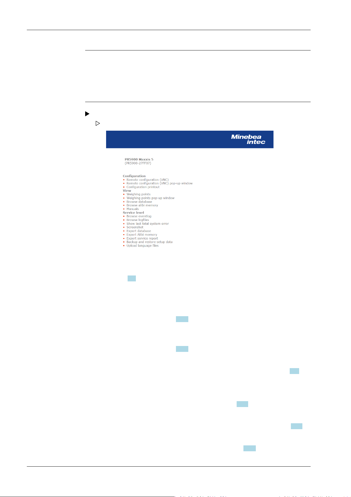
Process Controller Maxxis 5 PR 5900 3 Operation and control
Note:
If the web browser supports the Java application, the device can be operated via[remote
conguration (VNC).]
If the web browser does not support the Java application, the menu items will be
inaccessible (grayed out).
Double-click on the corresponding device symbol in the window.
The web menu is opened in the available Internet browser (in English only).
The device name entered appears in brackets below the header (in the menu
[Operating] - [System setup] - [Network parameters] - [Host name]), see
Chapter 4.4.
Conguration:
[Remote conguration (VNC)]
For device operation using the VNC program without additional installation of
the VNC client, see Chapter 2.9.5.
[Remote conguration (VNC) pop-up window]
For device operation using the VNC program without additional installation of
the VNC client, see Chapter 2.9.5.
[Conguration printout]
Can be used for printing the conguration data as a text le, see Chapter 10.1.
View:
[Weighing Points]
Displays the weighing points in a table, see Chapter 3.9.1.
[Weighing Points Pop-up Window]
Displays the weighing points in a table in a separate window, see Chapter 3.9.1.
[Browse Database]
Browse the application-specic database, see Chapter 3.9.2.
Minebea Intec EN-38

3 Operation and control Process Controller Maxxis 5 PR 5900
[Browse Alibi memory]
Browse the Alibi memory, see Chapter 3.9.3.
[Manuals]
PDF les are saved on the SD card (only SD cards from Minebea Intec supplied
with the device), see Chapter 3.9.4.
Service level:
Note:
Some functions require additional rights. When user management is activated,
the logged in user must have rights for [Use functions on the website] and the
appropriate system rights.
[Browse eventlog]
Browse event log, see Chapter 3.9.5.
[Browse logles]
Browse, display, copy, print log les, see Chapter 3.9.6.
[Show last fatal system error]
Display, copy, print the error log, see Chapter 3.9.7.
[Screenshot]
Saves a screenshot, see Chapter 3.9.8.
[Export database]
Export database as XML le, see Chapter 3.9.9.
[Export Alibi memory]
Export Alibi memory as XML le, see Chapter 3.9.3.
[Export service report]
Export service report as XML le, see Chapter 3.9.11.
[Backup and restore setup data]
Create backup of setup data and restore setup data, see Chapter 3.9.12.2.
[Upload language les]
Uploads the language les to the device, see Chapter 3.9.13.
3.9.1 Display weighing points in a table
Note:
If the web browser does not support the Java application, the menu items will be
inaccessible (grayed out).
In this web menu item, the weighing points are displayed in a table.
Accessible via the web menu – [Weighing Points].
1. Click [Weighing Points] in the web menu.
EN-39 Minebea Intec
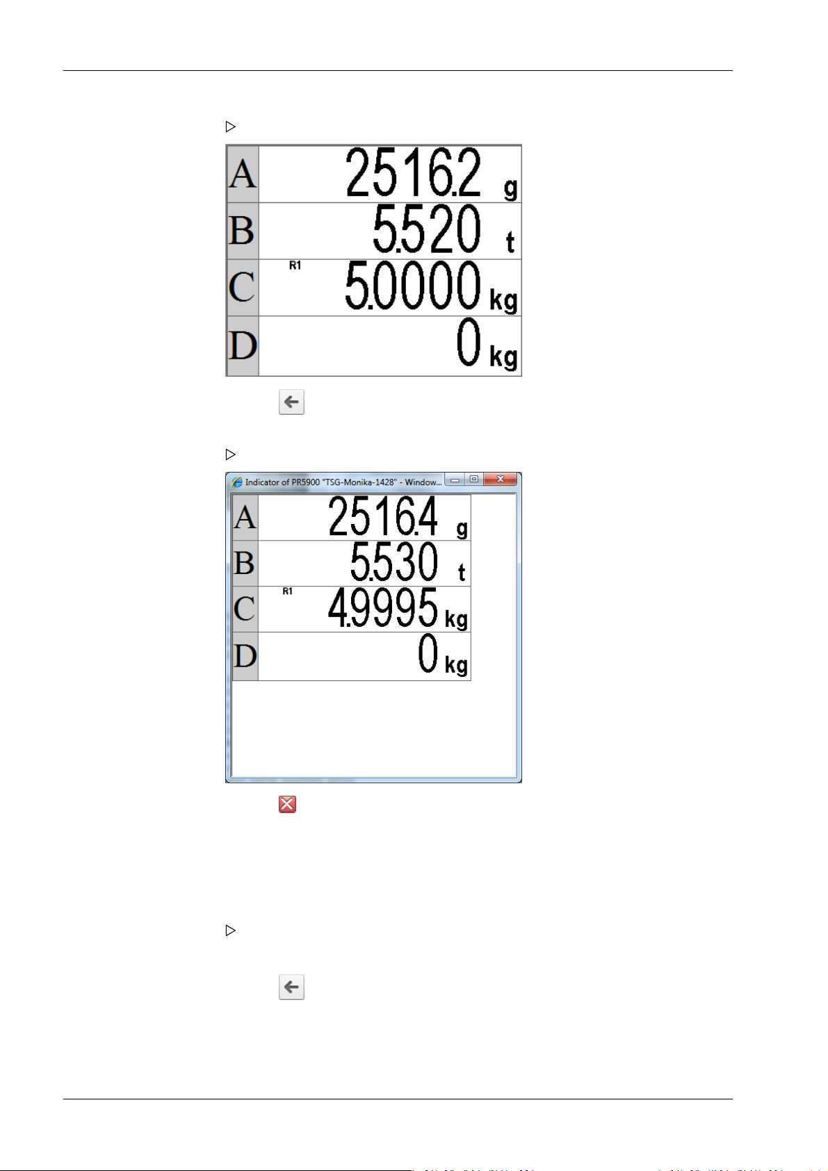
Process Controller Maxxis 5 PR 5900 3 Operation and control
A table containing all four weighing points appears.
2. Click the symbol to return to the web menu.
3. In the web menu, click [Weighing Points Pop-up Window].
A table containing all four weighing points appears in a separate window.
4. Click the symbol to return to the web menu.
3.9.2 Browse database
In this web menu item, an application-specic database is searched.
Accessible via the web menu - [Browse Database].
1. Click [Browse Database] in the web menu.
A table with entries appears.
Click on the entries in the table to display the corresponding content.
2. Click the symbol to return to the web menu.
3.9.3 Browsing the Alibi memory
In this web menu item, the Alibi memory is searched via a calendar window.
Minebea Intec EN-40

3 Operation and control Process Controller Maxxis 5 PR 5900
Accessible via the web menu - [Browse Alibi Memory].
1. Click [Browse Alibi Memory] in the web menu.
A calendar window appears.
Past months are underlined. The current day is displayed in bold in the "Day" row and
column.
The number of saves is given in parentheses ().
2. Click on the desired date.
A table is displayed for each save.
3. Click the symbol to return to the web menu.
3.9.4 Displaying manuals
In this web menu item, the saved manuals that are located on the SD card supplied with
the device by Minebea Intec are displayed.
Accessible via the web menu - [Manuals].
1. Click [Manuals] in the web menu.
Several les are listed. Click on a le to view its contents.
2. Click the symbol to return to the web menu.
3.9.5 Browse the event log
In this web menu item, the event log is displayed in the event logger window.
Accessible via the web menu - [Browse Eventlog].
The log is a table showing the individual events on the device. This log can be used to
analyze any possible problems.
EN-41 Minebea Intec

Process Controller Maxxis 5 PR 5900 3 Operation and control
The three event types are:
- Error
- Info
- Warning
The four source types are:
- [Fatal error]
- [Setup]
- [Power system]
- [Indicator]
1. Click [Browse Eventlog] in the web menu.
The "Eventlogger” window appears.
2. Click the symbol to return to the web menu.
3.9.6 Browse log les
In this web menu item, the log les can be searched, displayed, copied and printed.
Log les can be used to analyze any possible problems.
Accessible via the web menu - [Browse logles]
1. Click [Browse logles] in the web menu.
Several les are listed. Click on a le to view its contents.
2. Click the symbol to return to the web menu.
3.9.7 Displaying a log of the last system error
In this web menu item, the log of the last system error can be displayed, copied and
printed.
Logs can be used to analyze any possible problems.
Note:
This data is also contained in the service report.
Minebea Intec EN-42
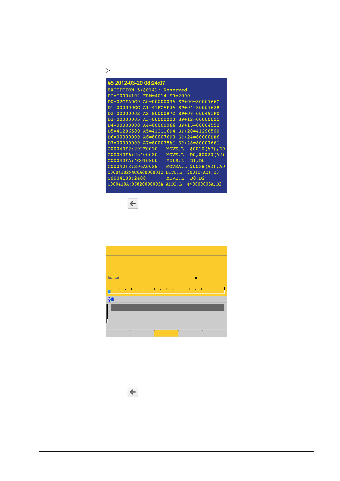
WP-A
Max 3000g d= 0.1g
Min 2g
7
16
N
–
g
2g 3000g
Single weighing point @admin
Limit 3
Net
Tare
A
A
0.0 - 0.0 g
<-61.7 g>
60.9 g
Set tare
3 Operation and control Process Controller Maxxis 5 PR 5900
Accessible via the web menu - [Show last fatal system error]
1. Click [Show last fatal system error] in the web menu.
The last saved system error is displayed.
3.9.8 Screenshot
2. Click the symbol to return to the web menu.
In this web menu item, the device screenshot is displayed and can be saved if required.
Accessible via the web menu - [Screenshot].
1. Congure the corresponding display (here: Weighing) on the device.
2. Click [Screenshot] in the web menu.
3. The device display is shown on the notebook/screen.
4. Right-click on the display and save to the desired folder via the [Save image as…]
option.
3.9.9 Export database
EN-43 Minebea Intec
5. Click the symbol to return to the web menu.
In this web menu item, the export of a database is saved in a selected directory as an XML
le.
Accessible via the web menu - [Export database].
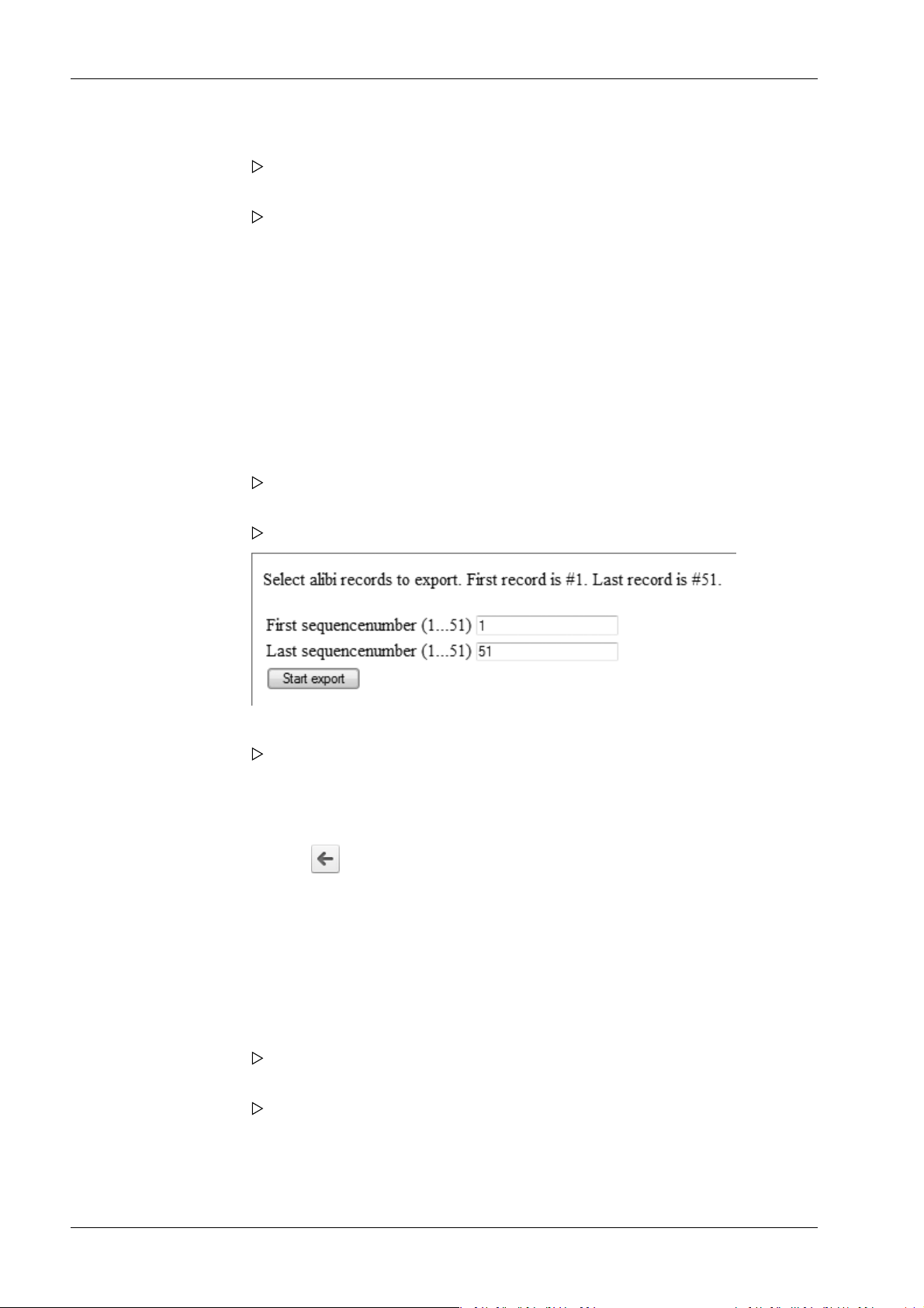
Process Controller Maxxis 5 PR 5900 3 Operation and control
1. Click [Export database] in the web menu.
If applicable, an input window appears.
2. If applicable, enter user name and password and conrm.
The le download window of the Internet browser appears.
3. Click [Save].
4. Select a directory in which to save the XML le.
5. Click [Save].
3.9.10 Export Alibi memory
In this web menu item, the export of the Alibi memory is saved in a selected directory as
an XML le.
Accessible via the web menu - [Export Alibi memory].
Example: "InternetExplorer"
1. Click [Export Alibi memory] in the web menu.
If applicable, an input window appears.
2. If applicable, enter user name and password and conrm.
A page appears on which the Alibi entries to be exported can be selected.
3. Enter the desired range of records (here: 1…51) and click [Start export].
The le download window of the Internet browser appears.
4. Click [Save].
5. Select a directory in which to save the XML le.
6. Click [Save].
7. Click the symbol to return to the web menu.
3.9.11 Export service report
In this web menu item, the export of the service report is saved in a selected directory as
an XML le. In the event of an error, the le can be sent to customer service.
Accessible via the web menu - [Export service report].
Example: "InternetExplorer"
1. Click [Export service report] in the web menu.
If applicable, an input window appears.
2. If applicable, enter user name and password and conrm.
The le download window of the Internet browser appears.
3. Click [Save].
4. Select a directory in which to save the XML le.
5. Click [Save].
Minebea Intec EN-44
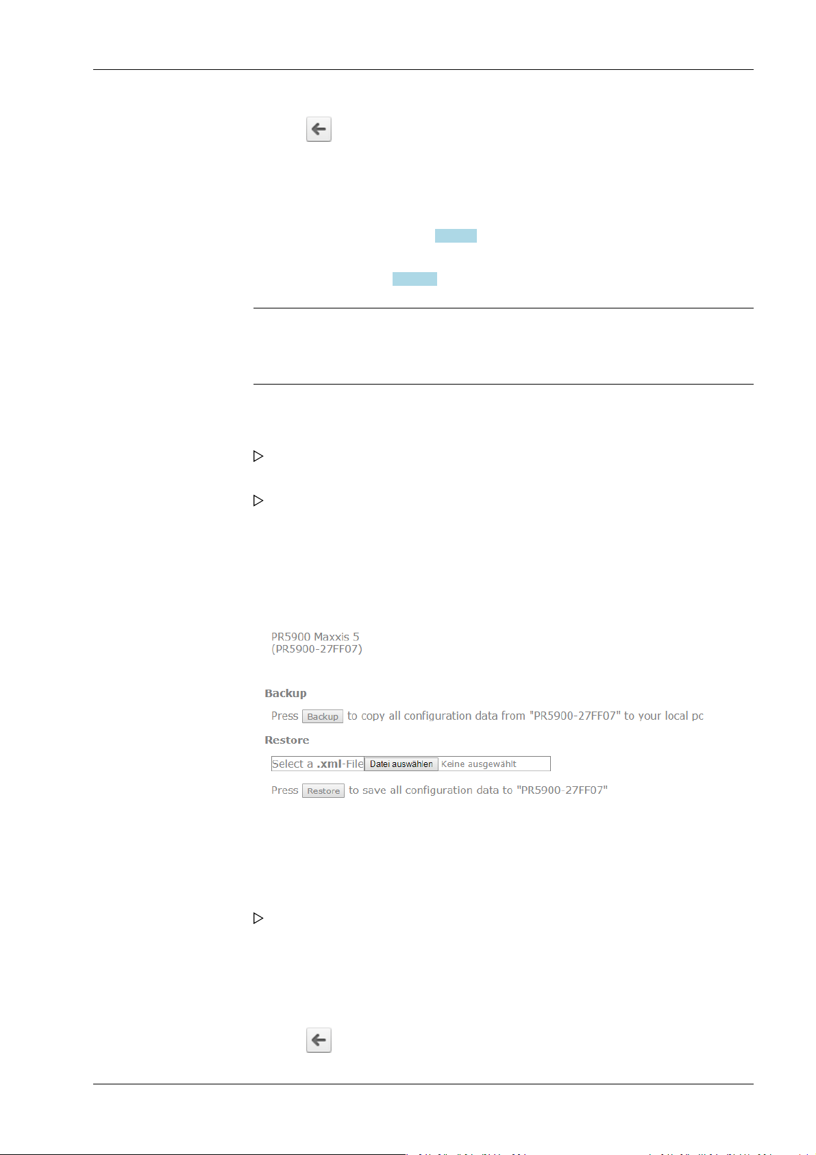
3 Operation and control Process Controller Maxxis 5 PR 5900
6. Click the symbol to return to the web menu.
3.9.12 Backup and restore setup data
In this web menu item,
- [Backup] can be used to save the setup, user, calibration and application data as a
backup on the PC, see Chapter 3.9.12.1.
- [Restore] can be used to restore the setup, user, calibration and application data on
the device, see Chapter 3.9.12.2.
Note:
This function cannot be used to back up the database on the PC and restore it on
the device. This is only possible in the menu [Operating]- [System maintenance] .
Accessible via the web menu - [Backup and restore setup data].
1. Click [Backup and restore setup data] in the web menu.
If applicable, an input window appears.
2. If applicable, enter user name and password and conrm.
The backup and restore menu appears.
3.9.12.1 Backup
In this web menu item, a backup with the setup, user, calibration and application data is
created on the PC.
Accessible via the web menu – [Backup and restore setup data] - [Backup].
Backup and restore menu.
1. Click [Backup] to create a backup.
Example: "InternetExplorer"
The le download window of the Internet browser appears.
2. Click [Save].
3. Select a directory in which to save the XML le.
4. Click [Save].
The backup has been saved in the selected directory.
5. Click the symbol to return to the web menu.
EN-45 Minebea Intec

Process Controller Maxxis 5 PR 5900 3 Operation and control
Possible error messages, see Chapter 3.9.12.3
3.9.12.2 Restore
In this web menu item, the setup, user, calibration, and application data is restored on the
device.
Accessible via the web menu – [Backup and restore setup data] - [Restore].
1. Click [Browse] to select an XML le for restoring.
2. Select the XML le (e.g. setup-PR5900 27FF07-20130729-082010.xml).
3. Click [Open].
4. Click [Restore].
5. Click the symbol to return to the web menu.
3.9.12.3 Error messages
In the web menu item Backup/Restore, the following error messages may appear when
backing up or restoring the setup data:
Example: "InternetExplorer"
The le upload window of the Internet browser appears.
The le name is displayed in the selection window.
The setup data is saved on the device.
Possible error messages, see Chapter 3.9.12.3
This message appears if the user is not logged out.
Minebea Intec EN-46

3 Operation and control Process Controller Maxxis 5 PR 5900
This message appears if a CAL switch is closed and/or if [Operating] - [System setup] [Weighing points] - [Weighing point x] - [Parameters] - [Settings locked] is active.
3.9.13 Loading language les
In this web menu item, the language les are loaded onto the device.
Note:
This function allows translations to be tested during development. The les are only
available in the working memory and will be lost when the next cold start occurs.
For permanent storage, the language les must be loaded onto the device together
with the application in the menu [Operating] - [System maintenance] - [Update
software] (see Chapter 6.9).
Accessible via the web menu - [Upload Language Files].
1. Click [Upload Language Files] in the web menu.
A selection window opens.
2. Click [Browse], select the corresponding "mo les," and click [upload] to load the les
onto the device.
3. Click the symbol to return to the web menu.
3.10 BIOS BOOT menu
If the device cannot perform a normal system start, the BIOS BOOT menu must be used:
- Open BIOS BOOT menu, see Chapter 3.10.1.
- BIOS BOOT menu in blackbox device, see Chapter 3.10.2.
EN-47 Minebea Intec

BIOS BOOT MENU
Select device boot mode
Warmstart
Coldstart
Recover
(continue from powerfail)
(reset application)
(fix unbootable system)
Process Controller Maxxis 5 PR 5900 3 Operation and control
- System messages in blackbox device, see Chapter 3.10.3.
Note:
The BIOS BOOT menu is in English, regardless of the selected language settings.
3.10.1 Open BIOS BOOT menu
The following modes are available for a system start in the BIOS BOOT menu:
- Warm start [Warm start], see Chapter 3.10.1.1.
- Cold start [Cold start], see Chapter 3.10.1.2.
- Restore [Recover], see Chapter 3.10.1.3.
Requirements:
- The supply voltage is disconnected.
- All LEDs have gone out.
If this is not the case, the connection to the standby battery must be interrupted with the
power supply disconnected (pull the plug out carefully). Restore the connection
afterwards.
Note:
The battery is located beneath the weighing electronics board WP A, see PR 5900
installation manual.
Accessible via STOP key.
1. Hold down the STOP key.
2. Switch on the supply voltage.
The message "STOP key detected" appears.
3. Release the STOP key.
The BIOS BOOT menu appears.
3.10.1.1 Warm start
Minebea Intec EN-48
Perform a system start via the warm start mode in the BIOS BOOT menu.

BIOS BOOT MENU
Select device boot mode
Warmstart
Coldstart
Recover
(continue from powerfail)
(reset application)
(fix unbootable system)
BIOS BOOT MENU
Select device boot mode
Warmstart
Coldstart
Recover
(continue from powerfail)
(reset application)
(fix unbootable system)
3 Operation and control Process Controller Maxxis 5 PR 5900
Accessible via STOP key - [Warm start].
Conrm [Warm start] with the ► key/OK.
The device starts up in the same way it does after a power failure.
Note:
3.10.1.2 Cold start
This menu item is disabled if a warm start is not possible. A warm start may not
be possible for the following reasons:
- Fatal system error
- Faulty battery
Perform a system start via the cold start mode in the BIOS BOOT menu.
Accessible via STOP - [Cold start] key.
EN-49 Minebea Intec
Select [Cold start] with the ▼ key and conrm with the ► key/OK.
The device starts, the database is cleared, and the application restarts.
Note:
If the device starts successfully, an existing database backup, if there is one, can
be re-imported (see Chapter 6.2).

BIOS BOOT MENU
Select device boot mode
Warmstart
Coldstart
Recover
(continue from powerfail)
(reset application)
(fix unbootable system)
CAL switch 2 is closed!
Please open the cal switch and press
any key.
Press ███EXIT to cancel.
Process Controller Maxxis 5 PR 5900 3 Operation and control
3.10.1.3 Restore Replace or repair a faulty application via the restore mode (Recover) in the BIOS BOOT
menu:
- Restore from SD card [Restore last Software from SD-Card], see Chapter 3.10.1.3.1
- Load software with FlashIt! [Listen from FlashIt], see Chapter 3.10.1.3.2.
- Cold start in safe mode [Cold start in safe mode], see Chapter 3.10.1.3.3.
Accessible via STOP - [Recover] key.
1. Select [Recover] with the ▼ key and conrm with the ► key/OK.
The overwrite protection statuses are checked (CAL switches and parameters
[Settings locked]).
This message appears if at least one CAL switch is closed.
2. Open the CAL switch and press any key to check the statuses again.
Or: Press the EXIT key to cancel the process and return to the BIOS menu.
Minebea Intec EN-50

Settings are locked for W&M WP A.
Continuing will change the calibration
check number 3004174066!
Press▐█, C ▐█, C ▐█, C and then ██▌OK to clear
W&M and settings locked.
Press ███ EXIT to cancel.
ERROR RECOVERY MENU
Select error recovery option
Restore last software from SD-Card
Listen for FlashIt!
Coldstart in safe mode
3 Operation and control Process Controller Maxxis 5 PR 5900
This message appears if the [W&M] parameter has been set to another value besides
[none] for at least one weighing point and [Settings locked] has been activated.
3. Press the C key three times and then press the OK key to reset the [W&M] parameter
and [Settings locked].
The calibration check number changes.
Or: Press the EXIT key to cancel the process and return to the BIOS BOOT menu.
4. If all checks have been carried out, the troubleshooting menu (ERROR RECOVERY
menu) appears.
3.10.1.3.1 Restore from SD card
Replace a faulty application in the BIOS BOOT menu via restore last software from SD
card.
Accessible via the STOP key [Recover]- [Restore last Software from SD-Card] .
EN-51 Minebea Intec

ERROR RECOVERY MENU
Select error recovery option
Restore last software from SD-Card
Listen for FlashIt!
Coldstart in safe mode
ERROR RECOVERY MENU
Select error recovery option
Restore last software from SD-Card
Listen for FlashIt!
Coldstart in safe mode
Process Controller Maxxis 5 PR 5900 3 Operation and control
Conrm [Restore last Software from SD-Card] using the ► key/OK.
The last saved software image (BIOS, rmware, and application) is restored in the
device.
3.10.1.3.2 Load software with FlashIt!
Load a faulty application via software with FlashIt! in the BIOS BOOT menu Replace
(Listen from FlashIt).
Accessible via the STOP key [Recover]- [Listen from FlashIt] .
3.10.1.3.3 Cold start in safe mode
Minebea Intec EN-52
Select [Listen from FlashIt] with the ▼ key and conrm with the ► key/OK.
It is now possible to load software on the device via the network using the
"FlashIt!" program, see also Chapter 6.9.3.
Repair a faulty application via cold start in the BIOS BOOT menu.
Accessible via the STOP key - [Recover]- [Cold start in safe mode] .
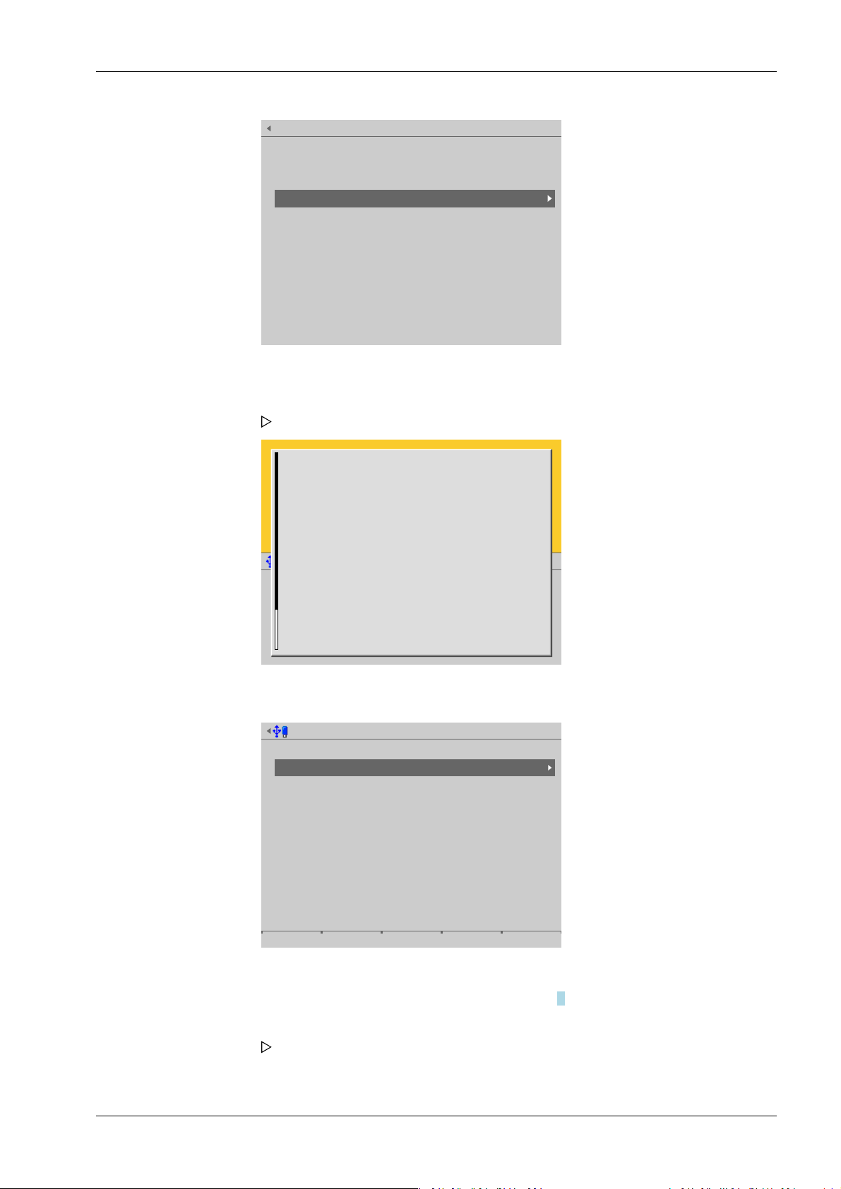
ERROR RECOVERY MENU
Select error recovery option
Restore last software from SD-Card
Listen for FlashIt!
Coldstart in safe mode
Safe mode activated
All settings have been ignored until now.
In the maintenance level you can
-[Export a service report]
To record the faulty conditions for later inspection.
-[Backup settings]
Although setting were not loaded, you can make a
backup for later review.
-[Restore settings]
Load settings from another backup to return the device
to some wellknown settings.
-[Factory reset]
System maintenance (safe mode)
Backup
Restore
Export
Import
Alibi memory maintenance
SC card maintenance
Create service report
Shutdown & Power off
Update software
Factory reset
Test hardware
3 Operation and control Process Controller Maxxis 5 PR 5900
1. Select [Cold start in safe mode] with the ▼ key and conrm with the ► key/OK.
The device starts in a mode where all settings (even language settings) are ignored.
A help window appears.
EN-53 Minebea Intec
2. Press the EXIT key to close the help window and switch to the system maintenance
menu (ERROR RECOVERY menu).
3. Select the desired menu item with the ▼ key and conrm with the ► key/OK.
The rest of the procedure is described in Chapter 6.
4. Press the EXIT key to exit the system maintenance menu (ERROR RECOVERY menu).
A prompt window appears.

Operation
?
Do a cold start to finish safe mode?
Cancel Continue
Process Controller Maxxis 5 PR 5900 3 Operation and control
5. Press the [Cancel] soft key to select additional menu items in the system maintenance
menu (ERROR RECOVERY menu) if necessary.
6. Press the [Continue] soft key to perform a cold start.
3.10.2 BIOS BOOT menu in blackbox device
Since the BIOS cannot communicate with the remote terminal or VNC client, individual
menu items are triggered via the reset key and displayed via LED:
- The BIOS BOOT menu is automatically activated when ve restarts fail one after the
other.
- The BIOS BOOT menu can be accessed manually if the reset key is held down while
the device is being switched on.
If the BIOS BOOT menu is activated, the LED ashes quickly and an acoustic signal sounds
repeatedly.
The following menu items can be selected in the BIOS BOOT menu via the reset key:
Menu item Reset key LED
Cold start press once ashes once o------o------o--Safe mode press again ashes twice oo-----oo-----oo--Restore software from SD
card
1. Press the reset key repeatedly to select other menu items.
2. Press the "Reset" button for as long as it takes (at least 2 seconds) for the LED to
illuminate continuously to conrm the selection.
3.10.3 System messages in blackbox device
The BIOS writes the messages to the temporary memory of the rmware.
press again ashes three
times
ooo----ooo----ooo---
Minebea Intec EN-54

WP-A
Max 3000kg d= 1kg
831
+
kg
0kg 3000kg
22.08.2012 15:20:46
i
Bios messages
Update Firmware programmed
Update Application programmed
skip Lables
Update Bios already programmed
Ok
WP-A
Max 3000kg d= 1kg
831
+
kg
0kg 3000kg
22.08.2012 15:20:46
Fatal system errror
#282 : 2014–09–01–07:18:39–UTC
EXCETION 71($11C): EdgePort7
PC=C0008CE6 FRM=411C SR=2704
D0=00000000 A0=800076AA SP+00=C00278FE
D1=800076AA A1=00000004 SP+04=00071838
D2=80007690 A2=C00322A0 SP+08=00000000
D3=00000062 A3=00000000 SP+12=00000002
D4=00026883 A4=00000001 SP+16=800076F0
D5=000076A8 A5=41790A40 SP+20=C0027A10
D6=00000000 A6=800076F0 SP+24=80000EFE
D7=CF306089 A7=80007670 SP+28=00004552
C0008CD6:4A80 TST.T D0
C0008CD8:6762 BEQ.B $C0008D00
C0008CDA:4200 CLR.B D0
C0008CDC:13C010000000 MOVE.B
D0, $10000000
C0008CE2:4E71 NOP
C0008CE4:4E71 NOP
C0008CE6:4E71 NOP
C0008CE8:4E71 NOP
C0008CEA:4E71 NOP
C0008CEC:4E71 NOP
C0008CEE:4E71 NOP
3 Operation and control Process Controller Maxxis 5 PR 5900
These messages are displayed once the device has booted successfully.
Note:
The BIOS messages are always in English, regardless of the selected language settings.
A cold start is carried out if a fatal system error occurs.
This message appears on the display after the device has booted.
EN-55 Minebea Intec

Operating @admin
Application menu
Weighing
Check weighing
Device employed as terminal
Configuration
System menu
System setup
System information
System maintenance
Logout
System setup @admin
Connected devices
Date & Time
Operating parameters
Network parameters
Network share connections
Fieldbus parameters
Weighing points
Display settings
License settings
User management
Alibi memory
Process Controller Maxxis 5 PR 5900 4 System setup
4 System setup
In the system setup menu (under System menu), the system is set up and congured.
- [Connected devices], see Chapter 4.1.
- [Date and time], see Chapter 4.2.
- [Operating parameters], see Chapter 4.3.
- [Network parameters], see Chapter 4.4.
- [Network share connections], see Chapter 4.5.
- [Fieldbus parameters], see Chapter 4.6.
- [Weighing points], see Chapter 4.7.
- [Display settings], see Chapter 4.8.
- [License settings], see Chapter 4.9.
- [User management], see Chapter 4.10.
- [Alibi memory], see Chapter 4.11.
Accessible via MENU – [Operating] - [System setup].
Select and conrm [System setup].
The system setup menu opens.
Minebea Intec EN-56

System setup @admin
Connected devices
Date & Time
Operating parameters
Network parameters
Network share connections
Fieldbus parameters
Weighing points
Display settings
License settings
User management
Alibi memory
Connected devices @admin
General devices
Remote display
ModBus-RTU master
PC via EW-Com
Printer
Remote terminal
Barcode scanner
Add. application devices
Ticket printer
Printer 2
Interface
(not assigned)
(Not assigned)
(Not assigned)
(Network printer)
(C1/CX1)
(Remote terminal TTY)
Interface
(Network printer)
(Not assigned)
4 System setup Process Controller Maxxis 5 PR 5900
4.1 Connected devices
In this menu item (under System setup), the parameters for the connected devices are
congured.
General devices
- [Remote display], see Chapter 4.1.1.
- [ModBus-RTU master], see Chapter 4.1.2.
- [PC via EW-Com], see Chapter 4.1.3.
- [Printer], see Chapter 4.1.4.
- [Remote terminal], see Chapter 4.1.5.
- [Barcode scanner], see Chapter 4.1.6.
Accessible via MENU - [Operating]- [System setup]- [Connected devices] .
4.1.1 Remote display
EN-57 Minebea Intec
Conrm [Connected devices].
In this menu item (under Connected devices), the parameters for a remote display are
congured. A serial interface is used for connection.
Accessible via MENU - [Operating] - [System setup]- [Connected devices]- [Remote
display] .
The connected devices menu opens.
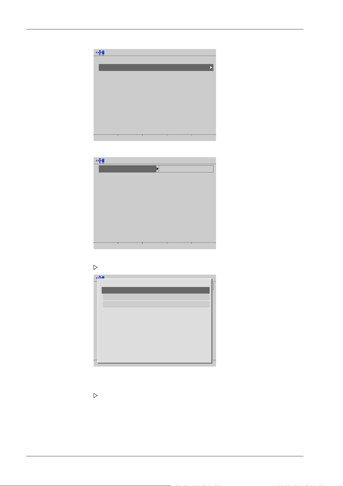
Connected devices @admin
General devices
Remote display
ModBus-RTU master
PC via EW-Com
Printer
Remote terminal
Barcode scanner
Add. application devices
Ticket printer
Printer 2
Interface
(not assigned)
(Not assigned)
(Not assigned)
(Network printer)
(C1/CX1)
(Remote terminal TTY)
Interface
(Network printer)
(Not assigned)
Remote display @admin
Interface not assigned
Save
Remote display @admin
Interface not assigned
Save
Not assigned
Built-in RS-232
Built-in RS-485
Option-2 RS-485-A
Option-2 RS-485-B
Process Controller Maxxis 5 PR 5900 4 System setup
1. Conrm [Remote display].
2. Select and conrm [Interface].
A selection window opens.
Inactive interfaces are grayed out.
3. Select and conrm the desired interface.
Minebea Intec EN-58
A selection window opens.
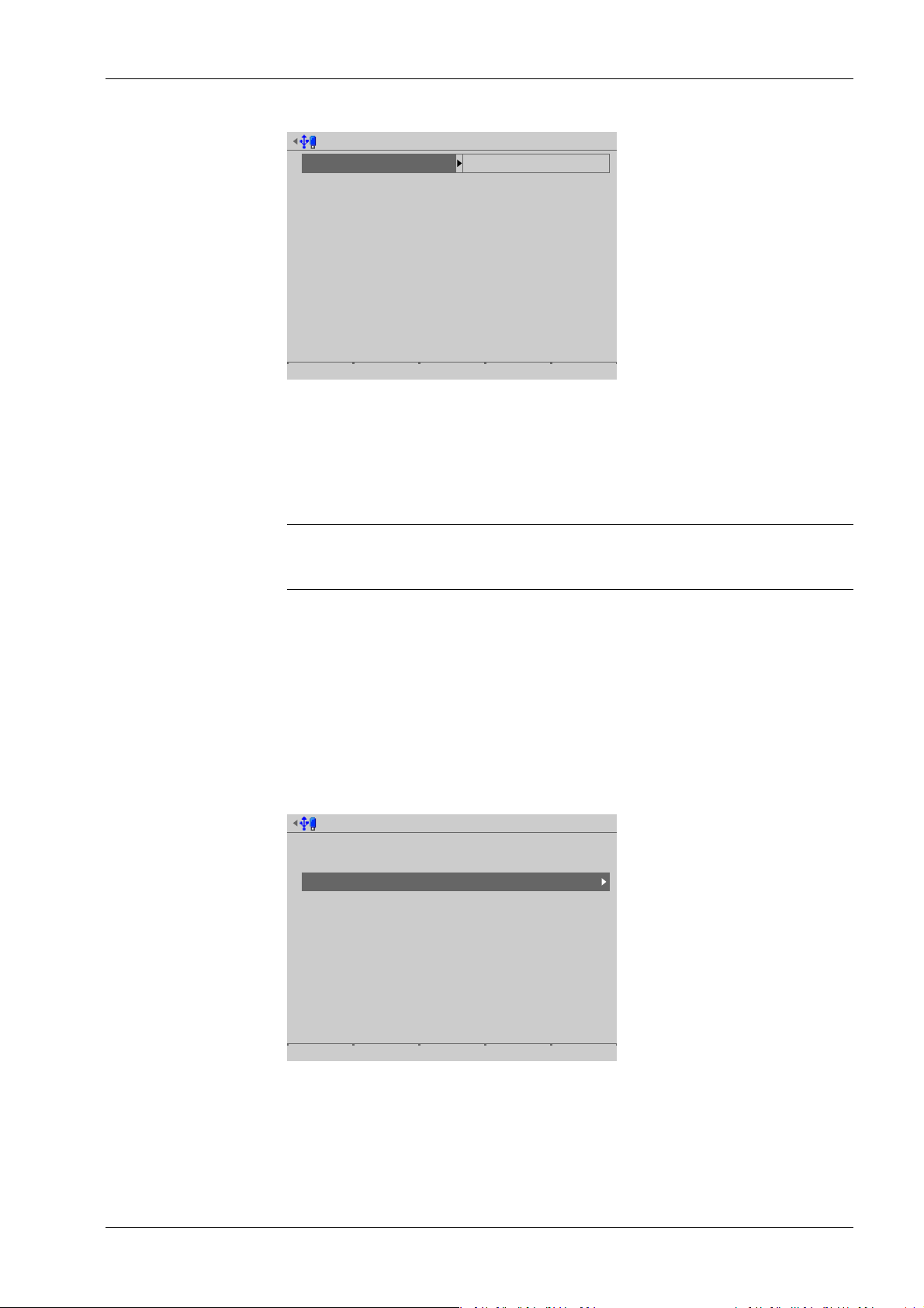
Remote display @admin
Interface
Baudrate
Data bits
Parity
Stop bits
Built-in RS-232
9600 baud
7 data bits
even parity
1 stop bit
Default Save
Connected devices @admin
General devices
Remote display
ModBus-RTU master
PC via EW-Com
Printer
Remote terminal
Barcode scanner
Add. application devices
Ticket printer
Printer 2
Interface
(not assigned)
(Not assigned)
(Not assigned)
(Network printer)
(C1/CX1)
(Remote terminal TTY)
Interface
(Network printer)
(Not assigned)
4 System setup Process Controller Maxxis 5 PR 5900
Inactive parameters are grayed out.
4. Select and conrm the desired parameters.
Only the baud rate can be adjusted here.
Selection: 300, 600, 1200, 2400, 4800, 9600, 19200 baud
Note:
The selected value must match the value of the connected device.
5. Press the [Save] soft key to save the settings.
4.1.2 ModBus-RTU master
In this menu item (under Connected devices), the parameters for a ModBus-RTU master
are congured. A serial interface is used for connection.
A maximum of two digital scale protocols are possible if [Operating] - [System setup] [Connected devices] - [ModBus-RTU master] has been selected in the menu.
Accessible via MENU - [Operating]- [System setup]- [Connected devices]- [ModBus-RTU
master] .
EN-59 Minebea Intec
1. Select and conrm [ModBus-RTU master].

ModBus-RTU master @admin
Interface not assigned
Save
ModBus-RTU master @admin
Interface not assigned
Save
Not assigned
Built-in RS-232
Built-in RS-485
Option-2 RS-485-A
Option-2 RS-485-B
ModBus-RTU master @admin
Interface
Baudrate
Data bits
Parity
Stop bits
ModBus Slave ID
Built-in RS-485
9600 baud
8 data bits
no parity
1 stop bit
1
Default Save
Process Controller Maxxis 5 PR 5900 4 System setup
2. Select and conrm [Interface].
A selection window opens.
Inactive interfaces are grayed out.
3. Select and conrm the desired interface.
A selection window opens.
Inactive parameters are grayed out.
4. Select and conrm the desired parameters.
[Baud rate]
Baud rate of the data transfer.
Selection: 300, 600, 1200, 2400, 4800, [9600], 19200, 38400, 57600, 115200 baud
Minebea Intec EN-60

Connected devices @admin
General devices
Remote display
ModBus-RTU master
PC via EW-Com
Printer
Remote terminal
Barcode scanner
Add. application devices
Ticket printer
Printer 2
Interface
(not assigned)
(Not assigned)
(Not assigned)
(Network printer)
(C1/CX1)
(Remote terminal TTY)
Interface
(Network printer)
(Not assigned)
PC via EW-Com @admin
Interface not assigned
Save
4 System setup Process Controller Maxxis 5 PR 5900
Note:
The selected value must match the value of the connected device.
[Parity]
Parity check for detecting errors during data transmission.
Selection: no parity, odd parity, even parity
[Modbus Slave ID]
Input: an address from 1…255
5. Press the [Save] soft key to save the settings.
4.1.3 PC via EW-Com
In this menu item (under Connected devices), the parameters for a PC via EW-Com are
congured. A serial interface is used for connection.
Accessible via MENU - [Operating] - [System setup]- [Connected devices]- [PC via EWCom] .
1. Select and conrm [PC via EW-Com].
EN-61 Minebea Intec
2. Select and conrm [Interface].
A selection window opens.

PC via EW-Com @admin
Interface not assigned
Save
Not assigned
Built-in RS-232
Built-in RS-485
Option-2 RS-485-A
Option-2 RS-485-B
PC via EW-Com @admin
Interface
Protocol
Baudrate
Data bits
Parity
Stop bits
EW-Com slave ID
Built-in RS-485
EW-Com V1
9600 baud
8 data bits
even parity
1 stop bit
A
Default Save
Process Controller Maxxis 5 PR 5900 4 System setup
Inactive interfaces are grayed out.
3. Select and conrm the desired interface.
A selection window opens.
Inactive parameters are grayed out.
4. Select and conrm the individual parameters.
[Protocol]
Transmission protocol
Selection: EW-Com V1, EW-Com V2, EW-Com V3
V1 for old communication programs
V2 for recipe controller
V3 for OPC
[Baud rate]
Baud rate of the data transfer.
Selection: 300, 600, 1200, 2400, 4800, [9600], 19200, 38400, 57600, 115200 baud
Note:
The selected value must match the value of the connected device.
Minebea Intec EN-62

Connected devices @admin
General devices
Remote display
ModBus-RTU master
PC via EW-Com
Printer
Remote terminal
Barcode scanner
Add. application devices
Ticket printer
Printer 2
Interface
(not assigned)
(Not assigned)
(Not assigned)
(Not assigned)
(C1/CX1)
(Remote terminal TTY)
Interface
(Network printer)
(Not assigned)
Printer @admin
Interface not assigned
Test print Save
4 System setup Process Controller Maxxis 5 PR 5900
[Data bits]
Groups of data bits.
Selection: 7 data bits, [8 data bits]
[EW-Com slave ID]
Input: Address from A to Z.
5. Press the [Save] soft key to save the settings.
4.1.4 Printer
In this menu item (under Connected devices), the parameters for a printer are
congured.
- [Serial printer], see Chapter 4.1.4.1.
- [Network printer], see Chapter 4.1.4.2.
- [Network share connection] (shared directory), see Chapter 4.1.4.3.
- [USB printer], see Chapter 4.1.4.4.
- [USB folder], see Chapter 4.1.4.5.
Accessible via MENU - [Operating] - [System setup]- [Connected devices]- [Printer] .
1. Select and conrm [Printer].
EN-63 Minebea Intec
2. Select and conrm [Interface].
A selection window opens.

Printer @admin
Interface not assigned
Test print Save
Not assigned
Built-in RS-232
Built-in RS-485
Option-2 RS-485-A
Option-2 RS-485-B
Network printer
Network share connection
USB printer
USB folder
Printer @admin
Interface not assigned
Test print Save
Not assigned
Built-in RS-232
Built-in RS-485
Option-2 RS-485-A
Option-2 RS-485-B
Network printer
Network share connection
USB printer
USB folder
Process Controller Maxxis 5 PR 5900 4 System setup
Inactive interfaces are grayed out.
The following printer interfaces are available:
- [Serial printer], see Chapter 4.1.4.1.
- [Network printer], see Chapter 4.1.4.2.
3. Select and conrm the desired interface.
4.1.4.1 Serial printer
In this menu item (under Printer), the parameters for a printer at the serial interface are
congured.
Accessible via MENU - [Operating]- [System setup]- [Connected devices]- [Printer][Interface]- [x RS‑x] .
- [Network share connection] (shared directory), see Chapter 4.1.4.3.
- [USB printer], see Chapter 4.1.4.4.
- [USB folder], see Chapter 4.1.4.5.
Note:
The printer dened here is also selected for the conguration printout of the application
at the same time.
1. In this case: select and conrm [Built-in RS-232].
A selection window opens.
Minebea Intec EN-64

Printer @admin
Interface
Protocol
Baudrate
Data bits
Parity
Stop bits
Printer type
Built-in RS-232
XON/XOFF
9600 baud
8 data bits
no parity
1 stop bit
EPSON TM-U220
Default Test print Save
4 System setup Process Controller Maxxis 5 PR 5900
2. Select and conrm the individual parameters.
[Protocol]
Transmission protocol
Selection: no protocol, XON/XOFF, RTS/CTS
[Baud rate]
Baud rate of the data transfer.
Selection: 300, 600, 1200, 2400, 4800, [9600], 19200, 38400, 57600, 115200 baud
Note:
The selected value must match the value of the connected device.
[Data bits]
Groups of data bits.
Selection: 7 data bits, [8 data bits]
[Stop bits]
Units for transmission protocols.
Selection: 1 stop bit, [2 stop bits]
[Printer type]
The printer type depends on the printer: raw, CR/LF translation, EPSON TM‑U220,
EPSON LQ-300K, Generic PCL5 (Unicode), Generic PCL5 (codepage), Generic ESC/P2
3. Press the [Test print] soft key.
A test page (see Chapter 10.2) is printed.
4. Check the printer settings and change if necessary.
5. Press the [Save] soft key to save the settings.
4.1.4.2 Network printer
In this menu item (under Printer), the parameters for a network printer are congured.
Accessible via MENU - [Operating]- [System setup]- [Connected devices]- [Printer]-
[Interface]- [Network printer] .
EN-65 Minebea Intec
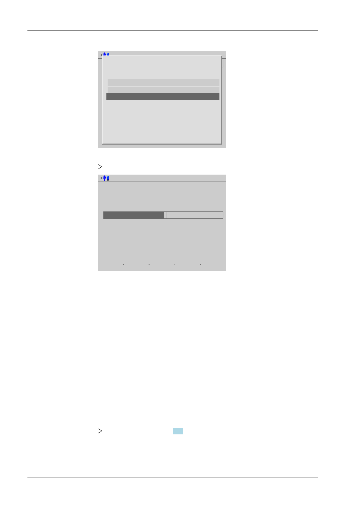
Printer @admin
Interface not assigned
Test print Save
Not assigned
Built-in RS-232
Built-in RS-485
Option-2 RS-485-A
Option-2 RS-485-B
Network printer
Network share connection
USB printer
USB folder
Printer @admin
1
2
3
Interface
Protocol
Printer type
Queue name
IP address
Network printer
LPR (Port 515)
raw
lp0
172.24.20.68
Default Test print Save
Process Controller Maxxis 5 PR 5900 4 System setup
1. Select and conrm [Network printer].
A selection window opens.
2. Select and conrm the individual parameters.
[Protocol]
Transmission protocol
Selection: consult the responsible system administrator. LPR (Port 515) or RAW (Port
9100)
[Printer type]
The printer type depends on the printer: raw, CR/LF translation, EPSON TM‑U220,
EPSON LQ-300K, Generic PCL5 (Unicode), Generic PCL5 (codepage), Generic ESC/P2
[Queue name]
The name can only be selected if [Protocol]- [LPR (Port 515)] is selected.
Selection: consult the responsible system administrator.
[IP address]
Selection: consult the responsible system administrator.
3. Press the [Test print] soft key.
A test page (see Chapter 10.2) is printed.
4. Check the printer settings and change if necessary.
5. Press the [Save] soft key to save the settings.
Minebea Intec EN-66

Printer @admin
Interface not assigned
Test print Save
Not assigned
Built-in RS-232
Built-in RS-485
Option-2 RS-485-A
Option-2 RS-485-B
Network printer
Network share connection
USB printer
USB folder
Printer @admin
Interface
Printer type
Connection name
Network share connection
CR/LF translation
Reports
Default Test print Save
4 System setup Process Controller Maxxis 5 PR 5900
4.1.4.3 Network share connection
In this menu item (under Printer), the parameters for a shared directory (network share
connection) as a printer are congured.
Accessible via MENU - [Operating]- [System setup]- [Connected devices]- [Printer][Interface]- [Network share connection] .
1. Select and conrm [Network share connection].
A selection window opens.
2. Select and conrm the individual parameters.
[Printer type]
The choice depends on the processing of the print le: raw, CR/LF translation, EPSON
TM‑U220, EPSON LQ-300K, Generic PCL5 (Unicode), Generic PCL5 (codepage),
Generic ESC/P2
[Connection name]
Save location of the print le. At least one network share connection must be
available; see Chapter 4.5.
3. Press the [Test print] soft key.
4. Check the printer settings and change if necessary.
5. Press the [Save] soft key to save the settings.
EN-67 Minebea Intec
A test page (see Chapter 10.2) is printed.

Printer @admin
Interface not assigned
Test print Save
Not assigned
Built-in RS-232
Built-in RS-485
Option-2 RS-485-A
Option-2 RS-485-B
Network printer
Network share connection
USB printer
USB folder
Printer @admin
Interface
Printer type
Selected USB printer
USB vendor
USB product
USB serial number
USB printer
raw
Zebra; LP2844 42A060400…
Zebra;
LP2844
42A060400476
Default Test print Save
Process Controller Maxxis 5 PR 5900 4 System setup
4.1.4.4 USB printer
In this menu item (under Printer), the parameters for a printer at the USB interface are
congured.
Accessible via MENU - [Operating]- [System setup]- [Connected devices]- [Printer][Interface]- [USB printer] .
1. Select and conrm [USB printer].
A selection window opens.
Inactive parameters are grayed out.
2. Select and conrm the individual parameters.
[Printer type]
The printer type depends on the printer: raw, CR/LF translation, EPSON TM-U220,
EPSON LQ-300K, Generic PCL5 (Unicode), Generic PCL5 (codepage), Generic ESC/P2
Minebea Intec EN-68
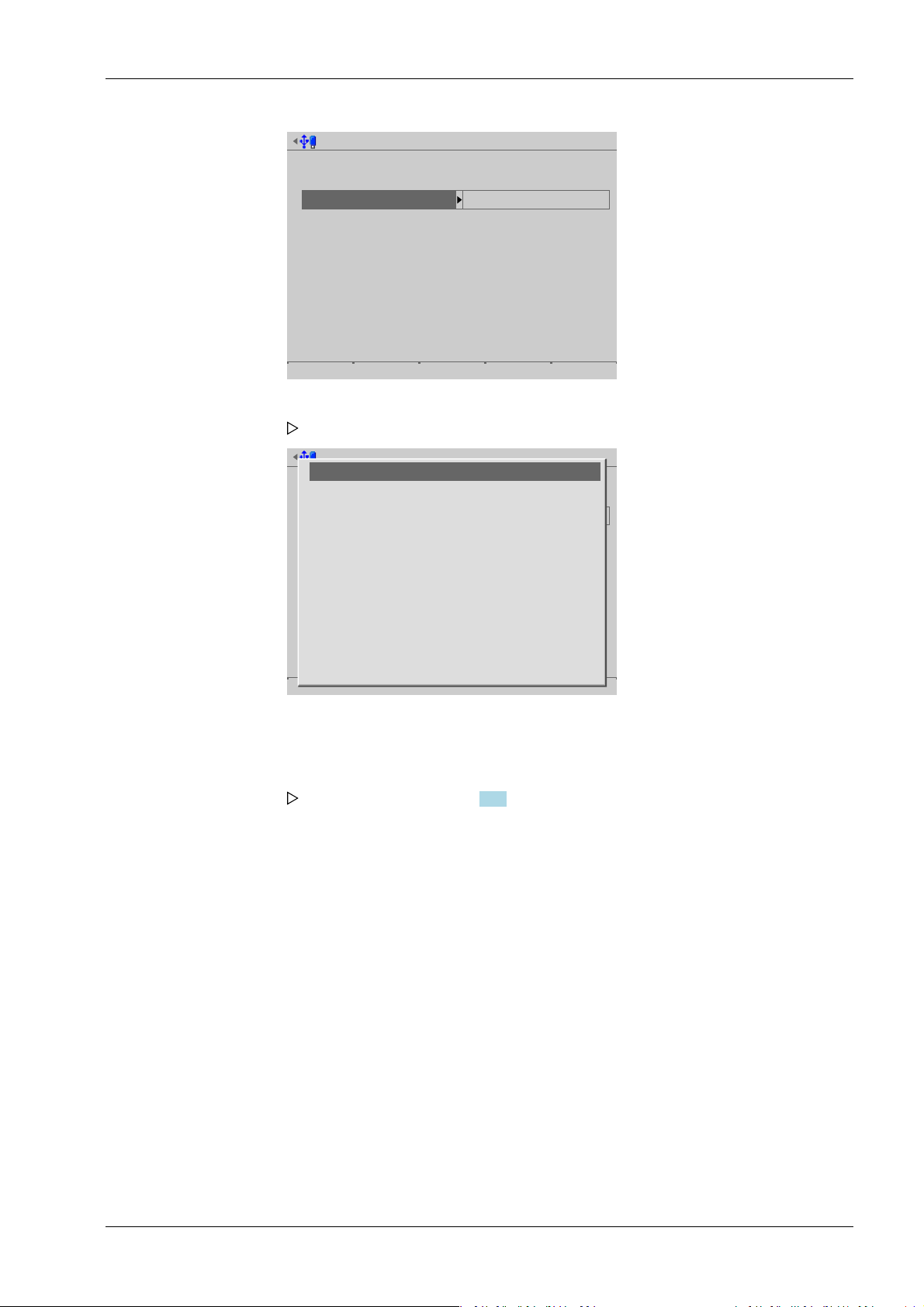
Printer 2 @admin
Interface
Printer type
Selected USB printer
USB vendor
USB product
USB serial number
USB printer
raw
Zebra; LP2844 42A060400…
Zebra;
LP2844
42A060400476
Default Test print Save
Printer 2 @admin
Interface
Printer type
Selected USB printer
USB vendor
USB product
USB serial number
USB printer
raw
Zebra; LP2844 42A060400…
Zebra;
LP2844
42A060400476
Default Test print Save
Zebra; LP2844 42A060400476
Zebra Technologies ZTC GK420d 28J110200678
4 System setup Process Controller Maxxis 5 PR 5900
3. Select and conrm [Selected USB printer].
A selection window opens.
4.1.4.5 USB folder
The connected printers (here: 2) can be selected.
4. Select and conrm the appropriate printer.
5. Press the [Test print] soft key.
A test page (see Chapter 10.2) is printed.
6. Check the printer settings and change if necessary.
7. Press the [Save] soft key to save the settings.
In this menu item (under Printer), the parameters for a folder on a connected USB stick as
a printer are congured.
Accessible via MENU - [Operating]- [System setup]- [Connected devices]- [Printer][Interface]- [USB folder] .
EN-69 Minebea Intec

Printer @admin
Interface not assigned
Test print Save
Not assigned
Built-in RS-232
Built-in RS-485
Option-2 RS-485-A
Option-2 RS-485-B
Network printer
Network share connection
USB printer
USB folder
Printer @admin
A
B
C
Interface
Printer type
Folder name
USB folder
CR/LF translation
Reports
Default Test print Save
Process Controller Maxxis 5 PR 5900 4 System setup
1. Select and conrm [USB folder].
A selection window opens.
2. Select and conrm the individual parameters.
[Printer type]
The choice depends on the processing of the print le: raw, CR/LF translation, EPSON
TM-U220, EPSON LQ-300K, Generic PCL5 (Unicode), Generic PCL5 (codepage),
Generic ESC/P2
[Folder name]
Save location of the print le (in this case: Reports).
The user-dened folder path is subject to the following restrictions:
- A maximum of 128 characters are permitted.
- 0-9, A-Z (not case-sensitive) are permitted.
- Spaces and "/" are not permitted at the start of the entry.
- Spaces, "//", "./", " /", ".." and "/ " are not permitted.
- Spaces, "." or "/" are not permitted at the end of the entry.
- "<", ">", ":", """, "/", "\", "|", "?" and "*" are not permitted.
Input: via keyboard
3. Press the [Test print] soft key.
A prompt window appears.
Minebea Intec EN-70

Printer @admin
A
B
C
Interface
Printer type
Folder name
USB folder
CR/LF translation
Reports
Default Test print Save
?
Folder does not exist on USB stick.
Create folder?
Yes No
Connected devices @admin
General devices
Remote display
ModBus-RTU master
PC via EW-Com
Printer
Remote terminal
Barcode scanner
Add. application devices
Ticket printer
Printer 2
Interface
(not assigned)
(Not assigned)
(Not assigned)
(Network printer)
(C1/CX1)
(Remote terminal TTY)
Interface
(Network printer)
(Not assigned)
Remote terminal can only
be connected via C1/CX1.
4 System setup Process Controller Maxxis 5 PR 5900
4. Press the [Yes] soft key.
A test le is created in the newly created folder.
5. Check the settings and change if necessary.
6. Press the [Save] soft key to save the settings.
4.1.5 Remote terminal
This menu item (under Connected devices) is displayed if Maxxis is equipped with C1/
CX1.
Accessible via MENU - [Operating]- [System setup]- [Connected devices]- [Remote
terminal] .
The interface used has no congurable parameters.
Note:
For further information, see PR 5900/6. and ../7. instrument manual.
4.1.6 Barcode scanner (with Ex approval)
In this menu item (under Connected devices), the parameters for a barcode scanner are
EN-71 Minebea Intec
congured.
The barcode scanner is directly connected to the remote terminal PR 5900/60 or ../70.
The scanner can only be used if option CX1 is set in Maxxis.
Accessible via MENU - [Operating]- [System setup]- [Connected devices]- [Barcode
scanner] .

Connected devices @admin
General devices
Remote display
ModBus-RTU master
PC via EW-Com
Printer
Remote terminal
Barcode scanner
Add. application devices
Ticket printer
Printer 2
Interface
(not assigned)
(Not assigned)
(Not assigned)
(Network printer)
(C1/CX1)
(Not assigned)
Interface
(Network printer)
(Not assigned)
Barcode scanner @admin
Interface not assigned
Save
Barcode scanner @admin
Interface not assigned
Save
Not assigned
Remote terminal TTY
Process Controller Maxxis 5 PR 5900 4 System setup
1. Select and conrm [Barcode scanner].
2. Select and conrm [Interface].
A selection window opens.
3. Select and conrm [Remote terminal TTY].
A selection window opens.
Minebea Intec EN-72

Barcode scanner @admin
Interface
Baudrate
Data bits
Parity
Stop bits
Remote terminal TTY
9600 baud
8 data bits
even parity
1 stop bit
Default Save
System setup @admin
Connected devices
Date & Time
Operating parameters
Network parameters
Network share connections
Fieldbus parameters
Weighing points
Display settings
License settings
User management
Alibi memory
Date & Time @admin
Time zone
Local date
Local time
Clock source
Berlin, Germany
02-08.2012
12:17:24
Local hardware clock
Default Format Save
4 System setup Process Controller Maxxis 5 PR 5900
Inactive parameters are grayed out.
4. Press the [Save] soft key to save the settings.
4.2 Date & time
In this menu item (under System setup), the parameters for the date & time are
congured.
Accessible via MENU - [Operating] - [System setup]- [Date & Time] .
1. Select and conrm [Date & Time].
EN-73 Minebea Intec
2. Select the individual parameters and conrm.
A selection window opens.

Date & Time @admin
Time zone
Local date
Local time
Clock source
Remote NTP server
Last update
online
Berlin, Germany
02-08.2012
12:11:22
Remote NTP
0.0.0.0
00.00.0000-00:00:00
Default Format Save
Process Controller Maxxis 5 PR 5900 4 System setup
[Time zone]
Selection: all existing time zones
[Local date]
Can be congured if [Clock source]- [Local hardware clock] has been selected.
Input: via keyboard
[Local time]
Can be congured if [Clock source]- [Local hardware clock] has been selected.
Input: via keyboard
[Clock source]
Selection: local hardware clock, remote NTP (Network Time Protocol)
[Remote NTP server]
The IP address can only be entered if [Clock source]- [Remote NTP] (Network Time
Protocol) has been selected.
Input: IP address via keyboard
[Last update]
Indicates when the last data was received by the remote NTP.
[online]
The checkbox ☑ indicates whether the remote NTP was successfully contacted during
the last attempt.
3. Press the [Format] soft key to set the format parameters.
A selection window opens.
Minebea Intec EN-74

Date & Time format @admin
Date format
Date of order
Date separator
Month
Year
Date/Time separator
Time format
Clock type
Time separator
ddmmyyyy
Period '.'
2 digits
4 digits
Space ' '
24 h
Colon ':'
Default Save
4 System setup Process Controller Maxxis 5 PR 5900
4. Select the individual parameters and conrm.
[Date order]
Selection: mmddyyyy, ddmmyyyy, yyyymmdd, yyyyddmm
d = day, m = month, y = year
[Date separator]
Selection: Slash /, Hyphen -, Period '.', Space, Japanese 年月日, None
[Month]
Selection: 2 digits, 3 characters
[Year]
Selection: 2 digits, 4 digits
[Date/Time separator]
Selection: Hyphen -, Space, None
[Clock type]
Selection: 12 h, 24 h
[Time separator]
Selection: Colon :, Hyphen -, Japanese , None
5. Press the [Save] soft key to save the settings.
4.3 Operating parameters
In this menu item (under System setup), the operating parameters are congured.
Accessible via MENU – [Operating] - [System setup] - [Operating parameters].
EN-75 Minebea Intec
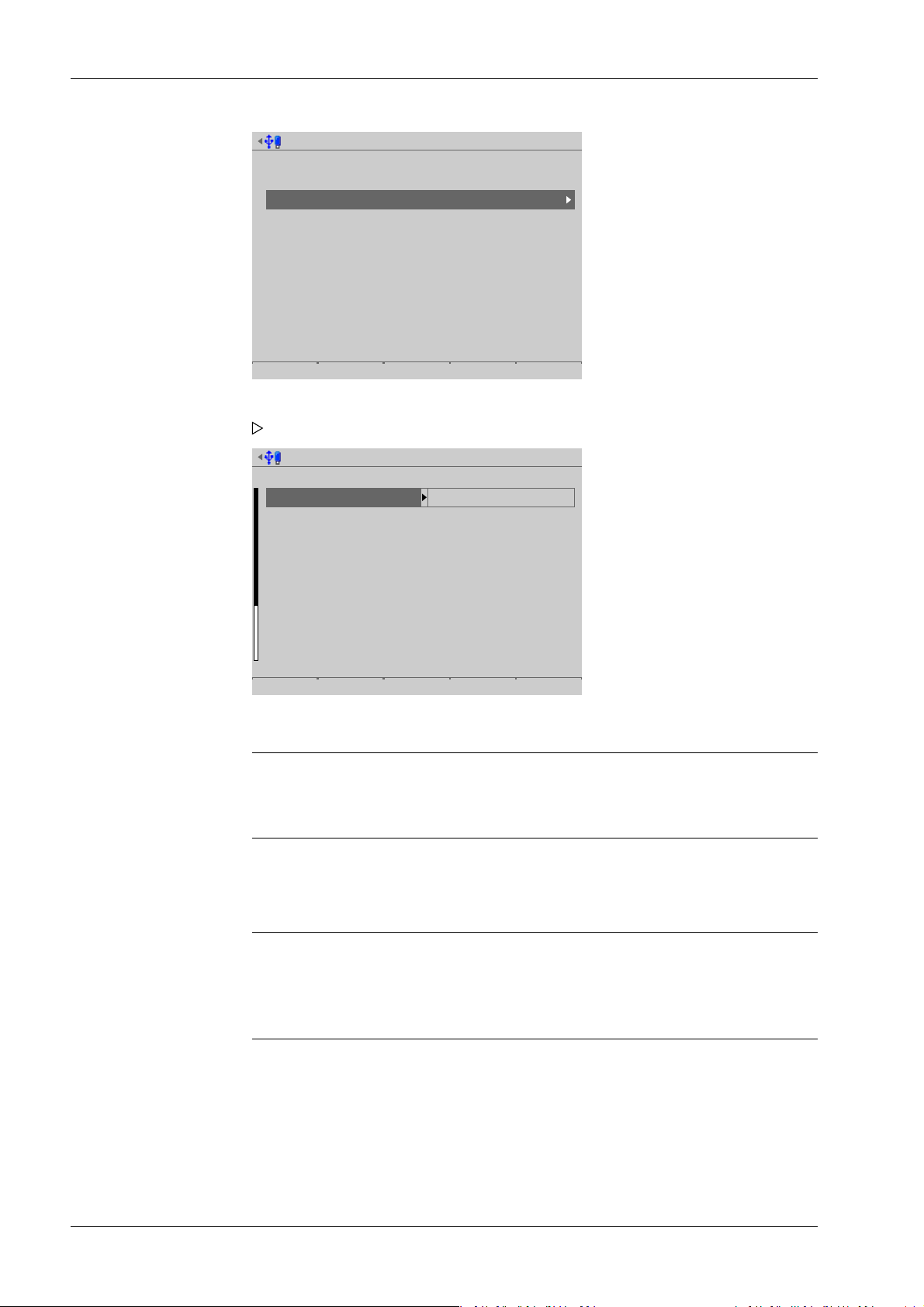
System setup @admin
Connected devices
Date & Time
Operating parameters
Network parameters
Network share connections
Fieldbus parameters
Weighing points
Display settings
License settings
User management
Alibi memory
Operating parameters @admin
Operating
Display language
External keyboard layout
Input method
Screensaver
Keyclick sound
Coldstart with STOP+EXIT
Programming
Software download
Label/Language download
Operational keys
(en) English
German QWERTZ
by language
after 10 minutes
short key click
immediatlety
disabled
Blocked
Default Input test Save
Process Controller Maxxis 5 PR 5900 4 System setup
1. Select and conrm [Operating parameters].
A selection window opens.
2. Select and conrm the individual parameters.
Note:
When user management is activated, the settings for the logged-in user remain
active.
[Display language]
Selection: (de) German, [(en) English], [(fr) French]
Note:
When user management is activated, the operating language only changes once the
currently logged-in user logs out. It is only possible to switch languages
immediately using the F1 or F2 key.
Minebea Intec EN-76
[External keyboard layout]
Selection: [English QWERTY], German QWERTZ, French AZERTY, Italian QWERTY,
Spanish QWERTY, Russian QWERTY/ицукен
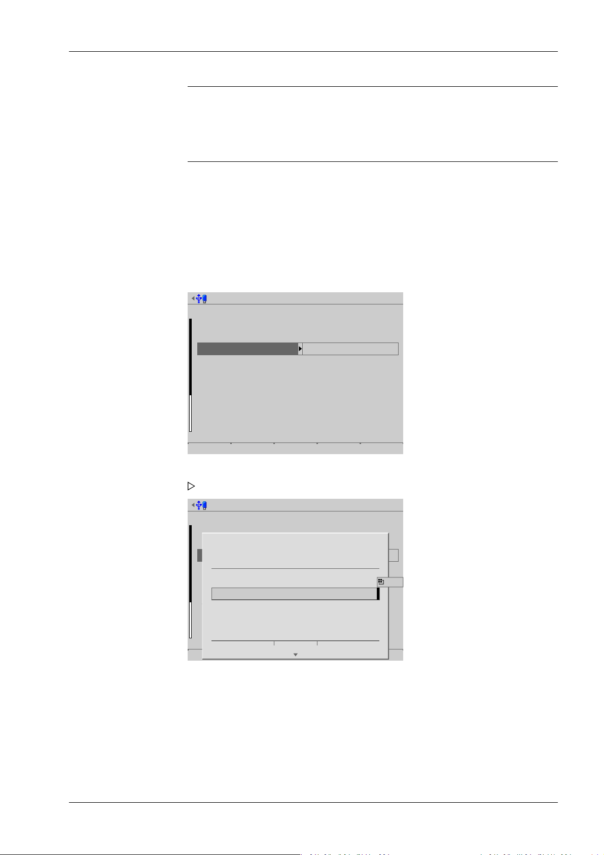
Operating parameters @admin
Operating
Display language
External keyboard layout
Input method
Screensaver
Keyclick sound
Coldstart with STOP+EXIT
Programming
Software download
Label/Language download
Operational keys
(en) English
German QWERTZ
Hepburn
after 10 minutes
short key click
immediatlety
enabled
Released
Default Input test Save
?
Enter some text for input test.
日本語の文字
Ok
IME...
4 System setup Process Controller Maxxis 5 PR 5900
Note:
This parameter applies in the case of a connected USB keyboard.
If a remote terminal is connected to Maxxis, this parameter also applies in the case
of a PS2 keyboard attached to the remote terminal.
[Input method]
This function makes it possible to enter Japanese (Hepburn) or Chinese (Pinyin)
characters even if the language in question (Japanese or Chinese) is not selected or
another language (such as English) has been selected under [Display language].
Selection: [by language], Hepburn (transliteration of Japanese "Hiragana" characters
into Latin script), Pinyin (phonetic transliteration based on the Latin alphabet)
Input test for keyboard and keypad
3. Press the [Input test] soft key to test the entry.
4. Enter the desired characters.
EN-77 Minebea Intec
An input window opens.

Process Controller Maxxis 5 PR 5900 4 System setup
During the input test using the keypad, pressing the key on the device switches between:
- in this case: Hepburn
- Numbers
- Uppercase letters
- Lowercase letters
5. Press the [OK] soft key to end the input test.
[Screensaver]
Once the screensaver is switched on, operation is only possible once a password has
been entered or a key has been pressed.
Selection: [no screensaver], after 1 minute, after 5 minutes, after 10 minutes, after 30
minutes
[Keyclick sound]
Duration of acoustic signal when keys are pressed
Selection: no key click, [short key click], medium key click, long key click
[Cold start with STOP+EXIT]
NOTICE
Data loss
A cold start leads to a loss of all data in the database.
Back the data up rst if necessary.
Selection: [disabled], immediately, 3 s
[Software download]
Load and start a new application on the device via the network.
NOTICE
Possible production downtime!
This parameter must always be set to [disabled] for production systems.
Selection: [disabled], enabled
Software can only be downloaded in running operation when [enabled] has been
selected.
[Label/Language download]
Load labels and language les onto the device via the network.
Minebea Intec EN-78

Operating parameters @admin
Operating
Keys require logged in user
Tare key
Set zero key
F1 key
F2 key
set tare & reset tare
only when not tared
no function
Change language
Default Input test Save
4 System setup Process Controller Maxxis 5 PR 5900
Note:
After a cold start, the les will be lost.
It is possible to permanently load the language les to the device using the update
software "Flashlt" from version 02.73.11 upwards.
Selection: [disabled], enabled
[Keys require logged in user]
If the checkbox ☑ is ticked, the keys with weighing point functions (e.g. set zero; F1
and F2, if congured for weighing point function) are disabled for users who are not
logged in.
[Tare key]
The function of the tare key can be congured.
Selection: disabled, [set tare & reset tare], set tare & set tare again
[Disabled] means that the key has no function.
[Set tare & reset tare] means that the device will be tared if it has not been tared
previously and the tare will be reset if the device has already been tared.
[Set tare & set tare again] means that each time a key is pressed, the instant value in
the tare memory is applied and the net display switches to 0.
[Set zero key]
The function of the set zero key can be congured.
Selection: disabled, [only when not tared], reset tare on zero set
[Disabled] means that the set zero key on the keypad has no function.
The key's function can be limited to gross mode with [only when not tared] or
switched automatically to gross mode with [reset tare on zero set].
If the set zero key with these settings has no eect, the congured zeroset range
(around the zero point set with the dead load) is already utilized due to a previous
zero-setting operation and/or automatic zero setting (see Chapter 4.7.1.1).
EN-79 Minebea Intec

Process Controller Maxxis 5 PR 5900 4 System setup
[F1 key], [F2 key]
Selection: [No function], Change language, Change user, Lock device, Toggle weight
unit, Set tare, Reset tare, Set tare & reset tare, Set tare & zero set, Analog test, Show
10x resolution
Note:
Weighing point functions are only active when the weight display is switched on.
Selection Function
No function Key has no function.
Change language Menus are immediately shown in the selected language.
Change user Login window appears on the display.
Lock device This function is only available when user management is
activated.
Toggle weight unit Toggle between the display units (see Chapter 4.7.1.3).
Set tare Current gross weight is saved in the tare memory.
Reset tare Switch to gross mode.
Set tare & reset tare The device will be tared if it has not been tared previously
Set tare & zero set The device will be tared if it has not been tared previously
Analog test The selected analog weighing point is tested only when
Show 10x resolution The weight value is briey displayed with 10x resolution.
6. Press the [Save] soft key to save the settings.
4.4 Network parameters
In this menu item (under System setup), the network parameters are congured.
Accessible via MENU - [Operating]- [System setup]- [Network parameters] .
This function is only possible if at least two units have been selected.
and the tare will be reset if the device has already been tared.
and the display will be set to 0.
the current weight is displayed.
Minebea Intec EN-80

System setup @admin
Connected devices
Date & Time
Operating parameters
Network parameters
Network share connections
Fieldbus parameters
Weighing points
Display settings
License settings
User management
Alibi memory
Network parameters @admin
A
B
C
HW address
Host name
use DHCP
IP address
Subnet mask
Default gateway
Remote access
Web server enabled
VNC access enabled
VNC client
VNC password
00:90:6C:27:FF:07
PR5900-27FF07
172.24.20.111
255.255.240.0
172.24.16.1
255.255.255.255
********
Default Save
4 System setup Process Controller Maxxis 5 PR 5900
1. Select and conrm [Network parameters].
A selection window opens.
Inactive parameters are grayed out.
2. Select the individual parameters and conrm.
[HW address]
Fixed address determined by the device.
[Host name]
The host name must be unique in the network!
Always follow the IT security guidelines.
The user-dened device name is subject to the following restrictions:
- Minimum number of characters: 2, maximum number of characters: 24.
EN-81 Minebea Intec
- The rst character must be a letter. Spaces are not permitted.
- 0-9, A-Z (not case-sensitive) are permitted.
- – or . may be included, but neither at the end nor in succession.
Input: via keyboard
NOTICE
Use unique host names.

Network parameters @admin
HW address
Host name
use DHCP
IP address
Subnet mask
Default gateway
Remote access
Web server enabled
VNC access enabled
VNC client
VNC password
00:90:6C:27:FF:07
PR5900-27FF07
172.24.20.111
255.255.240.0
172.24.16.1
255.255.255.255
********
Default Save
Process Controller Maxxis 5 PR 5900 4 System setup
[use DHCP]
If ☑ is checked (default setting: DHCP selected), the server automatically allocates the
IP address, subnet mask, and default gateway.
If no checkbox ☐ is ticked, the settings for the [IP address], [Subnet mask] and
[Default gateway]must be dened in conjunction with the responsible system
administrator.
[Web server enabled]
If the checkbox ☑ is ticked, the device website can be used.
[VNC access enabled]
If the checkbox ☑ is ticked, the device can be operated via VNC.
[VNC client]
This address can be used to allow access to the interface.
Address Access
172.24.21.101 only from client machine with this address.
172.24.21.255 from any client with address within range
172.24.21.1…172.24.21.254.
255.255.255.255 from a client with any address
[VNC password]
If a password is entered (max. 8 characters), this password must be entered in the
VNC client to access the interface.
[Default] soft key
- resets the host name to PR5900-XXXXXX, where XXXXXX stands for the last
3 bytes of the hardware address (MAC ID).
- sets [use DHCP] to active.
Minebea Intec EN-82
- sets the IP address to 0.0.0.0.
- sets the subnet mask to 0.0.0.0.
- sets the default gateway to 0.0.0.0.
- sets the VNC client to 255.255.255.255.

System setup @admin
Connected devices
Date & Time
Operating parameters
Network parameters
Network share connections
Fieldbus parameters
Weighing points
Display settings
License settings
User management
Alibi memory
4 System setup Process Controller Maxxis 5 PR 5900
- resets the VNC password to [no password].
Note:
Blackbox device: DHCP is deactivated and the xed IP address 192.168.1.2 is set;
see also Chapter 2.8.2.
3. Press the [Save] soft key to save the settings.
4.5 Network share connections
In this menu item (under System setup), the parameters for shared directories (network
share connections) are congured and made available for system maintenance (e.g.
storing/saving data on the network).
- [Add], see Chapter 4.5.1.
- [Change], see Chapter 4.5.2.
- [Remove], see Chapter 4.5.3.
The following order must be observed without exception:
- One or more directories on the server/notebook/PC must be shared; see the manual
for the operating system in question (e.g., Windows 7: click the directory, right-click
on [Advanced Sharing…] and activate [Share this folder]. Then click [OK].)
- In the menu [Operating]- [System setup]- [Network share connections] , congure
the connections to the shared directories on the server/notebook/PC.
Accessible via MENU - [Operating]- [System setup]- [Network share connections] .
Select and conrm [Network share connections].
The window listing the available network share connections opens.
EN-83 Minebea Intec

Configure network share connections @admin
No connections configured
Add Change Remove
Create network share connection @admin
A
B
C
Connection name
Server
Share name on server
Folder path
Domain
User name
Password ***********************************...
Test Save
Configure network share connections @admin
No connections configured
Add Change Remove
Process Controller Maxxis 5 PR 5900 4 System setup
4.5.1 Add
In this menu item (under Network share connections), the parameters for shared
directories (network share connections) are congured and added.
Accessible via MENU - [Operating]- [System setup]- [Network share conditions]- [Add] .
The list is empty because no connections have been congured yet.
1. Press the [Add] soft key.
A selection window opens.
2. Select the individual parameters and conrm.
[Connection name]
The name must be unique.
Minebea Intec EN-84

Edit network share connection @admin
A
B
C
Connection name
Server
Share name on server
Folder path
Domain
User name
Password
Report
XXX.company.com
Office
Prod_data/Share_PR5900/R...
COMPANY
forename.surname
*********************************...
Test Save
i
Test passed
Ok
4 System setup Process Controller Maxxis 5 PR 5900
Input: max. 16 alphanumeric characters
[Server]
The host name (see Chapter 4.4) or the IP address may be entered.
[Share name on server]
The existing name on the server where the directory was created.
Input: max. 64 characters
[Folder path]
The existing folder path within network sharing (only if required).
The user-dened folder path is subject to the following restrictions:
- A maximum of 128 characters are permitted.
- 0-9, A-Z (not case-sensitive) are permitted.
- Spaces and "/" are not permitted at the start of the entry.
- Spaces, "//", "./", " /", ".." and "/ " are not permitted.
- Spaces, "." or "/" are not permitted at the end of the entry.
- "<", ">", ":", """, "/", "\", "|", "?" and "*" are not permitted.
Input: via keyboard
[Domain]
The existing range for network sharing (only if required).
Input: max. 64 characters
[User name]
User name in the network (only if required).
Input: max. 64 characters
[Password]
Password in the network (only if required).
Input: max. 64 characters
3. Press the [Test] soft key to test the connection.
An information window is displayed.
EN-85 Minebea Intec
4. Press the [OK] soft key to hide the window.

Configure network share connections @admin
Report
Add Change Remove
Edit network share connection @admin
A
B
C
Connection name
Server
Share name on server
Folder path
Domain
User name
Password
Report
XXX.company.com
Office
Prod_data/Share_PR5900/R...
COMPANY
forename.surname
*********************************...
Test Save
Configure network share connections @admin
Report
Add Change Remove
Process Controller Maxxis 5 PR 5900 4 System setup
If an error message appears, the conguration must be changed.
5. Press the [Save] soft key to save the settings.
The newly congured connection (here: Report) is displayed.
4.5.2 Change
In this menu item (under Network share connections), the parameters for congured
shared directories (network share connections) are modied.
Accessible via MENU - [Operating]- [System setup]- [Network share conditions][Change] .
1. Select the desired connection.
2. Press the [Change] soft key.
A selection window opens.
Minebea Intec EN-86
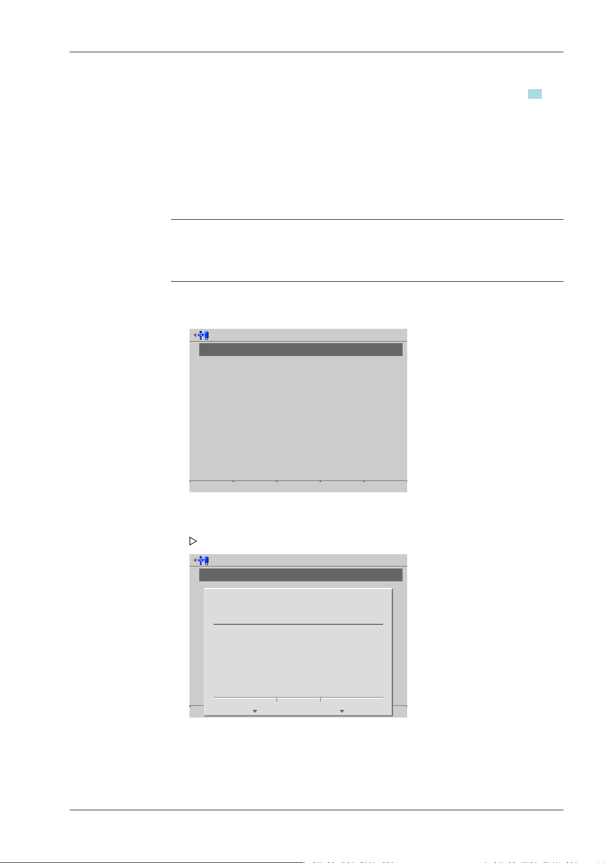
Configure network share connections @admin
Report
Add Change Remove
Configure network share connections @admin
Report
Add Change Remove
?
Delete network share connection report?
Yes No
4 System setup Process Controller Maxxis 5 PR 5900
3. Select the individual parameters, conrm and modify if required, see Chapter 4.5.
4. Press the [Test] soft key to test the connection.
5. Change the conguration again if necessary.
6. Press the [Save] soft key to save the settings.
4.5.3 Remove
In this menu item (under Network share connections), the parameters for congured
shared directories (network share connections) are removed/deleted.
Note:
Only the settings in the device are deleted.
No network share les are deleted.
Accessible via MENU – [Operating] - [System setup] - [Network share connections] [Remove].
1. Select the desired connection.
2. Press the [Remove] soft key
3. Press the corresponding soft key.
A prompt window opens.
EN-87 Minebea Intec

System setup @admin
Connected devices
Date & Time
Operating parameters
Network parameters
Network share connections
Fieldbus parameters
Weighing points
Display settings
License settings
User management
Alibi memory
Fieldbus parameters @admin
fieldbus protocol
I/Os
Fieldbus mode
Scale interface
IP address
Subnet mask
ProfiNet
8 byte I/O
Scale interface
WP A
192.168.1.1
255.255.255.0
Default Save
Process Controller Maxxis 5 PR 5900 4 System setup
4.6 Fieldbus parameters
In this menu item (under System setup), the parameters for the eldbus card used are
congured.
This menu item can only be selected if a eldbus card has been installed in Option FB.
Depending on the eldbus card used, the corresponding eldbus protocol appears
automatically:
- [Probus‑DP] for PR 1721/51
- [DeviceNet] for PR 1721/54
- [ProNet I/O] for PR 1721/56 and PR 1721/76
- [EtherNet IP] for PR 1721/57 and PR 1721/77
Note:
The protocol for the scale interface is described in Chapter 8.2.
The protocol for the SPM interface is described in Chapter 8.3.
Accessible via MENU – [Operating] - [System setup] - [Fieldbus parameters].
1. Select and conrm [Fieldbus parameters].
A selection window opens.
Minebea Intec EN-88
2. Select and conrm the individual parameters.
The parameters are dependent on the relevant eldbus (here: ProNet).

4 System setup Process Controller Maxxis 5 PR 5900
[I/Os]
Selection: 8 to 256 Byte I/O
[Fieldbus operating mode]
Selection: Only application, scale interface, SPM interface
[Only application] is selected for project applications.
[Scale interface] is selected if scale and application values are exchanged via the
eldbus interface.
[SPM interface] is selected if the SPM needs to be accessed via the eldbus interface.
[Scale interface]
Selection: disabled; WP A (equals 8 bytes); WP A, B (equals 16 bytes); WP A, B, C
(equals 24 bytes); WP A, B, C, D (equals 32 bytes)
Network-based eld bus protocols:
[IP address]
Input: via keyboard
[Subnet mask]
Input: via keyboard
Probus-DP:
[Probus-DP address]
Input: via keyboard
3. Press the [Save] soft key to save the settings.
4.6.1 Fieldbus settings for the SPS
Conguration of the interface is carried out in the device under [System setup] - [Fieldbus
parameters], see Chapter 4.6.
Requirements:
- The relevant eldbus card has been installed, see PR 5900 installation manual.
- The parameters have been selected and saved according to the weighing points
(1× WP = 8 byte I/O), see Chapter 4.6.
- The corresponding device description data has been loaded to the SPS development
environment, see PR 5900 installation manual.
- ProBus-DP: xx_xx.gsd
- DeviceNet: xx_xx.eds
- ProNet I/O: GSDML-xx-xx-xx-xx.xml
- EtherNet-IP: xx_xx_xx.eds
Card test:
The eldbus cards have LEDs that display their status, see PR 5900 installation manual.
All inputs and outputs are displayed in the menu [Operating] - [System maintenance] -
[Test hardware] - [I/O cards test] - [Option FB].
EN-89 Minebea Intec

Process Controller Maxxis 5 PR 5900 4 System setup
NOTICE
Potential network problems
A unique device name must be assigned for the hardware conguration and
assignment/download.
4.7 Weighing points
In this menu item (under System setup), the corresponding weighing electronics are
assigned to a logical weighing point and congured.
- [Internal weighing point], see Chapter 4.7.1.
- [Liquid counter], see Chapter 4.7.2.
- [User scale], see Chapter 4.7.3.
- [xBPI scale], see Chapter 4.7.5.
- [SBI scale], see Chapter 4.7.6.
- [Pendeo Truck], see Chapter 4.7.7.
- [Pendeo Process], see Chapter 4.7.8.
- [PR-Net weighing point], see Chapter 4.7.9.
- [Mettler-Scale], see Chapter 4.7.10.
- [SMA scale], see Chapter 4.7.11.
The device can manage up to four weighing points (scales). The number of scales to be
used is determined by the application package. There are physical weighing electronics/
scales (e.g. [internal], [xBPI scale]) and logical weighing points (WP A, WP B, WP C, and
WP D).
A totalization of two scales can only take place on C = A+B.
Restrictions when selecting scale protocols:
- A maximum of three digital scale protocols (excluding SBI) are possible at the same
time:
- xBPI
- Pendeo
- A maximum of two digital scale protocols are possible if [Operating] - [System setup]
- [Connected devices] - [ModBus-RTU master] has been selected in the menu.
The physical weighing point can be assigned to a logical weighing point in the menu
[Operating] - [System setup] - [Weighing points] in accordance with the following table:
Weighing electronics Logical weighing point
WP‑‑A WP‑‑B WP‑‑C WP‑‑D
[not assigned] W W W W
[Internal weighing point] W W - [A+B] - - W [Liquid counter] W W W W
Minebea Intec EN-90
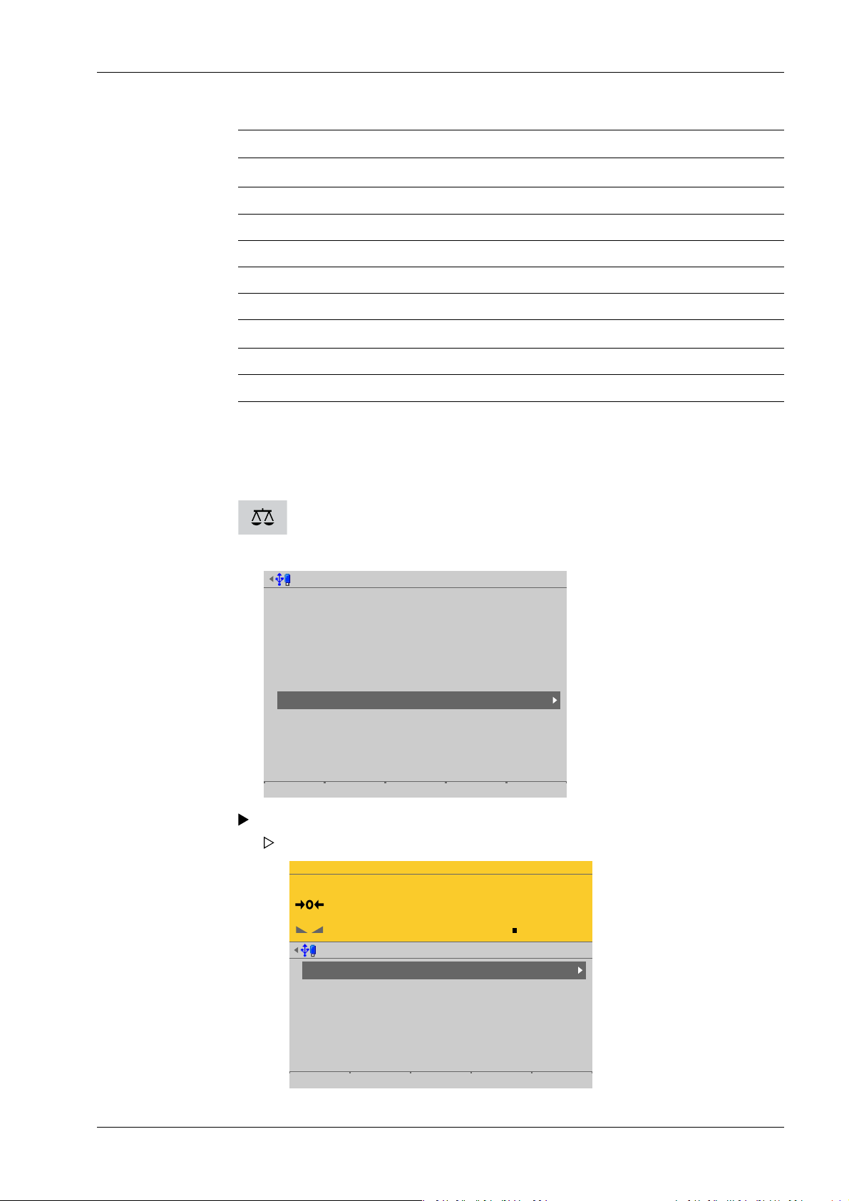
System setup @admin
Connected devices
Date & Time
Operating parameters
Network parameters
Network share connections
Fieldbus parameters
Weighing points
Display settings
License settings
User management
Alibi memory
WP-A
Max 3000g d= 0.1g
00
g
Weighing points @admin
Weighing point A
Weighing point B
Weighing point C
Weighing point D
Internal weighing point
Pendeo Truck
xBPI scale
User scale
Parameters Calib Units
4 System setup Process Controller Maxxis 5 PR 5900
Weighing electronics Logical weighing point
WP‑‑A WP‑‑B WP‑‑C WP‑‑D
[User scale] W W W W
[xBPI scale] W W W W
[SBI scale] W W W W
[Pendeo Truck] W W W W
[Pendeo Process] W W W W
[PR‑Net weighing point]
W W W W
[Mettler-Scale] W W W W
[SMA scale] W W W W
When the PR 5900 internal weighing electronics are plugged into the slots for A or B, they
are automatically assigned to weighing point A or B, respectively.
Weighing electronics can only be assigned to a logical weighing point once.
WP‑A is displayed as the factory setting.
This key can be used to switch the display to the desired weighing point.
Accessible via MENU – [Operating] - [System setup] - [Weighing points].
EN-91 Minebea Intec
Select and conrm [Weighing points].
The Weighing points menu appears.

Weighing point A @admin
Weighing point not assigned
Save
Weighing point A @admin
Weighing point not assigned
Save
Not assigned
Internal weighing point
Liquid counter
User scale
xBPI scale
SBI scale
Pendeo Truck
Pendeo Process
PR-Net weighing point
Mettler-Scale
SMA scale
Process Controller Maxxis 5 PR 5900 4 System setup
4.7.1 Internal weighing point
In this menu item (under Weighing points), the weighing electronics of an internal
weighing point are assigned to a logical weighing point and congured.
- [Parameters] (weighing electronics), see Chapter 4.7.1.1.
- [Calib], see Chapter 4.7.1.2.
- [New], see Chapter 4.7.1.2.1.
- [Modify] (for small changes only), see Chapter 4.7.1.2.2.
- [Units] (display units and display accuracy), see Chapter 4.7.1.3.
Accessible via MENU – [Operating] - [System setup] - [Weighing points] - [Weighing
point x] - [Weighing point] - [Internal weighing point].
1. Conrm [Weighing point].
A selection window opens.
2. Select and conrm [Internal weighing point].
3. Press the [Save] soft key to save the settings.
The weighing electronics are now assigned to the weighing point.
Minebea Intec EN-92

WP-A
Max 3000g d= 0.1g
00
g
Weighing points @admin
Weighing point A
Weighing point B
Weighing point C
Weighing point D
Internal weighing point
Pendeo Truck
xBPI scale
User scale
Parameters Calib Units
WP-A
Max 3000g d= 0.1g
00
g
Weighing points @admin
Weighing point A
Weighing point B
Weighing point C
Weighing point D
Internal weighing point
Pendeo Truck
xBPI scale
User scale
Parameters Calib Units
4 System setup Process Controller Maxxis 5 PR 5900
4.7.1.1 Parameters
In this menu item, the parameters for the Internal weighing point weighing electronics
are congured.
For detailed descriptions of the following parameters:
- [W&M] (legal metrology), see Chapter 4.7.1.1.1.
- [Range mode] (range selection for scales), multi-range, see Chapter 4.7.1.1.2 and
multi-interval scale, see Chapter 4.7.1.1.3
Accessible via MENU - [Operating] - [System setup] - [Weighing points] - [Weighing
point x] - [Parameters] .
1. In this case: Select [Weighing point A] with [Internal weighing point] and press the
[Parameters] soft key.
A selection window opens.
EN-93 Minebea Intec

WP-A
Max 3000g d= 0.1g
00
–
g
Weighing points @admin
Settings locked
W&M
Measurement time
Digital filter
Cutoff frequency
External load cell supply
none
160 ms
aperiodic
2.00 Hz
below or equal 8 V
Default Save
Process Controller Maxxis 5 PR 5900 4 System setup
2. Select and conrm the individual parameters.
[Settings locked]
The weighing point settings and assignment can only be viewed as if the
corresponding CAL switch were closed; see Chapter 2.7.1.
[W&M]
Setting for operation in legal metrology.
Selection: [None], OIML, NTEP (for USA) or NSC (for Australia)
For description and settings, refer to Chapter 4.7.1.1.1
[Measurement time]
The duration of a measurement can be selected.
Selection: 5 ms, 10 ms, 20 ms, 40 ms, 80 ms, 160 ms, 320 ms, 640 ms, 960 ms,
1280 ms, 1600 ms, [≤1 s]
A measurement time of ≤1 s must be selected for use in legal metrology.
[Digital lter]
The following includes examples of interference signals for the dierent lter types:
- Bessel lter
Minebea Intec EN-94

4 System setup Process Controller Maxxis 5 PR 5900
- Aperiodic lter
- Butterworth lter
- Tschebysche lter
A digital lter can be switched on only with the measurement time set to ≤160 ms
Selection: no lter, Bessel, aperiodic, Butterworth, Tschebysche.
If no particularly frequent uctuations are expected in ongoing operation, the
following settings are recommended:
- [Measurement time]: ≤160 ms
- [Digital lter]: aperiodic
- [Cuto frequency]: 2.00 Hz
EN-95 Minebea Intec

WP-A
Max 3000g d= 0.1g
00
+
g
Weighing points @admin
1
2
3
Standstill time
Standstill range
Tare timeout
Zeroset range
Zerotrack
Zerotrack range
0.50 s
1.0 d
25 s
50.00 d
Yes
0.25 d
Default Save
Process Controller Maxxis 5 PR 5900 4 System setup
[Cuto frequency]
The smaller the cuto frequency, the slower the measurement and the more stable
the measurement result.
The cuto frequency for the low pass lter can be selected. The permitted range is:
0.01…40.00 Hz.
The available options depend on the measurement time.
The menu line [Cuto frequency] only appears if the digital lter is switched on.
[External load cell supply]
The external supply voltage is selected.
Selection: below or equal 8 V, above 8 V
[Standstill time]
The parameters [Standstill time] and [Standstill range] are used to dene the
standstill of the scale (stable balance).
The [Standstill time] parameter is entered in seconds. The permitted range is:
0.00…2 s.
The time can be entered from 0.00 to 2.00 seconds, but always makes up at least one
measurement time.
[Standstill range]
As long as the weight uctuations remain within this range, the device is determined
to be stable.
The [Standstill range] parameter is entered in "d". The permitted range is:
0.01…10.00 d.
For use in legal metrology, ≤1 d must be selected.
[Tare timeout]
Timeout for a tare/zeroset command that cannot be executed (e.g. due to mechanical
instability of the scale, incorrect lter setting, resolution too high, standstill condition
too strict).
This parameter is given in seconds. The permitted range is: 0.0…[2.5]…25 s.
At 0.0 s taring is only carried out when the scale is already stable.
Minebea Intec EN-96

WP-A
Max 3000g d= 0.1g
00
+
g
Weighing points @admin
1
2
3
Zerotrack step
Zerotrack time
Overload
Minimum weight
Range mode
0.25 d
1.0 s
9 d
20 d
single range
Default Save
4 System setup Process Controller Maxxis 5 PR 5900
[Zeroset range]
Determine a ±range around the zero point determined by the dead load during
calibration; within this range
- the displayed gross weight can be set to zero by pressing the zero-setting key (or
by a corresponding external command), and
- automatic zero tracking is active.
Setting range: 0.00…10000.00 d
For use in legal metrology a value ≤2% of the max must be entered, example: 60 d for
3000 e of Class III.
[Zerotrack]
The zero display is automatically maintained within set limits.
Selection: No/Yes
When [No] is selected, the next three parameters are not shown.
When [Yes] is selected, values for the next three parameters must be entered.
[Zerotrack range]
Range within which automatic zerotrack compensates for deviations.
Setting range: 0.25…10000.00 d
For use in legal metrology a value of 0.25 d must be entered.
[Zerotrack step]
If a weight change exceeds the adjusted value, automatic tracking does not function
any more.
EN-97 Minebea Intec
Setting range for automatic tracking increments: 0.25…10 d
For use in legal metrology a value of 0.25 d must be entered.
[Zerotrack time]
Time interval for automatic zerotrack.
Setting range: 0.1…25 s
For use in legal metrology a value of 1 s must be entered.
[Overload]
Weighing range above the maximum capacity (Max) without error message.

Process Controller Maxxis 5 PR 5900 4 System setup
Setting range: 0…9999999 d
For use in legal metrology a value of max. 9 d = e must be set.
[Min. weight]
Minimum weight at which a print command can be triggered.
Setting range: 0…9999999 d
For use in legal metrology a value of at least 20 d must be set.
[Range mode]
Selection: single range, multi-range, multi-interval
For range selection for scales and settings, refer to Chapter 4.7.1.1.2 and 4.7.1.1.3
[Default] soft key
Settings are reset to factory settings.
3. Press the [Save] soft key to save the settings.
4.7.1.1.1 W&M (use in legal metrology)
In this menu item (under Parameters), the parameters of the Internal weighing point
weighing electronics are congured for use in legal metrology.
Accessible via MENU - [Operating] - [System setup] - [Weighing points] - [Weighing
point x] - [Parameters] - [W&M] .
The following parameters can be selected: [None], OIML, NTEP (for USA) or NSC (for
Australia)
[None] [OIML] [NTEP] [NSC]
Gross weight display B B G G
Recommended
min. measurement signals
If legal-for-trade mode is switched on, the parameter settings (zerotrack etc.) must be
selected accordingly. The device does not perform a check of this.
A unique check number is created every time a calibration or changed parameters are
saved. This can be viewed in the menu [Operating] - [System information] - [Show
calibration check numbers] (see Chapter 5.7) and may also be written on the W&M label.
See also Chapter 4.7.1.2.
0.2 mV/V @
30,000 d
0.4 mV/V @
60,000 d
0.2 mV/V @
3000 e
0.4 mV/V @
6000 e
0.2 mV/V @
3000 e
0.4 mV/V @
6000 e
0.2 mV/V @
3000 e
0.4 mV/V @
6000 e
4.7.1.1.2 Range mode: Multi-range
In this menu item (under Parameters), a multi-range scale (of Class III or single-range
scale of Class I and II with variable scale interval) of the Internal weighing point weighing
electronics is congured
The multi-range scale is a scale with two or more weighing ranges with dierent
maximum capacities and scale intervals. There is only one load receptor, with each range
covering zero to its maximum capacity.
When [Range mode] = [Multi-range], the scale has up to three ranges with dierent
resolution.
Minebea Intec EN-98
 Loading...