

Minebea Intec PR 5410 Instrument Manual

Instrument Manual
X3 Process Indicator PR 5410
Translation of the original instrument manual 9499 050 54103 Edition 11.1.0 10/23/2017
Release 4.50
Minebea Intec GmbH, Meiendorfer Str. 205 A, 22145 Hamburg, Germany
Phone: +49.40.67960.303 Fax: +49.40.67960.383

Foreword
Must be followed!
Any information in this document is subject to change without notice and does not represent a commitment on
the part of Minebea Intec unless legally prescribed. This product should be operated/installed only by trained
and qualied personnel. In correspondence concerning this product, the type, name, and release number/serial
number as well as all license numbers relating to the product have to be cited.
Note
The product is partially protected by copyright. It may not be changed or copied, and it may not be used without
purchasing or written permission from the copyright owner (Minebea Intec). Its use constitutes acceptance by
you of the above-mentioned provisions.

X3 Process Indicator PR 5410 Table of contents
Table of contents
1 Introduction......................................................................................................................................... 9
1.1 Read the manual.........................................................................................................................................................9
1.2 This is what instructions look like.............................................................................................................................9
1.3 This is what lists look like........................................................................................................................................... 9
1.4 This is what menus and soft keys look like.............................................................................................................9
1.5 This is what safety instructions look like................................................................................................................. 9
1.6 Hotline........................................................................................................................................................................ 10
2 Safety instructions.............................................................................................................................. 11
2.1 General notes .............................................................................................................................................................11
2.2 Intended use............................................................................................................................................................... 11
2.3 Incoming goods inspection...................................................................................................................................... 11
2.4 Before operational startup....................................................................................................................................... 11
2.4.1 Installation ....................................................................................................................................................... 11
2.4.2 Opening the device.........................................................................................................................................12
2.4.3 Supply voltage connection............................................................................................................................12
2.4.4 Protective conductor connection.................................................................................................................13
2.5 RF interference suppression....................................................................................................................................13
2.6 Failure and excessive stress.....................................................................................................................................13
2.7 Important note.......................................................................................................................................................... 14
2.8 Repairs and maintenance........................................................................................................................................ 14
2.8.1 General information ...................................................................................................................................... 14
2.8.2 Electrostatically sensitive parts ................................................................................................................... 14
2.8.3 Replacing fuses .............................................................................................................................................. 14
3 Device description ..............................................................................................................................15
3.1 General information..................................................................................................................................................15
3.2 Overview of the device .............................................................................................................................................15
3.2.1 Communication protocols............................................................................................................................ 16
3.3 Housing ...................................................................................................................................................................... 16
3.3.1 General information...................................................................................................................................... 16
3.3.2 Dimensions ......................................................................................................................................................17
3.3.3 Control panel cut-out.....................................................................................................................................17
3.4 Display and control panel.........................................................................................................................................17
3.4.1 General information .......................................................................................................................................17
3.4.2 Overview.......................................................................................................................................................... 18
3.4.3 Display ............................................................................................................................................................. 18
3.4.4 Operating elements........................................................................................................................................21
3.5 Overview of connections.........................................................................................................................................28
3.5.1 Plug-in cards...................................................................................................................................................29
EN-1 Minebea Intec

X3 Process Indicator PR 5410 Table of contents
4 Device installation...............................................................................................................................31
4.1 General information..................................................................................................................................................31
4.2 Mechanical preparation............................................................................................................................................31
4.2.1 Mechanical preparation .................................................................................................................................31
4.3 EMC-compliant installation ....................................................................................................................................32
4.3.1 Connecting the screens................................................................................................................................. 32
4.3.2 Connecting the equipotential bonding conductor................................................................................... 32
4.4 Hardware construction ............................................................................................................................................32
4.4.1 Main board......................................................................................................................................................32
4.4.2 Display board..................................................................................................................................................34
4.4.3 Network port...................................................................................................................................................34
4.4.4 RS-232 interface.............................................................................................................................................34
4.4.5 Digital inputs ..................................................................................................................................................39
4.4.6 Digital outputs................................................................................................................................................ 41
4.5 Connecting analog load cells and platforms........................................................................................................45
4.5.1 General information ......................................................................................................................................45
4.5.2 Connecting a load cell with a 4-wire cable.................................................................................................45
4.5.3 Connecting a load cell with a 6-wire cable.................................................................................................47
4.5.4 Connecting between 2 and8 load cells (650 Ω) using a 6-wire connection cable ..............................48
4.5.5 Connecting load cells of type series PR 6221 ............................................................................................48
4.5.6 Testing the measuring circuit ......................................................................................................................49
4.5.7 External supply to load cells.........................................................................................................................49
4.5.8 Connecting to input/output interface PR 1626/60 ..................................................................................50
4.5.9 Connecting an analog weighing platform (CAP… series).........................................................................52
4.6 Accessories ................................................................................................................................................................54
4.6.1 General information ......................................................................................................................................54
4.6.2 2× RS-232-interface ...................................................................................................................................... 57
4.6.3 1× RS-232 interface and 1× RS-485 interface ............................................................................................59
4.6.4 Analog inputs and outputs........................................................................................................................... 72
4.6.5 BCD output (open emitter) ...........................................................................................................................76
4.6.6 BCD output (open collector)........................................................................................................................ 80
4.6.7 Switch settings ...............................................................................................................................................84
4.6.8 Output modes ................................................................................................................................................84
4.6.9 Opto-decoupled inputs and outputs..........................................................................................................86
4.6.10 Status LEDs on eldbus card........................................................................................................................93
4.6.11 ProBus-DP interface ...................................................................................................................................94
4.6.12 InterBus-S interface.......................................................................................................................................99
4.6.13 DeviceNet interface .....................................................................................................................................104
4.6.14 CC-Link interface .........................................................................................................................................108
4.6.15 ProNet I/O interface...................................................................................................................................110
4.6.16 EtherNet IP interface ....................................................................................................................................113
5 "Standard" application .....................................................................................................................116
Minebea Intec EN-2

X3 Process Indicator PR 5410 Table of contents
5.1 Functions...................................................................................................................................................................116
5.1.1 General information .....................................................................................................................................116
5.1.2 Display functions...........................................................................................................................................116
6 "EasyFill" application ........................................................................................................................ 117
6.1 Functions................................................................................................................................................................... 117
6.1.1 General information ..................................................................................................................................... 117
6.1.2 Display functions........................................................................................................................................... 117
6.1.3 Filling mode ................................................................................................................................................... 117
6.2 Application menu [Start] ........................................................................................................................................ 117
7 Commissioning.................................................................................................................................. 119
7.1 Power failure/Data backup/Restart .....................................................................................................................119
7.1.1 Power failure..................................................................................................................................................119
7.1.2 Data backup...................................................................................................................................................119
7.1.3 Overwrite protection....................................................................................................................................119
7.1.4 Restart ............................................................................................................................................................ 121
7.2 Switching on the device..........................................................................................................................................121
7.2.1 Setting the date and time........................................................................................................................... 122
7.3 Switching o the device ........................................................................................................................................ 123
7.4 Warm-up time......................................................................................................................................................... 123
7.5 Conguring and calibrating using the front-panel keys.................................................................................. 123
7.5.1 Parameter table (SEtuP).............................................................................................................................. 123
7.5.2 Recalibrating the internal weighing point using the front-panel keys ............................................... 127
7.5.3 Changing the dead load of the internal weighing point using the front-panel keys........................ 130
7.5.4 Displaying the calibration data of the internal WP using the front-panel keys.................................. 131
7.5.5 Reading out calibration data for WP dead load and max using the front-panel keys...................... 133
7.5.6 Search for Pendeo load cells and set dead load using the front-panel keys ..................................... 134
7.5.7 Creating a PIN code using the front-panel keys .....................................................................................135
7.5.8 Deleting the PIN code using the front-panel keys ..................................................................................137
7.5.9 Entering eldbus parameters using the front-panel keys .....................................................................137
7.5.10 Entering the network address using the front-panel keys.................................................................... 139
7.5.11 Displaying the network address using the front-panel keys................................................................ 142
7.6 Displaying/deleting alibi entries using the front-panel keys.......................................................................... 142
7.6.1 Displaying/deleting alibi entries ............................................................................................................... 143
7.6.2 Deleting alibi entries.................................................................................................................................... 144
7.7 Finding and connecting a device with a notebook/PC .....................................................................................144
7.8 Finding and connecting the device automatically in the network.................................................................. 145
7.9 Searching the device in the network with "IndicatorBrowser"........................................................................ 145
7.10 Resetting the network address ............................................................................................................................146
7.11 Operation using VNC ............................................................................................................................................. 147
7.12 Operation via a web browser................................................................................................................................148
7.13 System setup........................................................................................................................................................... 149
EN-3 Minebea Intec

X3 Process Indicator PR 5410 Table of contents
7.13.1 Serial ports parameter ................................................................................................................................ 149
7.13.2 Date & time ...................................................................................................................................................149
7.13.3 Operating parameter .................................................................................................................................. 149
7.13.4 Printing parameter ......................................................................................................................................150
7.13.5 Fieldbus parameter......................................................................................................................................150
7.13.6 Network parameter .....................................................................................................................................150
7.13.7 Weighing points ............................................................................................................................................151
7.13.8 Limit parameter............................................................................................................................................ 157
7.13.9 Digital I/O parameters ................................................................................................................................ 157
7.13.10 Analog output parameter........................................................................................................................... 157
7.14 Calibrating internal weighing point..................................................................................................................... 158
7.14.1 General information .................................................................................................................................... 158
7.14.2 Displaying calibration data......................................................................................................................... 158
7.14.3 Selecting the calibration mode..................................................................................................................160
7.14.4 Setting maximum load................................................................................................................................ 163
7.14.5 Determining the scale interval................................................................................................................... 163
7.14.6 Determining the dead load ........................................................................................................................ 164
7.14.7 Calibrating with weight............................................................................................................................... 165
7.14.8 Calibrating with mV/V................................................................................................................................. 166
7.14.9 Calibrating with load cell data (smart calibration).................................................................................. 168
7.14.10 Subsequent dead load correction............................................................................................................. 169
7.14.11 Linearization................................................................................................................................................. 170
7.14.12 Calculating the test value ........................................................................................................................... 170
7.14.13 Saving the calibration................................................................................................................................... 171
7.14.14 Cancelling a calibration............................................................................................................................... 172
7.14.15 Parameter Input............................................................................................................................................173
7.15 Calibrating xBPI-scale............................................................................................................................................ 179
7.15.1 General information .................................................................................................................................... 179
7.15.2 Parameters for serial interface .................................................................................................................. 179
7.15.3 Parameters for the xBPI-weighing function............................................................................................ 180
7.15.4 Setting up an xBPI platform........................................................................................................................181
7.15.5 xBPI-parameter tables ................................................................................................................................184
7.15.6 Setting the xBPI dead load .........................................................................................................................187
7.15.7 xBPI calibration with user specied weight.............................................................................................188
7.15.8 xBPI calibration with automatic weight detection ................................................................................. 190
7.15.9 xBPI calibration with default weight......................................................................................................... 190
7.15.10 xBPI calibration with built-in weight .........................................................................................................191
7.15.11 xBPI linearization .........................................................................................................................................192
7.16 Calibrating digital load cells of type "Pendeo" .................................................................................................. 193
7.16.1 General information ....................................................................................................................................193
7.16.2 Selecting and conguring RS-485 interface ...........................................................................................194
7.16.3 Selecting the load cell type ........................................................................................................................ 195
Minebea Intec EN-4

X3 Process Indicator PR 5410 Table of contents
7.16.4 Calibration procedure ................................................................................................................................. 195
7.16.5 Searching load cells .....................................................................................................................................196
7.16.6 Assigning load cells ..................................................................................................................................... 197
7.16.7 Calibrating load cells ...................................................................................................................................199
7.16.8 Assigning load cell names ..........................................................................................................................201
7.16.9 Service function............................................................................................................................................ 201
7.16.10 Corner correction........................................................................................................................................ 203
7.16.11 Terminating/saving calibration................................................................................................................ 204
7.16.12 Parameter Input ..........................................................................................................................................204
7.16.13 Subsequent dead load correction ............................................................................................................ 206
7.16.14 Displaying weighing point serial number ...............................................................................................206
7.17 General parameter settings ................................................................................................................................. 206
7.17.1 Selecting and conguring serial interfaces .............................................................................................207
7.17.2 Date and time ............................................................................................................................................... 215
7.17.3 Operating parameters................................................................................................................................. 216
7.17.4 Print parameters ..........................................................................................................................................219
7.17.5 Fieldbus parameters................................................................................................................................... 220
7.17.6 Network parameters....................................................................................................................................223
7.17.7 Conguring limit values..............................................................................................................................225
7.17.8 Conguring digital inputs.......................................................................................................................... 230
7.17.9 Conguring digital outputs........................................................................................................................233
7.17.10 Conguring analog output.........................................................................................................................238
7.18 System information................................................................................................................................................239
7.18.1 Displaying the version................................................................................................................................ 240
7.18.2 Displaying the status ...................................................................................................................................241
7.18.3 Showing hardware options ........................................................................................................................242
7.18.4 Displaying the alibi memory ......................................................................................................................243
7.18.5 Displaying Pendeo data............................................................................................................................. 244
8 Production .......................................................................................................................................247
8.1 General notes ..........................................................................................................................................................247
8.2 Conguration using the front-panel keys ..........................................................................................................247
8.2.1 Conguring production mode using the front-panel keys...................................................................247
8.2.2 Conguring interaction mode using the front-panel keys .................................................................. 248
8.2.3 Conguring digital inputs and outputs using the front-panel keys................................................... 248
8.2.4 Conguring printout using the front-panel keys .................................................................................. 250
8.3 Starting the application .........................................................................................................................................253
8.4 Conguration via a notebook/PC ........................................................................................................................253
8.4.1 Conguring production mode ...................................................................................................................253
8.4.2 Conguring digital inputs and outputs....................................................................................................257
8.4.3 Conguring material ...................................................................................................................................259
8.4.4 Conguring printout ...................................................................................................................................262
8.5 Filling ........................................................................................................................................................................263
EN-5 Minebea Intec

X3 Process Indicator PR 5410 Table of contents
9 Extended functions .......................................................................................................................... 265
9.1 Hardware test..........................................................................................................................................................265
9.1.1 Display test....................................................................................................................................................265
9.1.2 Front-panel key test ....................................................................................................................................265
9.1.3 Serial interfaces............................................................................................................................................265
9.1.4 Inputs and outputs ..................................................................................................................................... 266
9.2 Functions via the WEB site .................................................................................................................................... 271
9.2.1 General information .................................................................................................................................... 271
9.2.2 Displaying weighing points in a table.......................................................................................................272
9.2.3 Conguration printout................................................................................................................................273
9.2.4 Log les .........................................................................................................................................................273
9.2.5 Screenshots...................................................................................................................................................275
9.2.6 Error log.........................................................................................................................................................275
9.2.7 Alibi memory ................................................................................................................................................276
9.2.8 Conguration data.......................................................................................................................................279
9.3 Resetting the device to the factory settings using the front-panel keys ......................................................279
9.4 Resetting the device to the factory settings ..................................................................................................... 280
9.5 Updating new software with FlashIt.................................................................................................................... 281
9.5.1 Updating in network with a DHCP service ...............................................................................................281
9.5.2 Updating via a point-to-point connection with DHCP service .............................................................283
9.5.3 Updating with a xed IP address ............................................................................................................. 285
10 ModBus protocol .............................................................................................................................289
10.1 General description ............................................................................................................................................... 289
10.2 SPM data in PR 1612 ModBus mode................................................................................................................... 289
11 SMA protocol ....................................................................................................................................291
11.1 General information............................................................................................................................................... 291
12 Fieldbus interface ............................................................................................................................ 292
12.1 Fieldbus interface conguration..........................................................................................................................292
12.2 Scale protocol (8-Byte) for the "standard" application ....................................................................................292
12.2.1 Write window (input area)...........................................................................................................................293
12.2.2 Read window (output area) ....................................................................................................................... 294
12.2.3 Reading and writing data .......................................................................................................................... 294
12.2.4 Description of the I/O area (read/write window)....................................................................................295
12.2.5 Special hints for DeviceNet and EtherNet-IP .........................................................................................300
12.2.6 Fieldbus register ......................................................................................................................................... 300
12.3 Filling protocol (64-Byte) for the "EasyFill" application .................................................................................. 305
12.3.1 Write window (input area).......................................................................................................................... 305
12.3.2 Read window (output area) .......................................................................................................................306
12.3.3 Indicator functions...................................................................................................................................... 306
12.3.4 Filling functions........................................................................................................................................... 306
12.3.5 Setup of the eldbus interface ................................................................................................................. 308
Minebea Intec EN-6

X3 Process Indicator PR 5410 Table of contents
13 SPM ..................................................................................................................................................314
13.1 General information............................................................................................................................................... 314
13.2 Elementary data types........................................................................................................................................... 314
13.3 Addressing............................................................................................................................................................... 315
13.4 System data............................................................................................................................................................. 315
14 Repairs and maintenance ..................................................................................................................321
14.1 Repairs...................................................................................................................................................................... 321
14.1.1 Battery for date/time .................................................................................................................................. 321
14.1.2 Changing the battery for date/time ......................................................................................................... 321
14.2 Maintenance............................................................................................................................................................ 321
14.3 Soldering work........................................................................................................................................................ 321
14.4 Cleaning ...................................................................................................................................................................322
15 Disposal ........................................................................................................................................... 323
16 Error messages ................................................................................................................................324
16.1 Error messages measuring circuit........................................................................................................................324
16.2 Error messages for xBPI scales.............................................................................................................................325
16.3 Error messages for Pendeo load cells .................................................................................................................325
16.4 Error messages during calibration.......................................................................................................................326
16.5 General error messages.........................................................................................................................................328
16.6 Error numbers @ "LAST_ERROR" ........................................................................................................................330
16.6.1 Weighing point error ...................................................................................................................................330
16.6.2 Error in the "EasyFill" application.............................................................................................................. 331
17 Specications .................................................................................................................................. 332
17.1 Note on using "free software" ..............................................................................................................................332
17.2 Decoding the serial number..................................................................................................................................332
17.3 General data ............................................................................................................................................................332
17.3.1 Backup battery for time/date ....................................................................................................................332
17.3.2 Supply voltage connection 230 V AC........................................................................................................332
17.3.3 Supply voltage connection 24 V DC..........................................................................................................332
17.4 Eect of ambient conditions ................................................................................................................................333
17.4.1 Ambient conditions .....................................................................................................................................333
17.4.2 Electromagnetic Compatibility (EMC).......................................................................................................333
17.4.3 RF interference suppression ......................................................................................................................333
17.5 Weighing electronics..............................................................................................................................................334
17.5.1 Load cells.......................................................................................................................................................334
17.5.2 Principle.........................................................................................................................................................334
17.5.3 Accuracy and stability .................................................................................................................................334
17.5.4 Sensitivity......................................................................................................................................................334
17.5.5 Connecting cables........................................................................................................................................335
17.6 Mechanics ................................................................................................................................................................335
EN-7 Minebea Intec

X3 Process Indicator PR 5410 Table of contents
17.6.1 Design............................................................................................................................................................335
17.6.2 Weights..........................................................................................................................................................335
17.7 Documentation on the CD included ....................................................................................................................335
18 Appendix ......................................................................................................................................... 336
18.1 Spare parts...............................................................................................................................................................336
18.2 Test connector.........................................................................................................................................................337
Minebea Intec EN-8

1 Introduction X3 Process Indicator PR 5410
1 Introduction
1.1 Read the manual
- Please read this manual carefully and completely before using the product.
- This manual is part of the product. Keep it in a safe and easily accessible location.
1.2 This is what instructions look like
1. - n. are placed before steps that must be done in sequence.
is placed before a step.
describes the result of a step.
1.3 This is what lists look like
- indicates an item in a list.
1.4 This is what menus and soft keys look like
[ ] frame menu items and soft keys.
Example:
[Start]- [Applications]- [Excel]
1.5 This is what safety instructions look like
Signal words indicate the severity of the danger involved when measures for preventing
hazards are not followed.
DANGER
Warning of personal injury
DANGER indicates that death or severe, irreversible personal injury will occur if
appropriate safety measures are not observed.
Take appropriate safety measures.
WARNING
Warning of potential health risk or risk of personal injury!
WARNING indicates that death or severe, irreversible injury may occur if appropriate
safety measures are not observed.
Take appropriate safety measures.
CAUTION
Warning of personal injury and/or property damage.
CAUTION indicates that minor, reversible injury or damage to property may occur if
appropriate safety measures are not observed.
Take appropriate safety measures.
EN-9 Minebea Intec

X3 Process Indicator PR 5410 1 Introduction
NOTICE
Warning of property and/or environmental damage.
ATTENTION indicates that damage to property and/or the environment may occur if
appropriate safety measures are not observed.
Take appropriate safety measures.
Note:
User tips, useful information and notes.
1.6 Hotline
Phone: +49.40.67960.444
Fax: +49.40.67960.474
E-mail: help@minebea-intec.com
Minebea Intec EN-10

2 Safety instructions X3 Process Indicator PR 5410
2 Safety instructions
2.1 General notes
CAUTION
Warning of personal injury.
This device has been built and tested in compliance with the safety regulations for
measuring and control equipment for protection class I (protective grounding
conductor) according to IEC 1010/EN 61010 or VDE 0411.
The device was in perfect condition with regard to safety features when it left the
factory.
To maintain this condition and to ensure safe operation, the user must follow the
instructions and observe the warnings in this manual.
2.2 Intended use
The device is intended for use as an indicator for weighing functions.
Product operation, commissioning and maintenance must be performed by trained and
qualied personnel who are aware of and able to deal with the related hazards and take
suitable measures for self-protection.
The device reects the state of the art.
The manufacturer does not accept any liability for damage caused by third-party system
components or due to incorrect use of the product. The use of this product signies
recognition of the stipulations listed above.
2.3 Incoming goods inspection
The shipment must be checked for completeness. A visual inspection must be performed
to determine if the shipment has been damaged. If there are grounds for a complaint, this
must be brought to the attention of the delivery company immediately. A Minebea Intec
sales or service point must be informed.
2.4 Before operational startup
NOTICE
Perform visual inspection.
Before operational startup as well as after storage or transport, inspect the device
visually for signs of mechanical damage.
2.4.1 Installation
The device is suitable for installation in control panels or cabinets.
The device has to be installed in an EMC-compliant manner, see Chapter 4.3.
EN-11 Minebea Intec

X3 Process Indicator PR 5410 2 Safety instructions
Component Protection class Installation
Housing front IP65
Back of the housing IP30
To ensure proper cooling of the device, make sure air circulation around the device is not
blocked. Avoid exposing the instrument to excessive heat, e.g., from direct sunlight, and
vibrations. The ambient conditions specied in Chapter 17.4.1 must be taken into account
at all times.
With outdoor mounting, make sure that adequate weather protection is provided (for
temperatures, see Chapter 17.4.1).
2.4.2 Opening the device
WARNING
Working on the device while it is switched on may have life-threatening
consequences.
When removing covers or parts using tools, live parts or terminals may be exposed.
Please note that capacitors in the device may still be charged even after disconnecting
the device from all voltage sources.
Disconnecting the device from the power supply.
This device contains electrostatically sensitive components. For this reason, an
equipotential bonding conductor must be connected when working on the open device
(antistatic protection).
Suitable for any operating environment.
2.4.3 Supply voltage connection
The device has no power switch. It is ready for operation immediately after connecting to
a power supply.
2.4.3.1 Version 230 V AC
Safe interruption of both supply voltage conductors must be
provided for, either by disconnecting the power connector or
using a separate switch.
The device is equipped with a wide range power supply and
covers AC systems with a frequency of 50/60 Hz and a voltage range of 100 to 240 V AC +10/-15% automatically (without
manual selection).
The power supply is protected against short circuits and
overloads, and disconnects automatically in case of a fault.
If the electrical protection has triggered:
- Disconnect the device from all power sources and wait at
least 1 minute.
- Determine and eliminate the cause of the error.
- Reconnect the device to the supply voltage.
Minebea Intec EN-12

2 Safety instructions X3 Process Indicator PR 5410
2.4.3.2 Version 24 V DC
The PR 5410/01 version is designed for 24 V direct current.
The supply is established via two screw terminals
(- 24 V +). The device is protected against incorrect polarity.
The device is protected in the - line via a fuse on the back
of the device (primary side).
2.4.4 Protective conductor connection
2.4.4.1 Version 230 V AC
The device must be connected to a protective ground via a protective grounding
conductor (PA) in the power connector.
The power cable contains a protective grounding conductor which must not be
interrupted inside or outside the device.
The protective grounding conductor is connected to the housing rear panel inside the
device.
2.4.4.2 Version 24 V DC
The device must be connected to the protective grounding conductor. The connection
can be established via the housing rear panel.
2.5 RF interference suppression
The device is designed for operation in the industrial sector and can cause
RF interferences in a residential environment, see Chapter 17.4.3. In this case, the
operator can be required to carry out the appropriate measures.
2.6 Failure and excessive stress
If there is any reason to assume that safe operation of the device is no longer ensured,
shut it down and make sure it cannot be used.
Safe operation is no longer ensured if any of the following is true:
- The device is physically damaged.
- The device does not function.
- The device has been subjected to stresses beyond the tolerance limits (e.g., during
storage or transport).
EN-13 Minebea Intec

X3 Process Indicator PR 5410 2 Safety instructions
2.7 Important note
Make sure that the construction of the device is not altered to the detriment of safety. In
particular, leakage paths, air gaps (of live parts) and insulating layers must not be
reduced.
Minebea Intec cannot be held responsible for personal injury or property damage caused
by a device repaired incorrectly by an operator or installer.
2.8 Repairs and maintenance
2.8.1 General information
Repairs are subject to inspection and must be carried out at Minebea Intec.
In case of defect or malfunction, please contact your local Minebea Intec dealer or service
center for repair.
When returning the device for repair, please include a precise and complete description of
the problem.
Maintenance work may only be carried out by a trained technician with expert knowledge
of the hazards involved and the required precautions.
2.8.2 Electrostatically sensitive parts
This device contains electro-statically sensitive components. Therefore, potential
equalization must be provided when working on the device (antistatic protection).
2.8.3 Replacing fuses
2.8.3.1 Replacing fuses in the Ex area
WARNING
Possible explosion due to improper replacement!
PR 5410 used in the Ex area: The replacing of fuses are not allowed!
2.8.3.2 Replacing fuses in a safe area
WARNING
Damage due to overheating.
The use of repaired fuses and bypassing the fuse holder is prohibited.
Only the fuses specied in Chapter 17.3.2 and 17.3.3 are permitted.
Minebea Intec EN-14

3 Device description X3 Process Indicator PR 5410
3 Device description
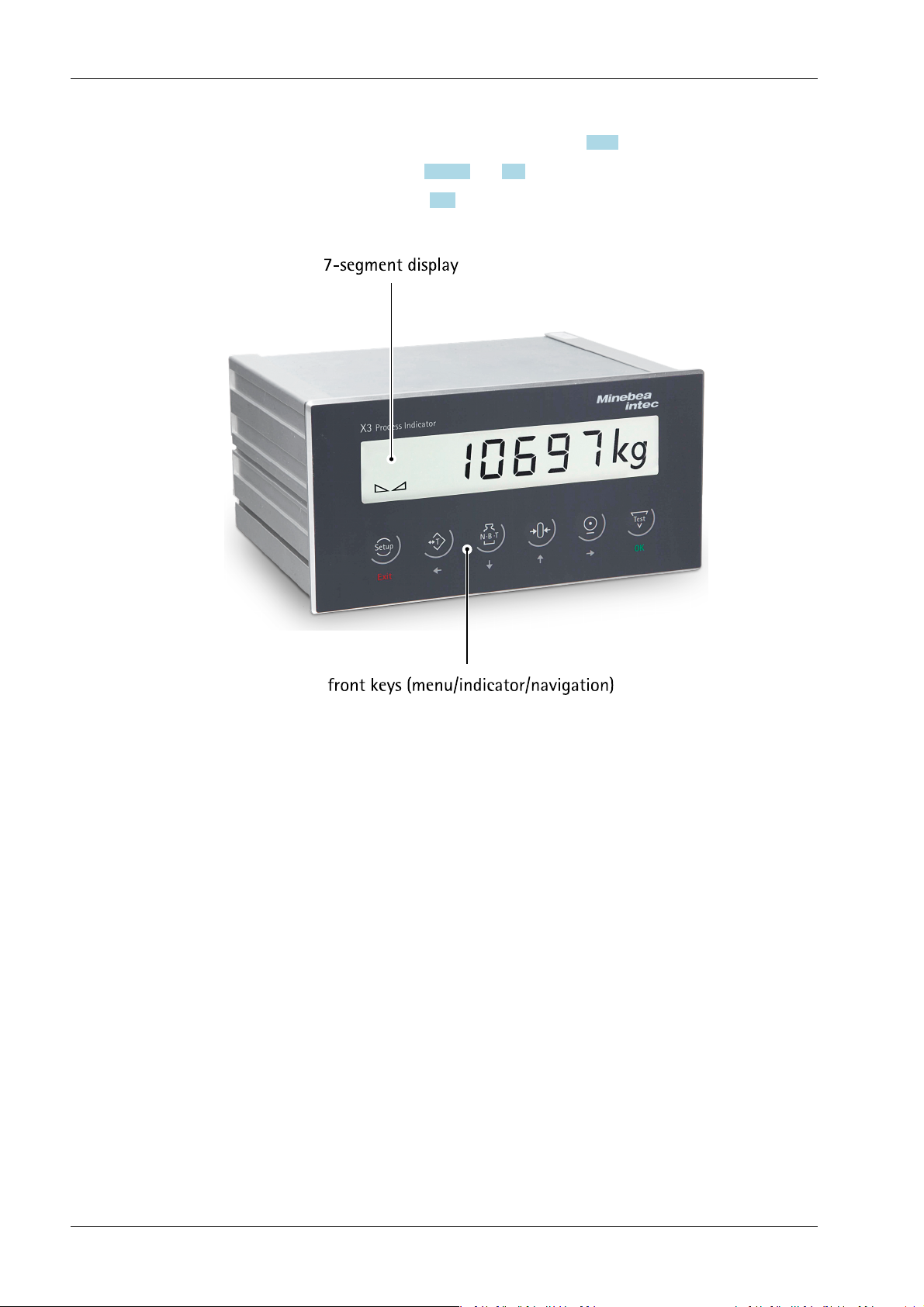
3.1 General information
The device is equipped with a 6-position, 7-segment display and additional status
indicators. Local operation can be carried out using 6 dual-function keys.
The device contains two applications:
- Standard
- EasyFill
Most functions are supported by both applications.
Some functions depend on the application.
3.2 Overview of the device
- Accuracy 10,000 e (class III) for the weighing electronics
- High-speed conversion with measurement times from 10 msec
- Weight display with status via transective, 6-digit, 7-segment display
- Alibi memory
- 6 function keys for operation on the front panel
- Enclosed front: IP65, back: IP30
- LAN adapter with 10/100 Mbit/s for data transfer, calibration, parameterization
- Integrated RS-232 interface for, e.g., printer or remote display
- Can be expanded using the following plug-in cards (2 slots):
- Serial input and output board 2× PR 5510/02 or 2× PR 5510/04
1× PR 5510/02 and/or 1× PR 5510/04
- Analog input and output board PR 5510/07
- BCD output board PR 5510/08 or PR 5510/09
- Opto-decoupled input and output board PR 5510/12
- Fieldbus cards PR 1721/3x
- Electrically isolated interfaces (except RS-232)
- Wide range power supply for 100 to 240 V AC, protection class I (protective
grounding conductor)
- Version PR 5410/01 for 24 V direct current
- Plug-in connections inside the device for load cells, inputs/outputs, LAN adapter
- Installation as control panel or control cabinet device
- Calibration using the front-panel keys or PC tool (browser/VNC); calibration of
Pendeo® load cells using the PC tool only
- Calibration using weights according to the mV/V method or directly using load cell
data (smart calibration)
- Software conguration of the interface cards, e.g., for remote display or printer
EN-15 Minebea Intec

X3 Process Indicator PR 5410 3 Device description
- The "EasyFill" application allows for quick and reliable lling and emptying of vessels
(for functional description, see Chapter 6.1).
- Analog test for the weighing electronics
- Overwrite protection using CAL switch on the main board
3.2.1 Communication protocols
For the internal RS-232 or external RS-232 + RS-485 (accessories):
- Remote display protocol
- Printer
- ModBus-RTU (slave)
- SMA protocol
- xBPI protocol
- EW-Com protocol
Fieldbus slave (accessories):
- PR 1721/31 ProBus-DP
- PR 1721/32 InterBus-S
- PR 1721/34 DeviceNet
- PR 1721/35 CC-Link
- PR 1721/36 ProNet I/O
- PR 1721/37 EtherNet IP
For the internal LAN:
- ModBus-TCP
- Ethernet TCP/IP
- OPC
3.3 Housing
3.3.1 General information
The device has an aluminum housing with IP65 front. It can also be used as a control
cabinet version.
The keypad and the display form one unit with the front. A rectangular cut-out is required
for the installation. Cable connections are made at the back of the housing.
The ambient conditions specied for the device must be observed (see Chapter 17.4.1).
Openings for max. 2 plug-in cards are sealed by dummy plates.
Minebea Intec EN-16
3 Device description X3 Process Indicator PR 5410
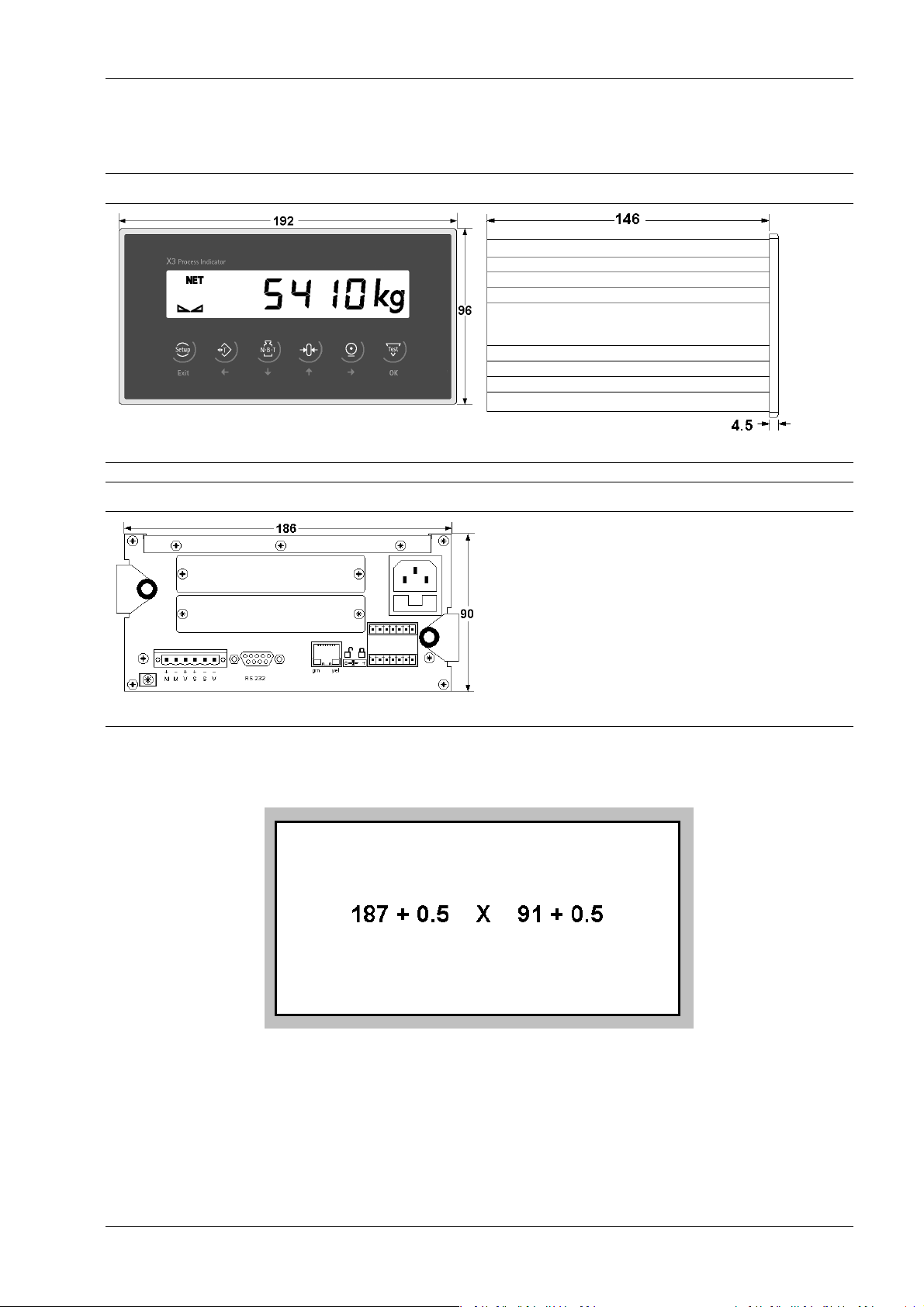
3.3.2 Dimensions
Front View Side View
all dimensions in mm
all dimensions in mm
Back View
all dimensions in mm
3.3.3 Control panel cut-out
The control panel cut-out must be made before installing the device.
all dimensions in mm
3.4 Display and control panel
3.4.1 General information
The PR 5410 process indicator can only be operated using the front-panel keys or by
Notebook/PC.
EN-17 Minebea Intec
X3 Process Indicator PR 5410 3 Device description
- Operation using the front-panel keys (see Chapter 7.5.2)
- VNC viewer (see Chapters 3.4.4.4 and 7.11) or
- WEB browser (see Chapter 7.12)
3.4.2 Overview
3.4.3 Display
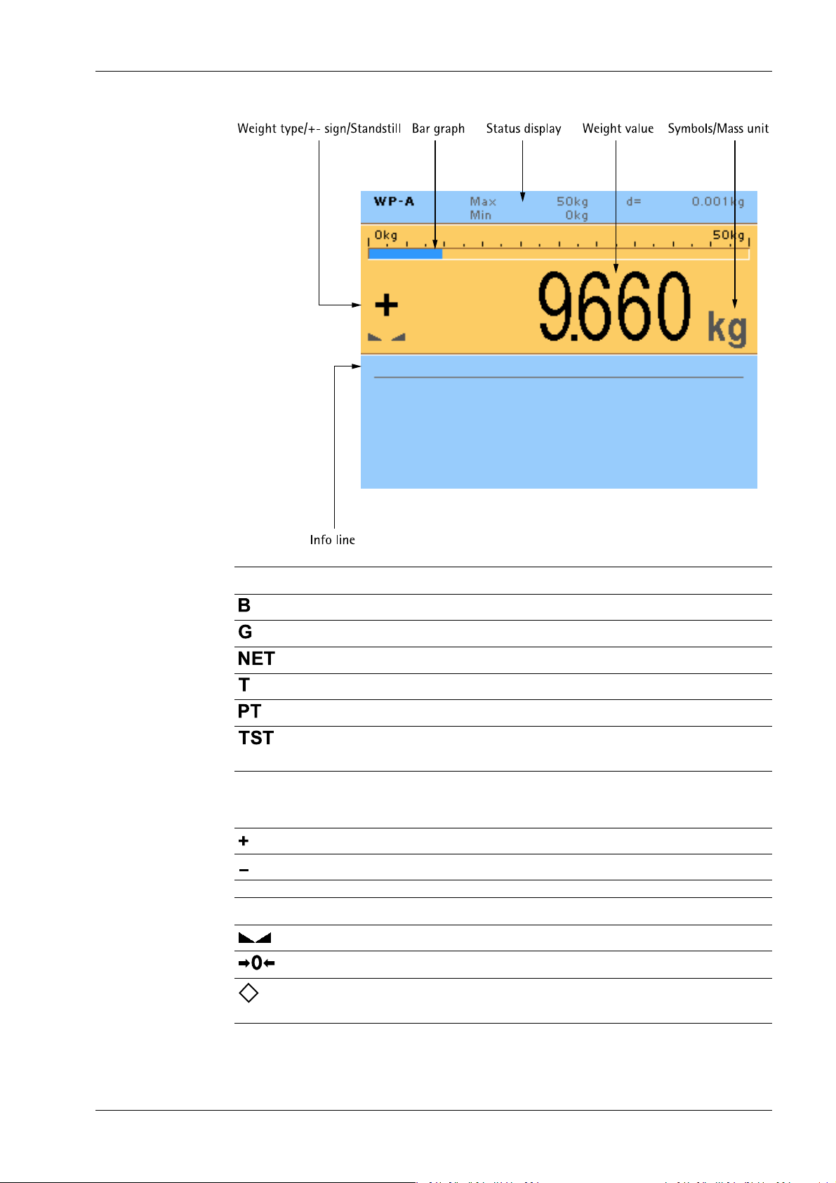
3.4.3.1 User interface
The display of the user interface shows weight values of up to 7‑digits with decimal point
and plus or minus sign.
Available weight units are t, kg, g or lb.
lb unit is not permitted as legal-for-trade in the EU and EEA.
Above the weight display of the user interface, the currently displayed weight is shown as
a bar graph in relation to the maximum load (Max). When Max reaches 100%, the bar
graph is located on the right.
Minebea Intec EN-18
3 Device description X3 Process Indicator PR 5410
Weight type/plus or minus sign Description
Gross weight
Gross weight in NTEP or NSC mode
Net weight (Net = gross - tare)
Tare weight
Preset tare
The display shows the test value without weight
unit.
No display - Test value
- Gross, not tared
Positive value
Negative value
Standstill/Zero Description
Weight value standstill
The gross weight value is within ±¼ d of zero.
Batching mode; ashes when "On hold"; ashes rapidly to indicate error.
EN-19 Minebea Intec
X3 Process Indicator PR 5410 3 Device description
Symbols/mass unit Description
Value not permissible in legal metrology
(e.g.,‑10-fold resolution, deactivated load cell).
R1 Range 1
R2 Range 2
R3 Range 3
WP A Weighing point A
Max Maximum load (weighing range)
Min Minimum weight
t, kg, g, lb These weight units are available.
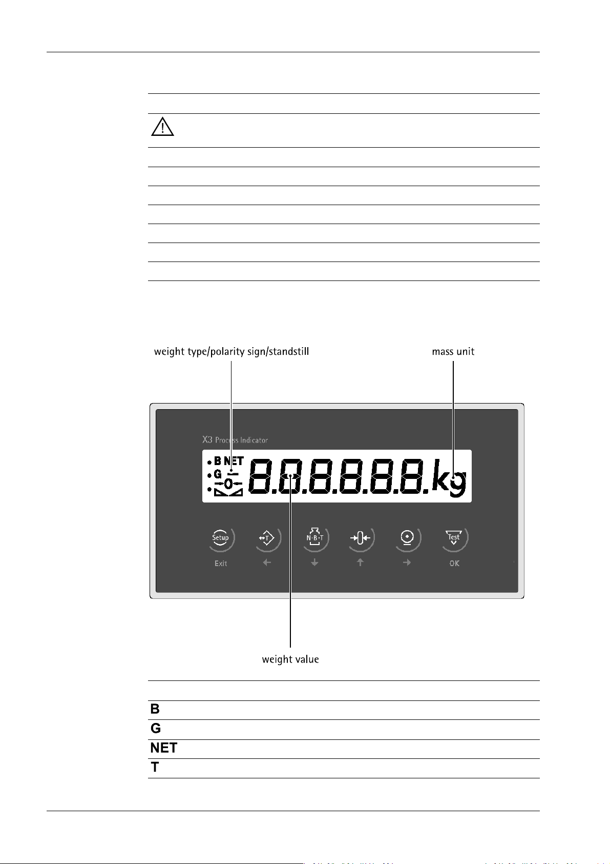
3.4.3.2 Device display
The display of the device permits indication of 6-digit weight values (digit height 18 mm)
with decimal point.
Weight type/plus or minus sign Description
Gross weight
Gross weight in NTEP or NSC mode
Net weight (Net = gross - tare)
Tare weight
Minebea Intec EN-20

3 Device description X3 Process Indicator PR 5410
Weight type/plus or minus sign Description
Fixed tare
No display - Test value
- Gross, not tared
The display shows the test value without weight
unit.
Positive value
Negative value
Standstill/zero/dosing Description
Weight value standstill
The gross weight value is within ±¼ d of zero.
Filling mode; ashes when batching is stopped; rapidashing indicates error.
Symbols/mass unit Description
• Range 1
•
•
•
•
•
t, kg, g, lb These weight units are available.
3.4.4 Operating elements
3.4.4.1 User interface
The following tables show the basic meanings of symbols on the operator interface.
Indicator keys
Display gross weight Sets gross weight to zero, provided that
Range 2
Range 3
- weight value is stable;
- weight is within zero setting range.
This function depends on the conguration.
Display tare weight. Starts a printout.
EN-21 Minebea Intec

X3 Process Indicator PR 5410 3 Device description
Indicator keys
Taring
The current gross weight is stored in
the tare memory, provided that
- weight value is stable;
- the instrument is not in error sta-
tus.
This function depends on the conguration.
Navigation/menu keys
Scroll up in the menu. Conrm input/selection.
Scroll down in the menu. - Backspace
- Pressing the delete key deletes indivi-
dual characters (within an entry).
- Cursor to the left
- Selection
- Cursor to the right
- Selection
Function keys/softkeys
Access the Setup menu.
Information on version number, tted
hardware, 10-fold resolution
- Cancel entry/selection (after a conr-
mation prompt) without saving the change.
- Exit parameters/menu window.
Depending on the settings under
-[Weighingpoint]- [Calib]- [Param]- [Test
mode] the following is displayed by calling
the test with the key later on:
- with "Absolute" the maximum load
- with "Relative" the deviation from test
value.
Softkeys 1…5
Select appropriate menu function, see also
Chapter 3.4.4.2.
No function
Minebea Intec EN-22
3 Device description X3 Process Indicator PR 5410
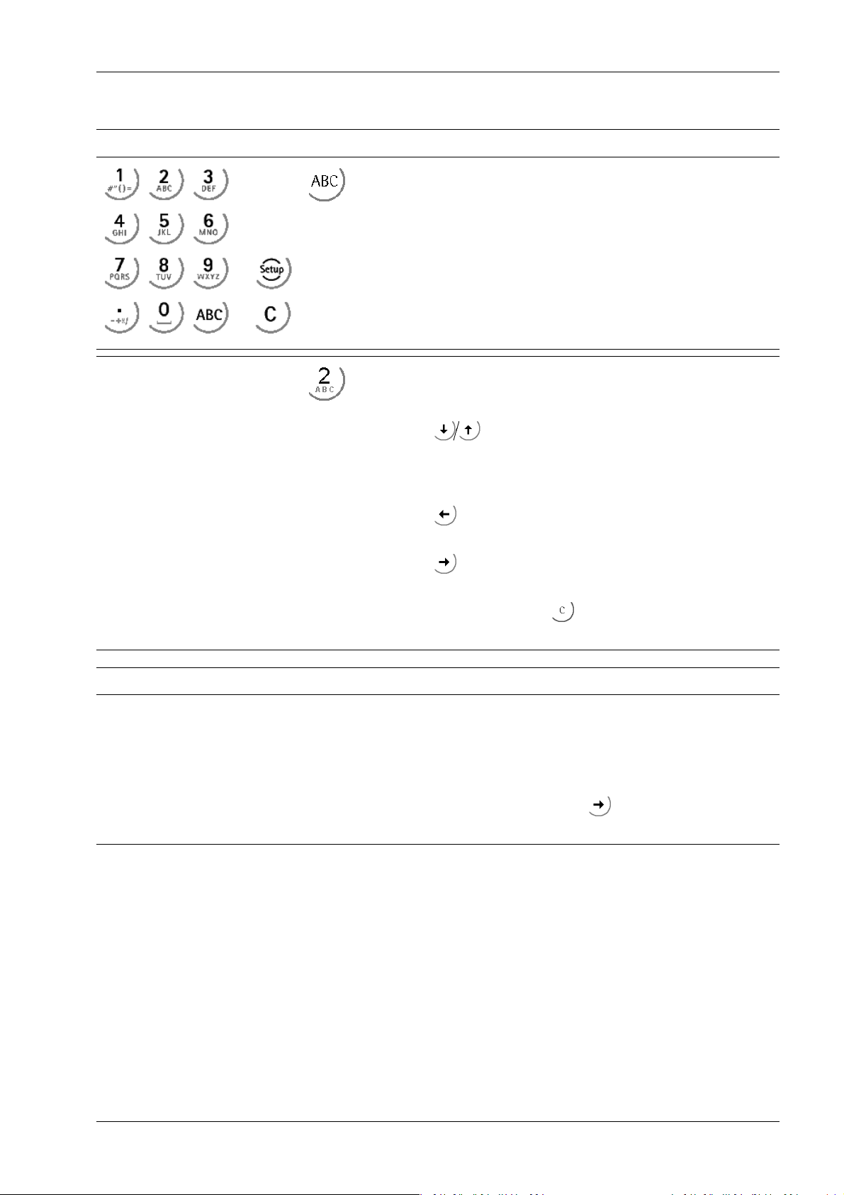
Alphanumeric keypad
Toggle key
Toggle by pressing:
- between alpha and numerical mode
- during conguration between weight units
Pressing once displays the corresponding rst character, e.g.,"A",
at the cursor position. After pressing twice, "B" is displayed at the
cursor position and after pressing three times, "C" is displayed.
Press the cursor key to nish entering a character or wait
approx. 2 seconds.
If only numeric values are required for input, letters are not enabled.
Input eld
Press the cursor key within an entry to return to the previous
character.
Press the cursor key within an entry to select the next character.
Within an input, pressing the delete key deletes the character
to the left of the cursor.
In principle
If alphanumeric characters are already present in the input eld of
the selected line, they will be completely overwritten after immediate entry.
If alphanumeric characters are already present in the input eld of
the selected line, you can press the cursor key to select the
characters to be overwritten and overwrite them.
EN-23 Minebea Intec
X3 Process Indicator PR 5410 3 Device description
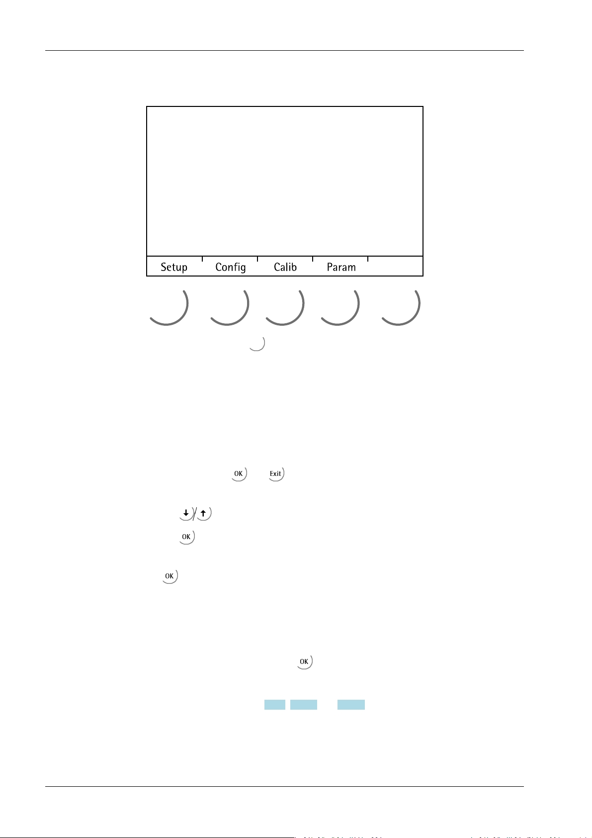
3.4.4.2 Operation using softkeys
The functions of the ve softkeys below the graphic display are indicated in the
bottommost text line of the display. Softkey functions shown in gray cannot be selected
at the active menu level or with the current access privileges.
In the descriptions of operating sequences which entail the use of softkeys, the softkey
function to be selected is shown in square brackets; the softkey symbol is not displayed;
example: [Calib].
3.4.4.3 Navigation key operation Menu
The cursor keys, the and keys are used to navigate through the menus.
Parameters
Use the cursor keys to select the individual parameters.
Use the key to conrm the selection.
The required values | texts are entered via the alphanumeric keys.
The key is used to check the ☑ box.
If the list of parameters is long, a vertical bar graph on the left (black and gray) shows
which part of the list is displayed.
An arrow in front of a menu item indicates that there are menu sublevels.
Possible settings and an available selection list is indicated by double arrows.
The parameter is selected using the key.
3.4.4.4 Operation using VNC
User interface, see Chapters 3.4.2, 3.4.3.1 and 3.4.4.1.
Minebea Intec EN-24
3 Device description X3 Process Indicator PR 5410
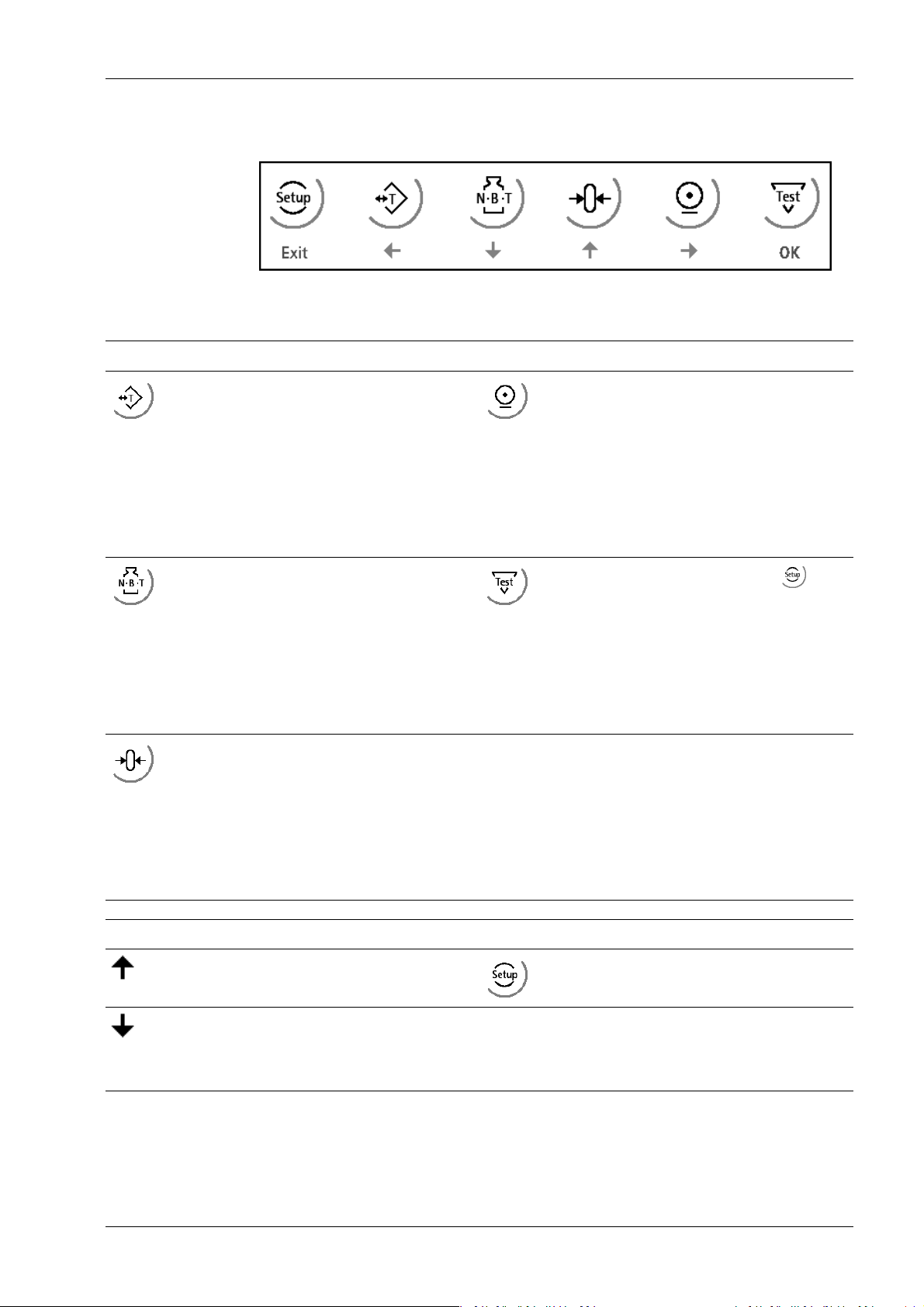
3.4.4.5 Operation using the front-panel keys
The following table shows the basic meanings of the symbols on the front-panel keys.
Indicator keys
Taring
The current gross weight is stored in
the tare memory, provided that
- weight value is stable;
- the instrument is not in error sta-
tus.
The key is locked during the lling
process.
Toggling the display
Net - gross - tare
The key is locked during the lling
process.
Sets gross weight to zero, provided
that
- weight value is stable;
- weight is within zero setting ran-
ge.
Starts a printout.
Depending on the settings under
-[Weighingpoint]- [Calib]- [Param]- [Test
mode] the following is displayed by calling
the test with the key later on:
- with "Absolute" the maximum load
- with "Relative" the deviation from test
value.
The key is locked during the lling
process.
Navigation/menu keys
Scroll up in the menu. Access the Setup menu.
Scroll down in the menu. OK - Conrm input/selection.
- Start/restart the ongoing lling pro-
cess.
EN-25 Minebea Intec

X3 Process Indicator PR 5410 3 Device description
Navigation/menu keys
- Cursor to the left
- Selection
- Cursor to the right
- Selection
3.4.4.5.1 Selecting parameters
The selection and modication of parameters are described in the following.
1. Press .
2. Press /OK.
The "Cd" calibration menu ashes.
Exit - Cancel entry/selection (after a conr-
mation prompt) without saving the change.
- Exit parameters/menu window.
- Stop/abort the ongoing lling process.
SEtuP appears on the display.
Cd 000 appears on the display.
3. Press to access the next parameter group.
CP ashes on the display.
4. Press to access the parameter number.
CP 010 appears on the display. The right digit ashes.
5. Press / to select the digits.
6. Press / to increase/decrease the number.
7. Press /OK to select the menu item.
The menu item appears on the display.
8. Press /OK to switch to the parameter selection.
9. Press / to select the parameter values.
10. Press /OK to select the parameter values.
11. Press "Exit" to exit a menu.
If a parameter was changed, SAVE
appears on the display.
12. Press /OK.
YES appears on the display.
Minebea Intec EN-26

3 Device description X3 Process Indicator PR 5410
13. Press if necessary, to select "no."
14. Press /OK to save the change.
EN-27 Minebea Intec
X3 Process Indicator PR 5410 3 Device description
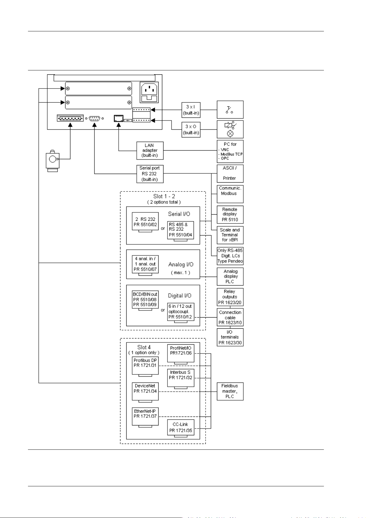
3.5 Overview of connections
Minebea Intec EN-28
 Loading...