

Minebea Intec PR 5220, PR 5220/01, PR 5220/04, PR 5220/00, PR 5220/07 Instrument Manual
...
Presented By
Dallas HoustonAustinFt Worth
NicolScales.com
800.225.8181
Contact Us
Nicol Scales & Measurement is an ISO Accredited Calibration
Company that has provided calibration, repair and sales of all types
of weighing and measurement products since 1931.

Instrument manual
Transmitter Series PR 5220
Translation of the original instrument manual 9499 050 52201 Edition 10.1.1 05/24/2017
Release 4.50
Minebea Intec GmbH, Meiendorfer Str. 205 A, 22145 Hamburg, Germany
Phone: +49.40.67960.303 Fax: +49.40.67960.383

Foreword
Must be followed!
Any information in this document is subject to change without notice and does not represent a commitment on
the part of Minebea Intec unless legally prescribed. This product should be operated only by trained and
qualied personnel. In correspondence concerning this product, the type, designation and version number as
well as all license numbers relating to the product have to be cited.
Note
The complete product is protected by copyright. It may not be changed or copied, and it may not be used
without purchasing or written permission from the copyright owner (Minebea Intec). Its use constitutes
acceptance by you of the above-mentioned provisions.

Transmitter Series PR 5220 Table of contents
Table of contents
1 Introduction......................................................................................................................................... 7
1.1 Read the manual......................................................................................................................................................... 7
1.2 This is what instructions look like............................................................................................................................. 7
1.3 This is what lists look like........................................................................................................................................... 7
1.4 This is what menus and soft keys look like............................................................................................................. 7
1.5 This is what safety instructions look like................................................................................................................. 7
1.6 Hotline..........................................................................................................................................................................8
2 Safety instructions............................................................................................................................... 9
2.1 General information................................................................................................................................................... 9
2.2 Intended use................................................................................................................................................................ 9
2.3 Incoming goods inspection....................................................................................................................................... 9
2.4 Before operational startup........................................................................................................................................9
2.4.1 Installation ........................................................................................................................................................9
2.4.2 Supply voltage connection........................................................................................................................... 10
2.4.3 Protective conductor connection................................................................................................................ 10
2.5 RF interference suppression................................................................................................................................... 10
2.6 Failure and excessive stress.................................................................................................................................... 10
2.7 Important note........................................................................................................................................................... 11
2.8 Repairs and maintenance......................................................................................................................................... 11
2.8.1 General information ....................................................................................................................................... 11
2.8.2 Electrostatically sensitive parts ....................................................................................................................11
2.8.3 Replacing fuses ............................................................................................................................................... 11
3 Device description ..............................................................................................................................12
3.1 Transmitter versions .................................................................................................................................................12
3.1.1 General information .......................................................................................................................................12
3.1.2 PR 5220/00.....................................................................................................................................................12
3.1.3 PR 5220/01 ProBus DP................................................................................................................................12
3.1.4 PR 5220/04 DeviceNet ..................................................................................................................................13
3.1.5 PR 5220/06 ProNet I/O...............................................................................................................................13
3.1.6 PR 5220/07 EtherNet IP ................................................................................................................................13
3.2 General information..................................................................................................................................................13
3.3 Overview of the device .............................................................................................................................................13
3.3.1 Communication protocols............................................................................................................................ 14
3.4 Housing...................................................................................................................................................................... 14
3.4.1 Sticker .............................................................................................................................................................. 14
3.4.2 Dimensions ......................................................................................................................................................15
3.5 Display and control panel.........................................................................................................................................15
3.5.1 General information .......................................................................................................................................15
3.5.2 Overview.......................................................................................................................................................... 16
EN-1 Minebea Intec

Transmitter Series PR 5220 Table of contents
3.5.3 Display ............................................................................................................................................................. 16
3.5.4 Operating elements....................................................................................................................................... 19
3.6 Overview of connections.........................................................................................................................................23
4 Device installation..............................................................................................................................24
4.1 General information.................................................................................................................................................24
4.2 Mechanical preparation...........................................................................................................................................24
4.2.1 Control cabinet units .....................................................................................................................................24
4.3 EMC-compliant installation ....................................................................................................................................25
4.4 Hardware construction ............................................................................................................................................26
4.4.1 Notes for connection.....................................................................................................................................26
4.4.2 Network port...................................................................................................................................................26
4.4.3 RS-485 interface............................................................................................................................................28
4.4.4 Analog outputs............................................................................................................................................... 33
4.4.5 Digital inputs ..................................................................................................................................................34
4.4.6 Digital outputs................................................................................................................................................36
4.4.7 Connecting analog load cells and platforms .............................................................................................38
4.5 Interfaces ...................................................................................................................................................................47
4.5.1 ProBus-DP interface ...................................................................................................................................47
4.5.2 DeviceNet interface .......................................................................................................................................50
4.5.3 ProNet I/O interface.....................................................................................................................................51
4.5.4 EtherNet-IP interface ....................................................................................................................................52
5 "Standard" application ......................................................................................................................54
5.1 Functions....................................................................................................................................................................54
5.1.1 General information ......................................................................................................................................54
5.1.2 Display functions............................................................................................................................................54
6 "EasyFill" application......................................................................................................................... 55
6.1 Functions....................................................................................................................................................................55
6.1.1 General information ......................................................................................................................................55
6.1.2 Display functions............................................................................................................................................55
6.1.3 Filling mode ....................................................................................................................................................55
6.2 Application menu [Start] .........................................................................................................................................55
7 Commissioning................................................................................................................................... 57
7.1 Power failure/Data backup/Restart ......................................................................................................................57
7.1.1 Power failure................................................................................................................................................... 57
7.1.2 Data backup.................................................................................................................................................... 57
7.1.3 Overwrite protection..................................................................................................................................... 57
7.1.4 Restart .............................................................................................................................................................59
7.2 Switching on the device...........................................................................................................................................59
7.3 Switching o the device ..........................................................................................................................................60
7.4 Warm-up time...........................................................................................................................................................60
Minebea Intec EN-2

Transmitter Series PR 5220 Table of contents
7.5 Finding and connecting the device automatically in the network....................................................................60
7.6 Finding and connecting a device with a notebook/PC....................................................................................... 61
7.7 Searching the device in the network with "IndicatorBrowser".......................................................................... 61
7.8 Resetting the network address ..............................................................................................................................63
7.9 Operation using VNC ...............................................................................................................................................63
7.10 Operation via a web browser..................................................................................................................................65
7.11 System setup.............................................................................................................................................................65
7.11.1 Serial ports parameter ..................................................................................................................................66
7.11.2 Operating parameter ....................................................................................................................................66
7.11.3 Fieldbus parameter........................................................................................................................................66
7.11.4 Network parameter .......................................................................................................................................66
7.11.5 Weighing points .............................................................................................................................................67
7.11.6 Limit parameter.............................................................................................................................................. 73
7.11.7 Digital I/O parameters .................................................................................................................................. 73
7.11.8 Analog output parameter............................................................................................................................. 73
7.12 Calibrating internal weighing point.......................................................................................................................74
7.12.1 General information ......................................................................................................................................74
7.12.2 Displaying calibration data...........................................................................................................................74
7.12.3 Selecting the calibration mode.................................................................................................................... 75
7.12.4 Setting maximum load.................................................................................................................................. 78
7.12.5 Determining the scale interval..................................................................................................................... 79
7.12.6 Determining the dead load ......................................................................................................................... 80
7.12.7 Calibrating with weight................................................................................................................................. 81
7.12.8 Calibrating with mV/V...................................................................................................................................82
7.12.9 Calibrating with load cell data (smart calibration)....................................................................................84
7.12.10 Subsequent dead load correction...............................................................................................................85
7.12.11 Linearization...................................................................................................................................................86
7.12.12 Calculating the test value .............................................................................................................................89
7.12.13 Saving the calibration....................................................................................................................................89
7.12.14 Cancelling a calibration.................................................................................................................................90
7.12.15 Parameter Input ............................................................................................................................................. 91
7.13 Calibrating xBPI-scale..............................................................................................................................................96
7.13.1 General information ......................................................................................................................................96
7.13.2 Parameters for serial interface ....................................................................................................................97
7.13.3 Parameters for the xBPI-weighing function..............................................................................................98
7.13.4 Setting up an xBPI platform.........................................................................................................................99
7.13.5 xBPI-parameter tables.................................................................................................................................101
7.13.6 Setting the xBPI dead load.........................................................................................................................104
7.13.7 xBPI calibration with user specied weight............................................................................................. 106
7.13.8 xBPI calibration with automatic weight detection ................................................................................. 107
7.13.9 xBPI calibration with default weight......................................................................................................... 108
7.13.10 xBPI calibration with built-in weight ........................................................................................................109
EN-3 Minebea Intec

Transmitter Series PR 5220 Table of contents
7.13.11 xBPI linearization.........................................................................................................................................109
7.14 Calibrating digital load cells of type "Pendeo" ...................................................................................................110
7.14.1 General information .....................................................................................................................................110
7.14.2 Selecting and conguring RS-485 interface .............................................................................................111
7.14.3 Selecting the load cell type .........................................................................................................................112
7.14.4 Calibration procedure ..................................................................................................................................112
7.14.5 Searching load cells ......................................................................................................................................113
7.14.6 Assigning load cells ......................................................................................................................................114
7.14.7 Calibrating load cells ....................................................................................................................................116
7.14.8 Assigning load cell names ...........................................................................................................................118
7.14.9 Service function.............................................................................................................................................118
7.14.10 Corner correction..........................................................................................................................................119
7.14.11 Terminating/saving calibration..................................................................................................................121
7.14.12 Parameter Input............................................................................................................................................121
7.14.13 Subsequent dead load correction ............................................................................................................. 123
7.14.14 Displaying weighing point serial number ................................................................................................124
7.15 General parameter settings .................................................................................................................................. 124
7.15.1 Selecting and conguring serial interfaces ............................................................................................. 125
7.15.2 Operating parameters................................................................................................................................. 130
7.15.3 Fieldbus parameters.................................................................................................................................... 132
7.15.4 Network parameters.................................................................................................................................... 135
7.15.5 Conguring limit values...............................................................................................................................137
7.15.6 Conguring digital inputs........................................................................................................................... 142
7.15.7 Conguring digital outputs........................................................................................................................ 145
7.15.8 Conguring analog output......................................................................................................................... 149
7.16 System information................................................................................................................................................ 150
7.16.1 Displaying the version..................................................................................................................................151
7.16.2 Displaying the status....................................................................................................................................151
7.16.3 Showing hardware options ........................................................................................................................ 152
7.16.4 Displaying Pendeo data.............................................................................................................................. 153
8 Production........................................................................................................................................157
8.1 General information............................................................................................................................................... 157
8.2 Starting the application ......................................................................................................................................... 157
8.3 Conguration via a notebook/PC ........................................................................................................................158
8.3.1 Conguring production mode................................................................................................................... 158
8.3.2 Conguring digital inputs and outputs..................................................................................................... 161
8.3.3 Conguring material ................................................................................................................................... 163
8.4 Filling ........................................................................................................................................................................166
9 Extended functions .......................................................................................................................... 168
9.1 Hardware test.......................................................................................................................................................... 168
9.1.1 Serial interfaces............................................................................................................................................ 168
Minebea Intec EN-4

Transmitter Series PR 5220 Table of contents
9.1.2 Inputs and outputs ...................................................................................................................................... 169
9.2 Functions via the WEB site .................................................................................................................................... 174
9.2.1 General information .................................................................................................................................... 174
9.2.2 Displaying weighing points in a table....................................................................................................... 175
9.2.3 Conguration printout................................................................................................................................ 175
9.2.4 Log les ..........................................................................................................................................................177
9.2.5 Screenshots................................................................................................................................................... 178
9.2.6 Error log......................................................................................................................................................... 179
9.2.7 Conguration data.......................................................................................................................................180
9.3 Resetting the device to the factory settings .......................................................................................................181
9.4 Updating new software with FlashIt.................................................................................................................... 182
9.4.1 Updating with a xed IP address .............................................................................................................. 182
10 ModBus protocol ............................................................................................................................. 186
10.1 General description ................................................................................................................................................186
10.2 SPM data in PR 1612 ModBus mode.................................................................................................................... 186
11 SMA protocol ................................................................................................................................... 188
11.1 General information............................................................................................................................................... 188
12 Fieldbus interface ............................................................................................................................ 189
12.1 Fieldbus interface conguration..........................................................................................................................189
12.2 Scale protocol (8-Byte) for the "standard" application .................................................................................... 189
12.2.1 Write window (input area)...........................................................................................................................190
12.2.2 Read window (output area) .........................................................................................................................191
12.2.3 Reading and writing data ............................................................................................................................191
12.2.4 Description of the I/O area (read/write window).................................................................................... 192
12.2.5 Special hints for DeviceNet and EtherNet-IP .......................................................................................... 197
12.2.6 Fieldbus register .......................................................................................................................................... 197
12.3 Filling protocol (64-Byte) for the "EasyFill" application .................................................................................. 202
12.3.1 Write window (input area).......................................................................................................................... 202
12.3.2 Read window (output area) ....................................................................................................................... 202
12.3.3 Indicator functions...................................................................................................................................... 202
12.3.4 Filling functions........................................................................................................................................... 202
12.3.5 Setup of the eldbus interface ................................................................................................................. 204
13 SPM .................................................................................................................................................. 211
13.1 General information................................................................................................................................................ 211
13.2 Elementary data types............................................................................................................................................211
13.3 Addressing............................................................................................................................................................... 212
13.4 System data............................................................................................................................................................. 212
14 Repairs and maintenance ..................................................................................................................217
14.1 Repairs...................................................................................................................................................................... 217
14.2 Maintenance............................................................................................................................................................ 217
EN-5 Minebea Intec

Transmitter Series PR 5220 Table of contents
14.3 Soldering work........................................................................................................................................................ 217
14.4 Cleaning ................................................................................................................................................................... 217
15 Disposal ........................................................................................................................................... 218
16 Error messages .................................................................................................................................219
16.1 Error messages measuring circuit........................................................................................................................ 219
16.2 Weight error status................................................................................................................................................ 220
16.3 Error messages for xBPI scales............................................................................................................................ 220
16.4 Error messages for Pendeo® load cells.............................................................................................................. 221
16.5 Error messages during calibration.......................................................................................................................222
16.6 Error numbers @ "LAST_ERROR" ........................................................................................................................224
16.6.1 Weighing point error ...................................................................................................................................224
16.6.2 Error in the "EasyFill" application..............................................................................................................224
17 Specications .................................................................................................................................. 226
17.1 Note on using "Free Software" .............................................................................................................................226
17.2 Decoding the serial number..................................................................................................................................226
17.3 General data ............................................................................................................................................................226
17.3.1 Supply voltage..............................................................................................................................................226
17.4 Eect of ambient conditions ................................................................................................................................226
17.4.1 Ambient conditions .....................................................................................................................................226
17.4.2 Electromagnetic Compatibility (EMC).......................................................................................................227
17.4.3 RF interference suppression ......................................................................................................................227
17.5 Weighing electronics..............................................................................................................................................227
17.5.1 Load cells.......................................................................................................................................................227
17.5.2 Principle.........................................................................................................................................................228
17.5.3 Accuracy and stability .................................................................................................................................228
17.5.4 Sensitivity......................................................................................................................................................228
17.5.5 Connecting cables........................................................................................................................................228
17.6 Mechanics ................................................................................................................................................................229
17.6.1 Design............................................................................................................................................................229
17.6.2 Weights..........................................................................................................................................................229
17.7 Documentation on the enclosed CD....................................................................................................................229
18 Appendix .........................................................................................................................................230
18.1 Spare parts.............................................................................................................................................................. 230
18.2 Test connector........................................................................................................................................................ 230
Minebea Intec EN-6

1 Introduction Transmitter Series PR 5220
1 Introduction
1.1 Read the manual
- Please read this manual carefully and completely before using the product.
- This manual is part of the product. Keep it in a safe and easily accessible location.
1.2 This is what instructions look like
1. - n. are placed before steps that must be done in sequence.
is placed before a step.
describes the result of a step.
1.3 This is what lists look like
- indicates an item in a list.
1.4 This is what menus and soft keys look like
[ ] frame menu items and soft keys.
Example:
[Start]- [Applications]- [Excel]
1.5 This is what safety instructions look like
Signal words indicate the severity of the danger involved when measures for preventing
hazards are not followed.
DANGER
Warning of personal injury
DANGER indicates that death or severe, irreversible personal injury will occur if
appropriate safety measures are not observed.
Take appropriate safety measures.
WARNING
Warning of potential health risk or risk of personal injury!
WARNING indicates that death or severe, irreversible injury may occur if appropriate
safety measures are not observed.
Take appropriate safety measures.
CAUTION
Warning of personal injury and/or property damage.
CAUTION indicates that minor, reversible injury or damage to property may occur if
appropriate safety measures are not observed.
Take appropriate safety measures.
EN-7 Minebea Intec

Transmitter Series PR 5220 1 Introduction
NOTICE
Warning of property and/or environmental damage.
ATTENTION indicates that damage to property and/or the environment may occur if
appropriate safety measures are not observed.
Take appropriate safety measures.
Note:
User tips, useful information and notes.
1.6 Hotline
Phone: +49.40.67960.444
Fax: +49.40.67960.474
E-mail: help@minebea-intec.com
Minebea Intec EN-8

2 Safety instructions Transmitter Series PR 5220
2 Safety instructions
2.1 General information
CAUTION
Warning of personal injury.
The product was in perfect condition with regard to safety features when it left the
factory.
To maintain this condition and to ensure safe operation, the user must follow the
instructions and observe the warnings in this manual.
2.2 Intended use
The device is intended for use as an indicator for weighing functions.
Product operation, commissioning and maintenance must be performed by trained and
qualied personnel who are aware of and able to deal with the related hazards and take
suitable measures for self-protection.
The device reects the state of the art.
The manufacturer does not accept any liability for damage caused by third-party system
components or due to incorrect use of the product. The use of this product signies
recognition of the stipulations listed above.
2.3 Incoming goods inspection
The shipment must be checked for completeness. A visual inspection must be performed
to determine if the shipment has been damaged. If there are grounds for a complaint, this
must be brought to the attention of the delivery company immediately. A Minebea Intec
sales or service point must be informed.
2.4 Before operational startup
NOTICE
Perform visual inspection!
Before operational startup as well as after storage or transport, inspect the device
visually for signs of mechanical damage.
2.4.1 Installation
The device is designed for mounting rail installation (35 mm as per DIN 46277).
NOTICE
Excessive heat may reduce the device lifetime.
When mounting on the rail, make sure that the distance from other instruments left
and right of the device is at least 20 mm.
EN-9 Minebea Intec

Transmitter Series PR 5220 2 Safety instructions
The device has to be installed in an EMC-compliant manner, see Chapter 4.3.
2.4.2 Supply voltage connection
The supply voltage is 24 V DC ±20%.
Max. power consumption:
- PR 5220/00: 6.5 W
- PR 5220/01: 8.5 W
- PR 5220/04: 8.5 W
- PR 5220/06: 8.5 W
- PR 5220/07: 8.5 W
For connection to 230/115 V AC, an external power supply (e.g., Minebea Intec PR 1624/
00 or Phoenix Mini Power) is required.
2.4.3 Protective conductor connection
The protective conductor is connected via the mounting rail.
2.5 RF interference suppression
The device is designed for operation in the industrial sector and can cause
RF interferences in a residential environment, see Chapter 17.4.3. In this case, the
operator can be required to carry out the appropriate measures.
2.6 Failure and excessive stress
If there is any reason to assume that safe operation of the device is no longer ensured,
shut it down and make sure it cannot be used.
Minebea Intec EN-10

2 Safety instructions Transmitter Series PR 5220
Safe operation is no longer ensured if any of the following is true:
- The device is physically damaged.
- The device does not function.
- The device has been subjected to stresses beyond the tolerance limits (e.g., during
storage or transport).
2.7 Important note
Make sure that the construction of the device is not altered to the detriment of safety. In
particular, leakage paths, air gaps (of live parts) and insulating layers must not be
reduced.
Minebea Intec cannot be held responsible for personal injury or property damage caused
by a device repaired incorrectly by an operator or installer.
2.8 Repairs and maintenance
2.8.1 General information
Repairs are subject to inspection and must be carried out at Minebea Intec.
In case of defect or malfunction, please contact your local Minebea Intec dealer or service
center for repair.
When returning the device for repair, please include a precise and complete description of
the problem.
Maintenance work may only be carried out by a trained technician with expert knowledge
of the hazards involved and the required precautions.
2.8.2 Electrostatically sensitive parts
This device contains electro-statically sensitive components. Therefore, potential
equalization must be provided when working on the device (antistatic protection).
2.8.3 Replacing fuses
The device has no replaceable fuse.
The load cell supply voltage is protected against short circuit.
On failure of load cell supply voltage the device must be disconnected from the power
supply; determine and eliminate the cause . Then the supply voltage can be switched on
again.
EN-11 Minebea Intec

Transmitter Series PR 5220 3 Device description
3 Device description
3.1 Transmitter versions
3.1.1 General information
The transmitter of the PR 5220 series exists in 5 versions. A later extension of the version
is not possible. Each type is clearly xed by the corresponding number. The front overlays
are adapted to the corresponding type.
PR 5220/00 PR 5220/01 PR 5220/04
3.1.2 PR 5220/00
PR 5220/06 PR 5220/07
This type has digital inputs and outputs as well as one analog output and a LAN-Adapter
for conguring and operating of the device. At the serial output e.g. a remote display can
be connected.
3.1.3 PR 5220/01 ProBus DP
In addition to PR 5220/00, the instrument is provided with a ProBus port.
Minebea Intec EN-12

3 Device description Transmitter Series PR 5220
3.1.4 PR 5220/04 DeviceNet
Additionally to the PR 5220/00 this instrument has a DeviceNet connection.
3.1.5 PR 5220/06 ProNet I/O
In addition to PR 5220/00, the instrument is provided with two ProNet I/O ports.
3.1.6 PR 5220/07 EtherNet IP
In addition to PR 5220/00, the instrument is provided with EtherNet-IP ports.
3.2 General information
The device contains two applications:
- Standard
- EasyFill
Most functions are supported by both applications.
Some functions depend on the application.
3.3 Overview of the device
- Precision 10.000 e according to OIML R76
- Internal resolution 7.5 million counter steps
- Linearity <0.002%
- Measure rate is congurable: 6100/sec
- Digital lter with adjustable characteristic line
- Electrically isolated interfaces
- 3 programmable pairs of limits
- 24 V DC supply voltage connection
- Connection via plug-in terminal blocks
- Socket for LAN adapter
- The device is snapped to a mounting rail.
- 5 Status LEDs for power supply, communication, error detection
- The "EasyFill" application allows for quick and reliable lling and emptying of
containers (for functional description, see Chapter 6.1).
The menu-guided calibration and conguration of the device are carried out on a
notebook/PC.
- Calibration using weights according to the mV/V method or using load cell data
(smart calibration)
- Analog output 0/420 mA, congurable for gross/net weight
- Analog value via eldbus
- 3 digital inputs, electrically isolated
- 3 digital outputs, electrically isolated
EN-13 Minebea Intec
Transmitter Series PR 5220 3 Device description
3.3.1 Communication protocols
For the internal RS-485:
- Remote display protocol
- ModBus-RTU (slave)
- SMA protocol
- xBPI protocol
Feldbus (slave):
- PR 5220/01 ProBus-DP
- PR 5220/04 DeviceNet
- PR 5220/06 ProNet I/O
- PR 5220/07 EtherNet-IP
For the internal LAN:
- ModBus-TCP
3.4 Housing
3.4.1 Sticker
- Ethernet-TCP/IP
- OPC
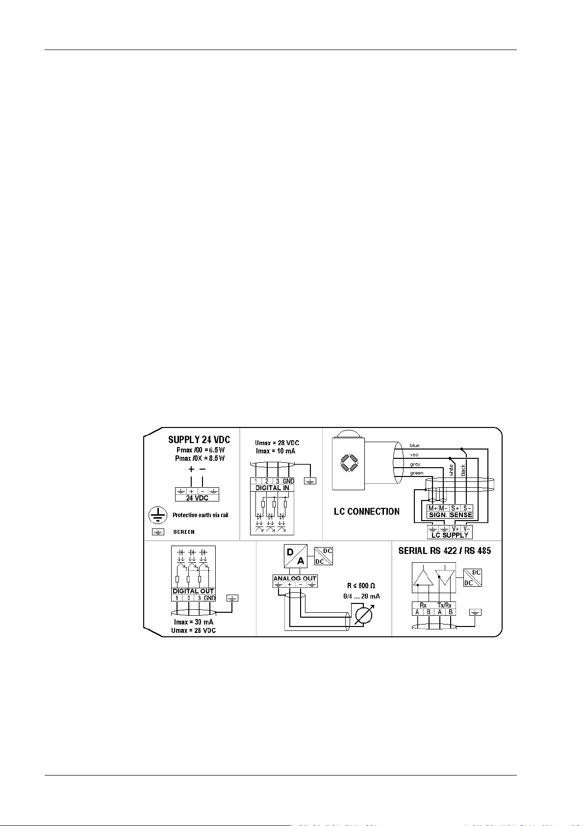
The connection diagram is located on the side of the housing.
Minebea Intec EN-14
3 Device description Transmitter Series PR 5220
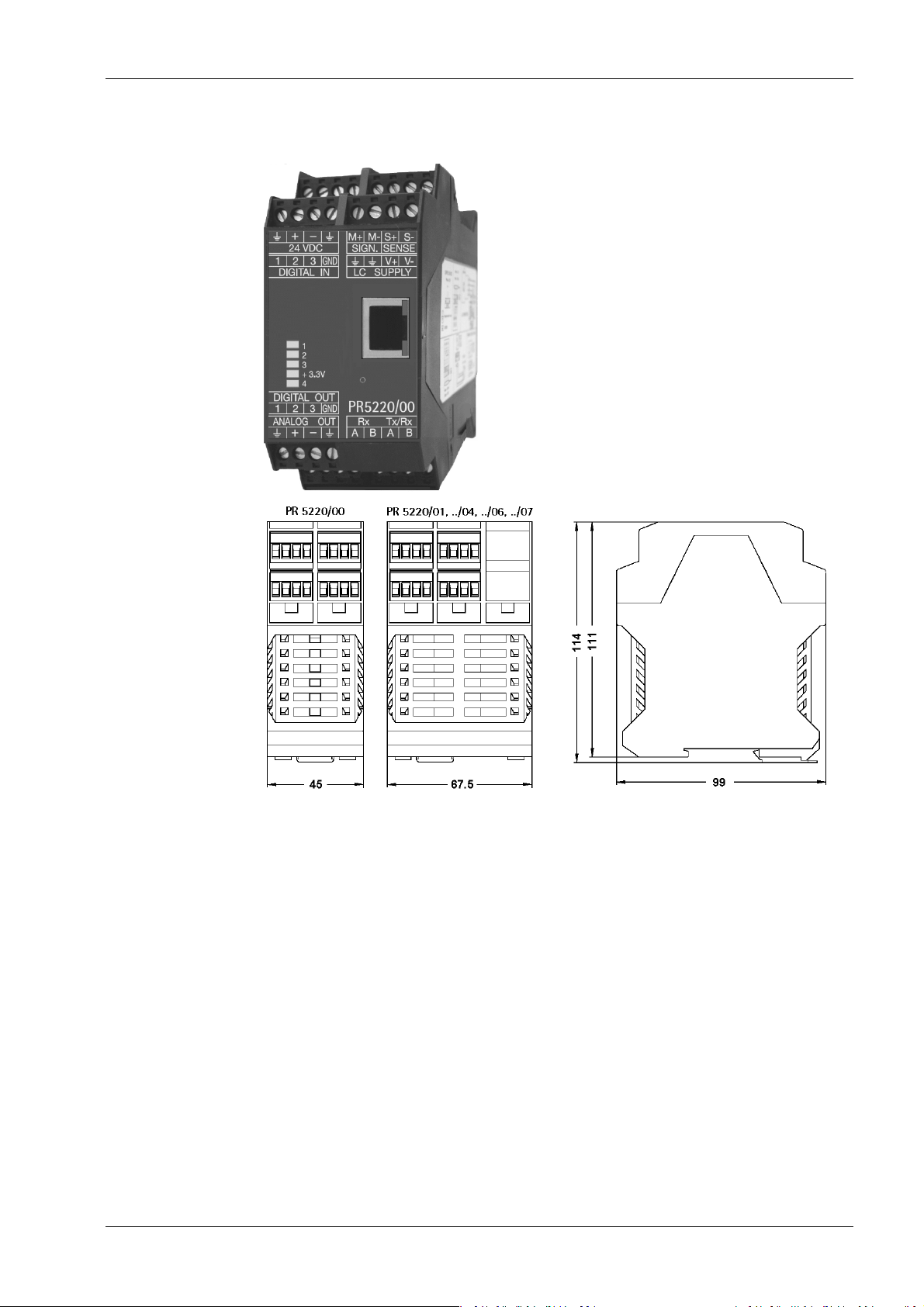
3.4.2 Dimensions
all dimensions in mm
3.5 Display and control panel
3.5.1 General information
The transmitter of the PR 5220 series can only be operated by Notebook/PC.
- VNC viewer (see Chapters 3.5.4.4 and 7.9) or
- WEB browser (see Chapter 7.10)
EN-15 Minebea Intec
Transmitter Series PR 5220 3 Device description
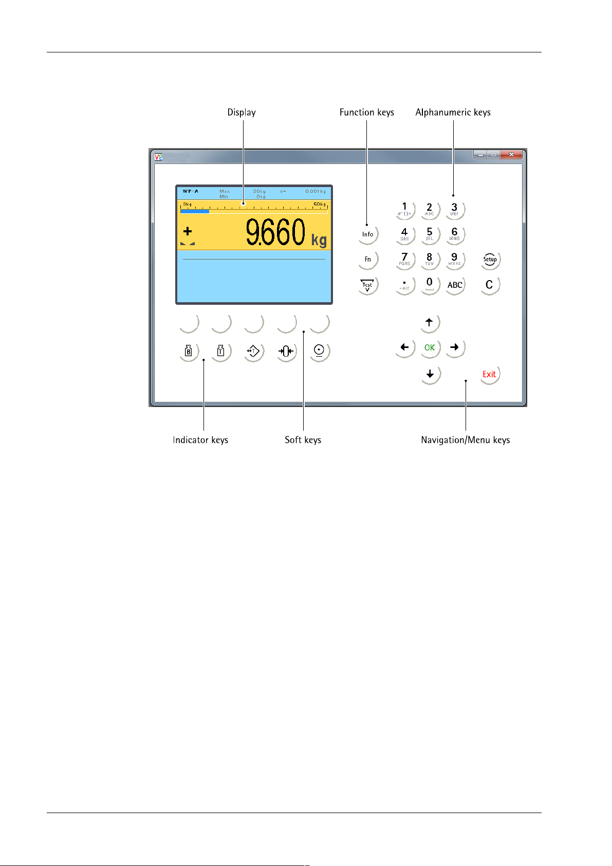
3.5.2 Overview
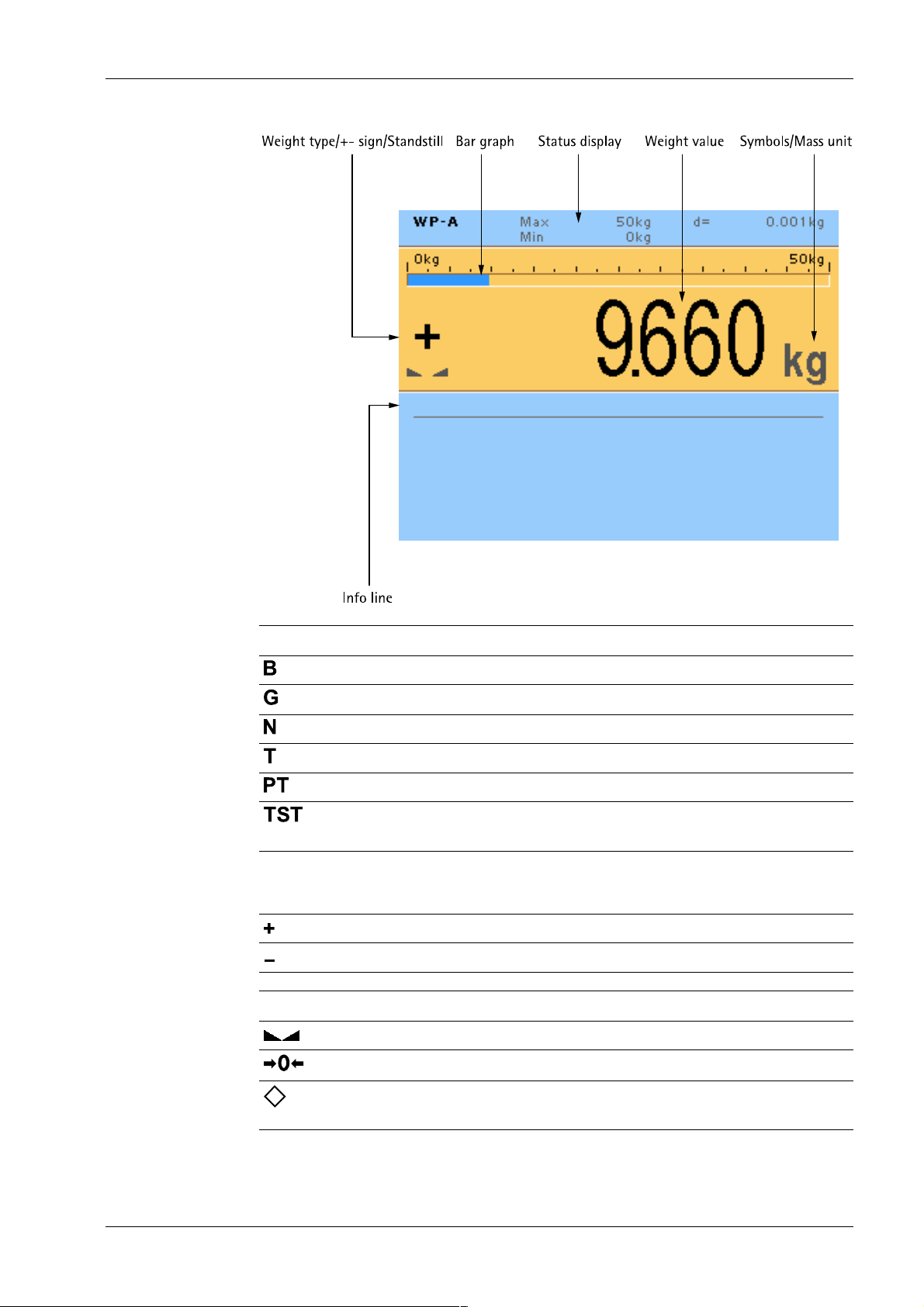
3.5.3 Display
3.5.3.1 User interface
The display of the user interface shows weight values of up to 7‑digits with decimal point
and plus or minus sign.
Available weight units are t, kg, g, mg, lb or oz.
Above the weight display of the user interface, the currently displayed weight is shown as
a bar graph in relation to the maximum load (Max). When Max reaches 100%, the bar
graph is located on the right.
Minebea Intec EN-16
3 Device description Transmitter Series PR 5220
Weight type/plus or minus sign Description
Gross weight
Gross weight in NTEP or NSC mode
Net weight (Net = gross - tare)
Tare weight
Preset tare
The display shows the test value without weight
unit.
No display - Test value
- Gross, not tared
Positive value
Negative value
Standstill/Zero Description
Weight value standstill
The gross weight value is within ±¼ d of zero.
Filling mode; ashes when batching is stopped; ashes rapidlyto indicate error.
EN-17 Minebea Intec
Transmitter Series PR 5220 3 Device description
Symbols/mass unit Description
Value not permissible in legal metrology
(e.g.,10-fold resolution, deactivated load cell).
R1 Range 1
R2 Range 2
R3 Range 3
WP A Weighing point A
Max Maximum load (weighing range)
Min Minimum weight
t, kg, g, mg, lb, oz These weight units are available.
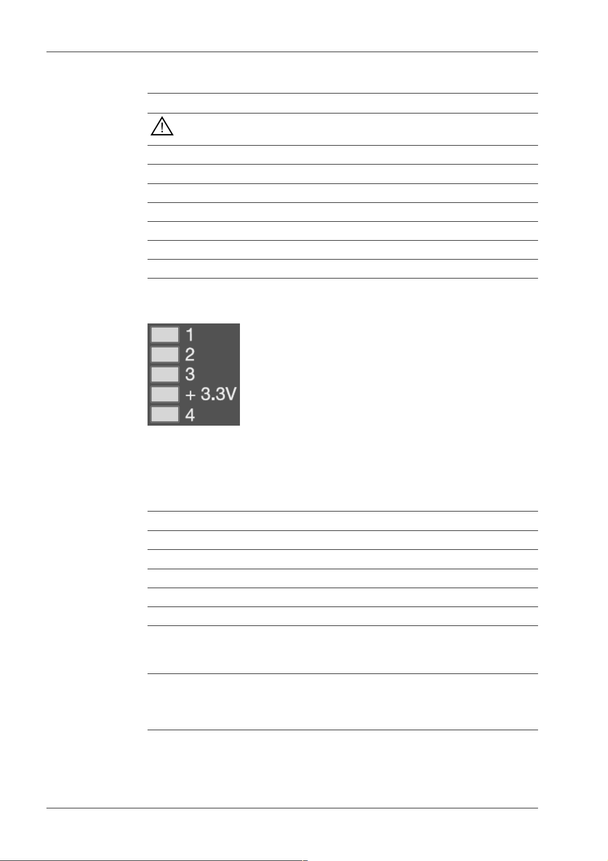
3.5.3.2 LEDs
The device has 5 green LEDs for the following status displays:
- Operational status
- Error status
Power supply, bus connection
LED Power on Bus Bus connection not provided
1
2
3
+3.3V lit
4 lit* ashing 1 Hz
* The LED for bus activity (PR 5220/01 and PR 5220/04) lights up as soon as there is a
connection.
Note:
The LED remains lit, even if there is no communication or the physical connection is
interrupted.
Minebea Intec EN-18

3 Device description Transmitter Series PR 5220
Weight status
LED Standstill ± Null < Null or > FSD
1 lit
2 lit
3 lit
+3.3V
4
Note:
For weight error status, see Chapter 16.2.
3.5.4 Operating elements
3.5.4.1 User interface
Indicator keys
Display gross weight Sets gross weight to zero, provided that
Display tare weight.
Taring
The current gross weight is stored in
the tare memory, provided that
- weight value is stable;
- the instrument is not in error sta-
tus.
This function depends on the conguration.
Navigation/menu keys
The following tables show the basic meanings of symbols on the operator interface.
- weight value is stable;
- weight is within zero setting range.
This function depends on the conguration.
Scroll up in the menu. Conrm input/selection.
Scroll down in the menu. - Backspace
- Pressing the delete key deletes indivi-
dual characters (within an entry).
EN-19 Minebea Intec

Transmitter Series PR 5220 3 Device description
Navigation/menu keys
- Cursor to the left
- Selection
- Cursor to the right
- Selection
Function keys/softkeys
Access the Setup menu.
Information on version number, tted
hardware, 10-fold resolution
- Cancel entry/selection (after a conr-
mation prompt) without saving the change.
- Exit parameters/menu window.
Depending on the settings under
-[Weighingpoint]- [Calib]- [Param]- [Test
mode] the following is displayed by calling
the test with the key later on:
- with "Absolute" the maximum load
- with "Relative" the deviation from test
value.
Softkeys 1…5
Select appropriate menu function, see also
Chapter 3.5.4.2.
No function
Alphanumeric keypad
Toggle key
Toggle by pressing:
- between alpha and numerical mode
- during conguration between weight units
Minebea Intec EN-20
3 Device description Transmitter Series PR 5220
Alphanumeric keypad
Pressing once displays the corresponding rst character, e.g.,"A",
at the cursor position. After pressing twice, "B" is displayed at the
cursor position and after pressing three times, "C" is displayed.
Press the cursor key to nish entering a character or wait
approx. 2 seconds.
If only numeric values are required for input, letters are not enabled.
Press the cursor key within an entry to return to the previous
character.
Press the cursor key within an entry to select the next character.
Within an input, pressing the delete key deletes the character
to the left of the cursor.
Input eld
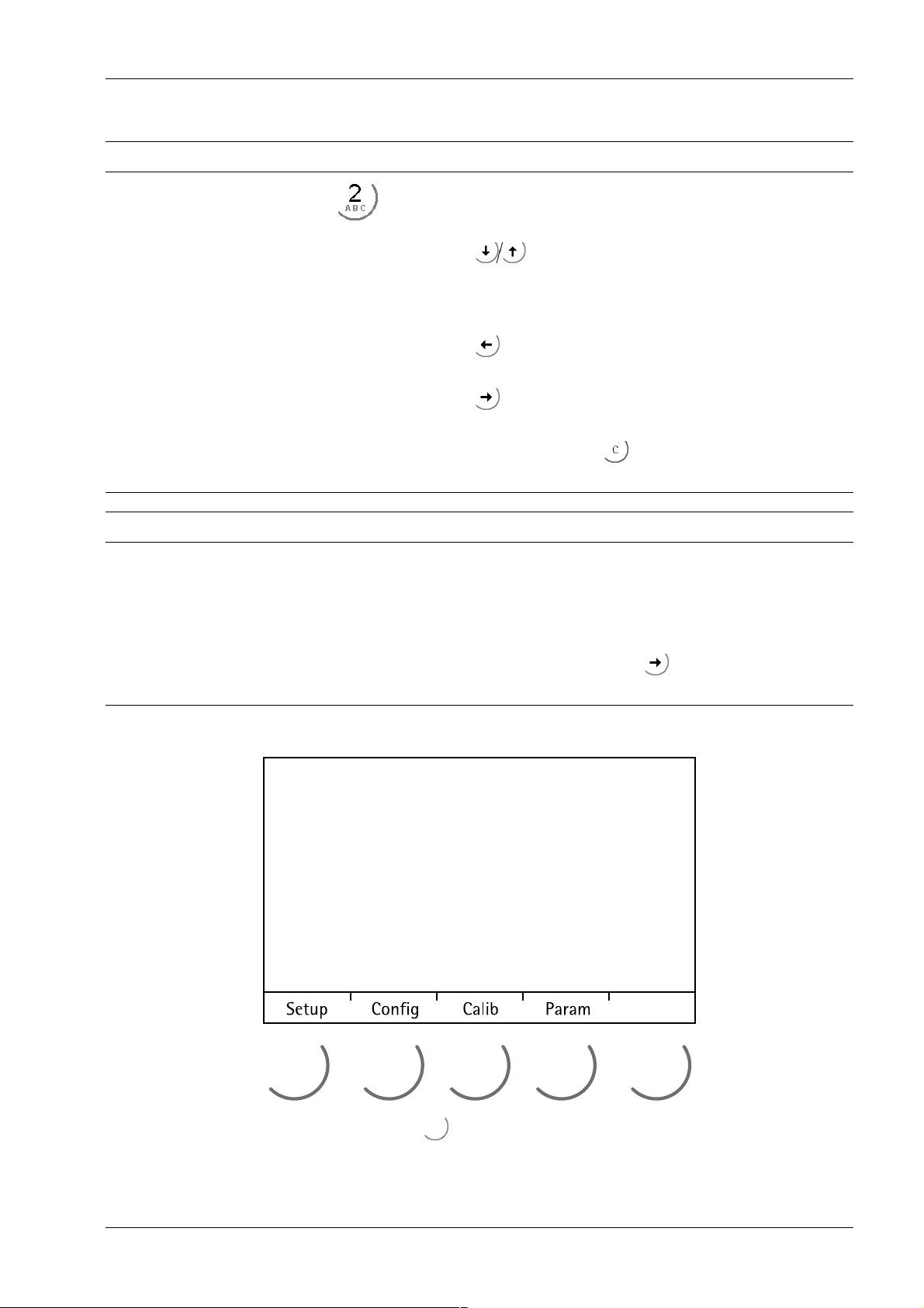
3.5.4.2 Operation using soft keys
In principle
If alphanumeric characters are already present in the input eld of
the selected line, they will be completely overwritten after immediate entry.
If alphanumeric characters are already present in the input eld of
the selected line, you can press the cursor key to select the
characters to be overwritten and overwrite them.
The functions of the ve soft keys below the graphic display are indicated in the
bottommost text line of the display. Soft key functions shown in gray cannot be selected
at the active menu level or with the current access privileges.
EN-21 Minebea Intec

Transmitter Series PR 5220 3 Device description
In the descriptions of operating sequences which entail the use of soft keys, the soft key
function to be selected is shown in square brackets; the soft key symbol is not displayed;
example: [Calib].
3.5.4.3 Navigation key operation
Menu
The cursor keys, the and keys are used to navigate through the menus.
Parameters
Use the cursor keys to select the individual parameters.
Use the key to conrm the selection.
The required values | texts are entered via the alphanumeric keys.
The key is used to check the ☑ box.
If the list of parameters is long, a vertical bar graph on the left (black and gray) shows
which part of the list is displayed.
An arrow in front of a menu item indicates that there are menu sublevels.
Possible settings and an available selection list is indicated by double arrows.
The parameter is selected using the key.
3.5.4.4 Operation using VNC
User interface, see Chapters 3.5.2, 3.5.3.1 and 3.5.4.1.
Minebea Intec EN-22

3 Device description Transmitter Series PR 5220
3.6 Overview of connections
EN-23 Minebea Intec

Transmitter Series PR 5220 4 Device installation
4 Device installation
4.1 General information
Before starting work, please read Chapter 2 and follow all instructions.
Note:
For use in UL-regulated applications:
The PR 5220 transmitter must be installed in an NTRL end-enclosure.
WARNING
Warning of a hazard area and/or risk of personal injury
All cable connections must be protected against damage.
Note:
- Measurement cables should be kept away from power equipment.
- Signal cables and measurement cables should be installed separately from electric
power lines.
- It is recommended to lay measurement cables in separate cable conduits.
- Data cables should be crossed at right angles.
Further procedures:
- Check the consignment: make sure that all components are present.
- Safety check: inspect all components for damage.
- Make sure that the on-site installation is correct and complete including cables, e.g.
power cable fuse protection, load cells, junction box, data cables, console/cabinet,
etc.
- Follow all device installation instructions related to application, safety, ventilation,
sealing and environmental inuences.
- Connect the cable from the junction box or platform/load cell.
- If applicable: connect other data cables, power cables, etc.
- Connect to power supply.
- Check the installation.
4.2 Mechanical preparation
4.2.1 Control cabinet units
Have all required parts, technical documents and tools at hand for installation.
Other procedures:
- Install device.
- Secure the cable at the place of installation; e.g., using cable ties.
Minebea Intec EN-24
4 Device installation Transmitter Series PR 5220
- Remove the insulation from the cable ends and keep the strands short.
- Connect the screens to the screen clamping rail using cable clamps, see Chapter 4.3.
- Establish equipotential bonding between instruments/system modules (mandatory
for Ex-applications.)
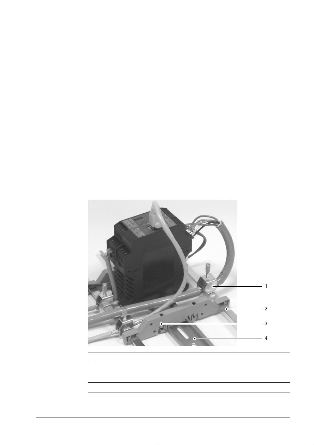
4.3 EMC-compliant installation
- Use only screened data cables.
- Connect screens on both sides to ground.
- Keep non-screened cable ends short.
- Make equipotential bonding conductor connections between screen clamping rail
and cabinet/housing.
- Use metal or metalized connector casings.
- Establish equipotential bonding between instruments/system modules (mandatory
for Ex-applications.
- Use standard reference potential.
- Connect mounting rail to protective earth.
- Install measure and data cables separately from power cables.
No. Description
1 Screen clamp (e.g. Phoenix SK8-D)
2 Screen rail (e.g. Phoenix NLS-CU 3/10)
3 Rail connector bracket (e.g. Phoenix AB-SK 65D)
4 Mounting rail (35 mm)
EN-25 Minebea Intec
Transmitter Series PR 5220 4 Device installation
4.4 Hardware construction
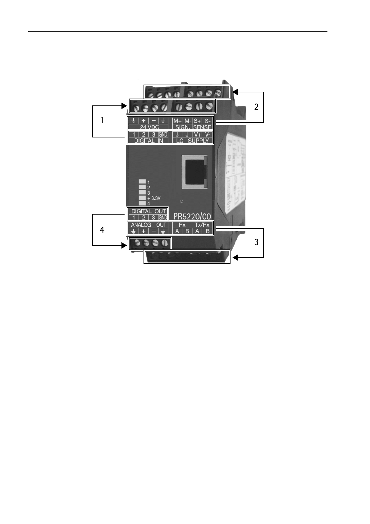
4.4.1 Notes for connection
The labels on the front side of the transmitter are assigned to the clamps as follows:
- Lower line to the front clamps (1)
- Upper line to the back clamps (2)
- Lower line to the back clamps (3)
- Upper line to the front clamp (4)
4.4.2 Network port
The device has an internal Ethernet port.
4.4.2.1 Ethernet port
The Ethernet port contains a powerful TCP/IP interface connection with transfer rates of
10 or 100 Mbit/s.
Function tests can be made via the LEDs (green and yellow) in the RJ-45 socket.
Minebea Intec EN-26

4 Device installation Transmitter Series PR 5220
Specications
Description Data
Connection RJ-45 socket on the device front
Transmission rates 10 Mbit/s, 100 Mbit/s, full/half duplex, auto-detection
Connection mode Point to point
Potential isolation Yes
Cable type CAT 5 patch cable, twisted pair, screened
Cable impedance
Cable length max. 115 m
4.4.2.2 Notebook/PC connection
green (grn): ashing on data trac (activity)
Yellow (yel): lights up when there is an existing connection
(link)
150
Remote operation of the device from a notebook/PC is possible (install VNC software
version 3.3.7* on the notebook/PC).
For the network address see Chapter7.7.
* Minebea Intec guarantees the functionality only if this version is used.
EN-27 Minebea Intec
 Loading...