

Minebea Intec Maxxis 5, PR5900 Operating Instructions Manual
Operating Instructions
Process Controller Maxxis 5 PR 5900
Translation of original operating instructions 9499 050 59900 Edition 6.1.1 02/26/2018
Release 2.26.xx-Exx
Minebea Intec GmbH, Meiendorfer Str. 205 A, 22145 Hamburg, Germany
Phone: +49.40.67960.303 Fax: +49.40.67960.383

Foreword
Must be followed!
Any information in this document is subject to change without notice and does not represent a commitment on
the part of Minebea Intec unless legally prescribed. This product should be operated/installed only by trained
and qualied personnel. In correspondence concerning this product, the type, name, and release number/serial
number as well as all license numbers relating to the product have to be cited.
Note
The product is partially protected by copyright. It may not be changed or copied, and it may not be used without
purchasing or written permission from the copyright owner (Minebea Intec). Its use constitutes acceptance by
you of the above-mentioned provisions.

Process Controller Maxxis 5 PR 5900 Table of contents
Table of contents
1 Introduction......................................................................................................................................... 6
1.1 Read the manual.........................................................................................................................................................6
1.2 This is what operating instructions look like..........................................................................................................6
1.3 This is what lists look like........................................................................................................................................... 6
1.4 This is what menu items and softkeys look like..................................................................................................... 6
1.5 This is what the safety instructions look like..........................................................................................................6
1.6 Hotline.......................................................................................................................................................................... 7
2 Commissioning..................................................................................................................................... 8
2.1 Display and control panel.......................................................................................................................................... 8
2.1.1 Overview............................................................................................................................................................8
2.1.2 Display elements..............................................................................................................................................8
2.1.3 Operating elements........................................................................................................................................ 11
2.1.4 Display and operation using VNC client..................................................................................................... 18
2.2 Data security and data storage .............................................................................................................................. 18
2.2.1 Power failure................................................................................................................................................... 18
2.2.2 Warm start....................................................................................................................................................... 18
2.2.3 Cold start ......................................................................................................................................................... 18
2.3 Switching on the device........................................................................................................................................... 19
2.4 Switching o the device..........................................................................................................................................20
2.5 Device warm-up time...............................................................................................................................................20
2.6 Operating via front-panel keys/PC keyboard......................................................................................................20
2.7 Overwrite protection................................................................................................................................................20
2.7.1 CAL switch.......................................................................................................................................................20
2.7.2 Software..........................................................................................................................................................22
2.8 Switching on blackbox device ................................................................................................................................24
2.8.1 Connecting to remote terminal PR 5900/6x, ../7x...................................................................................24
2.8.2 Network settings............................................................................................................................................24
2.8.3 Connecting to notebook/PC ........................................................................................................................25
2.9 Operating via a notebook/PC.................................................................................................................................26
2.9.1 Finding and connecting the device automatically in the network .........................................................26
2.9.2 Finding and connecting a device with a notebook/PC ............................................................................26
2.9.3 Searching the device in the network with "IndicatorBrowser" ...............................................................27
2.9.4 Resetting the network address....................................................................................................................29
2.9.5 Operation using VNC.....................................................................................................................................29
2.9.6 Operation via a web browser .......................................................................................................................30
3 Operation and control ........................................................................................................................ 32
3.1 User login/logout .....................................................................................................................................................32
3.1.1 User login ........................................................................................................................................................32
3.1.2 User Logout....................................................................................................................................................33
EN-1 Minebea Intec

Process Controller Maxxis 5 PR 5900 Table of contents
3.2 User management.................................................................................................................................................... 33
3.3 Selecting the operating language..........................................................................................................................34
3.4 System menu.............................................................................................................................................................34
3.5 Help functions...........................................................................................................................................................36
3.6 Alibi memory.............................................................................................................................................................36
3.7 Showing the calibration data.................................................................................................................................. 37
3.8 Increased resolution (10-fold) of the weight value .............................................................................................37
3.9 Functions via the website........................................................................................................................................ 37
3.9.1 Display weighing points in a table ..............................................................................................................39
3.9.2 Browse database........................................................................................................................................... 40
3.9.3 Browsing the Alibi memory......................................................................................................................... 40
3.9.4 Displaying manuals ....................................................................................................................................... 41
3.9.5 Browse the event log..................................................................................................................................... 41
3.9.6 Browse log les ..............................................................................................................................................42
3.9.7 Displaying a log of the last system error....................................................................................................42
3.9.8 Screenshot ......................................................................................................................................................43
3.9.9 Export database.............................................................................................................................................43
3.9.10 Export Alibi memory......................................................................................................................................44
3.9.11 Export service report.....................................................................................................................................44
3.9.12 Backup and restore setup data....................................................................................................................45
3.9.13 Loading language les..................................................................................................................................47
3.10 BIOS BOOT menu .....................................................................................................................................................47
3.10.1 Open BIOS BOOT menu................................................................................................................................48
3.10.2 BIOS BOOT menu in blackbox device.........................................................................................................54
3.10.3 System messages in blackbox device.........................................................................................................54
4 System setup......................................................................................................................................56
4.1 Connected devices ...................................................................................................................................................57
4.1.1 Remote display............................................................................................................................................... 57
4.1.2 ModBus-RTU master.....................................................................................................................................59
4.1.3 PC via EW-Com............................................................................................................................................... 61
4.1.4 Printer..............................................................................................................................................................63
4.1.5 Remote terminal .............................................................................................................................................71
4.1.6 Barcode scanner (with Ex approval).............................................................................................................71
4.2 Date & time ................................................................................................................................................................73
4.3 Operating parameters .............................................................................................................................................75
4.4 Network parameters ............................................................................................................................................... 80
4.5 Network share connections ....................................................................................................................................83
4.5.1 Add...................................................................................................................................................................84
4.5.2 Change.............................................................................................................................................................86
4.5.3 Remove............................................................................................................................................................87
4.6 Fieldbus parameters ................................................................................................................................................88
4.6.1 Fieldbus settings for the SPS .......................................................................................................................89
Minebea Intec EN-2

Process Controller Maxxis 5 PR 5900 Table of contents
4.7 Weighing points........................................................................................................................................................90
4.7.1 Internal weighing point.................................................................................................................................92
4.7.2 Liquid counter .............................................................................................................................................. 123
4.7.3 User scale ...................................................................................................................................................... 126
4.7.4 A+B (scale)..................................................................................................................................................... 129
4.7.5 xBPI scale ...................................................................................................................................................... 132
4.7.6 SBI scale......................................................................................................................................................... 157
4.7.7 Pendeo Truck.................................................................................................................................................161
4.7.8 Pendeo Process............................................................................................................................................ 187
4.7.9 PR-Net weighing point ............................................................................................................................... 213
4.7.10 Mettler-Scale ................................................................................................................................................216
4.7.11 SMA scale ...................................................................................................................................................... 221
4.8 Display settings.......................................................................................................................................................225
4.9 License settings ......................................................................................................................................................226
4.9.1 Application license.......................................................................................................................................227
4.9.2 Demo mode ..................................................................................................................................................227
4.9.3 Default (restoring factory settings)...........................................................................................................229
4.10 User management..................................................................................................................................................229
4.10.1 Create user .................................................................................................................................................... 231
4.10.2 Copy user.......................................................................................................................................................234
4.10.3 Change user settings...................................................................................................................................235
4.10.4 Remove user.................................................................................................................................................236
4.10.5 Deactivate user management....................................................................................................................238
4.10.6 Error logging in ............................................................................................................................................238
4.11 Alibi memory.......................................................................................................................................................... 240
4.11.1 Tidy up records............................................................................................................................................. 241
4.11.2 Delete.............................................................................................................................................................242
5 System information..........................................................................................................................244
5.1 Show version .......................................................................................................................................................... 245
5.2 Show status ............................................................................................................................................................ 246
5.3 Show alarm information........................................................................................................................................247
5.4 Show HW options .................................................................................................................................................. 248
5.5 Show ModBus-TCP I/O module .......................................................................................................................... 249
5.6 Browsing the Alibi memory................................................................................................................................... 251
5.6.1 Search for specic date in Alibi memory.................................................................................................. 251
5.6.2 Search for a given sequence number ...................................................................................................... 254
5.6.3 Status Alibi memory ....................................................................................................................................255
5.7 Show calibration check number...........................................................................................................................256
5.8 Show Pendeo data..................................................................................................................................................257
5.9 Show event log....................................................................................................................................................... 260
5.10 Print conguration settings.................................................................................................................................. 261
EN-3 Minebea Intec

Process Controller Maxxis 5 PR 5900 Table of contents
6 System maintenance ........................................................................................................................ 263
6.1 Backup..................................................................................................................................................................... 264
6.1.1 SD card...........................................................................................................................................................265
6.1.2 USB stick........................................................................................................................................................267
6.1.3 Shared directory.......................................................................................................................................... 269
6.2 Restore..................................................................................................................................................................... 271
6.2.1 SD card........................................................................................................................................................... 273
6.2.2 USB stick........................................................................................................................................................275
6.2.3 Shared directory...........................................................................................................................................278
6.3 Export....................................................................................................................................................................... 281
6.3.1 USB stick........................................................................................................................................................282
6.3.2 Shared directory.......................................................................................................................................... 284
6.4 Import...................................................................................................................................................................... 286
6.4.1 USB stick....................................................................................................................................................... 288
6.4.2 Shared directory........................................................................................................................................... 291
6.5 Alibi memory maintenance .................................................................................................................................. 294
6.5.1 Export selection of records.........................................................................................................................295
6.5.2 Export + tidy up selection of records....................................................................................................... 298
6.5.3 Print selection of records........................................................................................................................... 302
6.5.4 Print + tidy up selection of records.......................................................................................................... 305
6.6 SD card maintenance ............................................................................................................................................ 308
6.6.1 Format SD card............................................................................................................................................ 309
6.6.2 Cleanup backups.......................................................................................................................................... 310
6.7 Create service report...............................................................................................................................................311
6.8 Shutdown & power o........................................................................................................................................... 313
6.8.1 Shutdown & Power o (without SD card)................................................................................................. 314
6.9 Update software ..................................................................................................................................................... 314
6.9.1 Update (soft key).......................................................................................................................................... 315
6.9.2 Update software............................................................................................................................................317
6.9.3 Update software with FlashIt .....................................................................................................................326
6.9.4 Update software for remote terminal.......................................................................................................329
6.9.5 Remove application.....................................................................................................................................330
6.9.6 Restore software from SD card.................................................................................................................. 331
6.10 Factory reset............................................................................................................................................................ 331
6.11 Test hardware..........................................................................................................................................................332
6.11.1 Display test....................................................................................................................................................333
6.11.2 Keyboard test ...............................................................................................................................................334
6.11.3 I/O cards test ................................................................................................................................................335
7 ModBus protocol ............................................................................................................................. 345
7.1 General description ................................................................................................................................................345
8 Fieldbus interface ............................................................................................................................ 346
Minebea Intec EN-4

Process Controller Maxxis 5 PR 5900 Table of contents
8.1 General notes ......................................................................................................................................................... 346
8.2 Scale protocol......................................................................................................................................................... 346
8.2.1 Data exchange range ................................................................................................................................. 346
8.2.2 Reading and writing data with function numbers................................................................................. 349
8.2.3 Reading and writing bits directly ............................................................................................................. 350
8.2.4 Waiting for the result of the action........................................................................................................... 351
8.2.5 Function numbers........................................................................................................................................ 351
8.2.6 Example: reading the gross weight...........................................................................................................356
8.2.7 Special note for DeviceNet and EtherNet IP............................................................................................357
8.3 SPM protocol ...........................................................................................................................................................357
8.3.1 Data exchange range ..................................................................................................................................357
8.3.2 Function numbers....................................................................................................................................... 358
8.3.3 Error code......................................................................................................................................................359
8.3.4 Data exchange modes................................................................................................................................ 360
9 Error messages ................................................................................................................................ 363
9.1 Error messages measuring circuit........................................................................................................................363
9.2 Error messages for xBPI scales............................................................................................................................ 364
9.3 Error messages for Pendeo load cells .................................................................................................................365
9.4 Error messages at PR-Net weighing point .........................................................................................................366
9.5 Error messages at "Mettler-Scale" weighing point ...........................................................................................366
9.6 Warnings when assigning a weighing point.......................................................................................................366
9.7 Error messages during calibration.......................................................................................................................367
9.7.1 Determine MAX (maximum capacity) .......................................................................................................367
9.7.2 Determining the scale interval.................................................................................................................. 368
9.7.3 Determining the dead load ....................................................................................................................... 368
9.7.4 Calibrating with weight...............................................................................................................................369
9.8 Error status in "LAST_ERROR"..............................................................................................................................370
10 Printouts ...........................................................................................................................................371
10.1 Conguration printout............................................................................................................................................371
10.2 Test printout............................................................................................................................................................375
10.3 Alibi printout ...........................................................................................................................................................376
EN-5 Minebea Intec

Process Controller Maxxis 5 PR 5900 1 Introduction
1 Introduction
1.1 Read the manual
- Please read this manual carefully and completely before using the product.
- This manual is part of the product. Keep it in a safe and easily accessible location.
-
1.2 This is what operating instructions look like
1. - n. are placed before steps that must be done in sequence.
is placed before a step.
describes the result of a step.
1.3 This is what lists look like
- indicates an item in a list.
1.4 This is what menu items and softkeys look like
[ ] frame menu items and softkeys.
Example:
[Start]- [Applications]- [Excel]
1.5 This is what the safety instructions look like
Signal words indicate the severity of the danger involved when measures for preventing
hazards are not followed.
DANGER
Warning of personal injury
DANGER indicates death or severe, irreversible personal injury which will occur if the
corresponding safety measures are not observed.
Take the corresponding safety precautions.
WARNING
Warning of hazardous area and/or personal injury
WARNING indicates that death or severe, irreversible injury may occur if appropriate
safety measures are not observed.
Take the corresponding safety precautions.
CAUTION
Warning of personal injury.
CAUTION indicates that minor, reversible injury may occur if appropriate safety
measures are not observed.
Take the corresponding safety precautions.
Minebea Intec EN-6

1 Introduction Process Controller Maxxis 5 PR 5900
NOTICE
Warning of damage to property and/or the environment.
NOTICE indicates that damage to property and/or the environment may occur if
appropriate safety measures are not observed.
Take the corresponding safety precautions.
Note:
User tips, useful information, and notes.
1.6 Hotline
Phone: +49.40.67960.444
Fax: +49.40.67960.474
eMail: help@minebea-intec.com
EN-7 Minebea Intec
.
Process Controller Maxxis 5 PR 5900 2 Commissioning
2 Commissioning
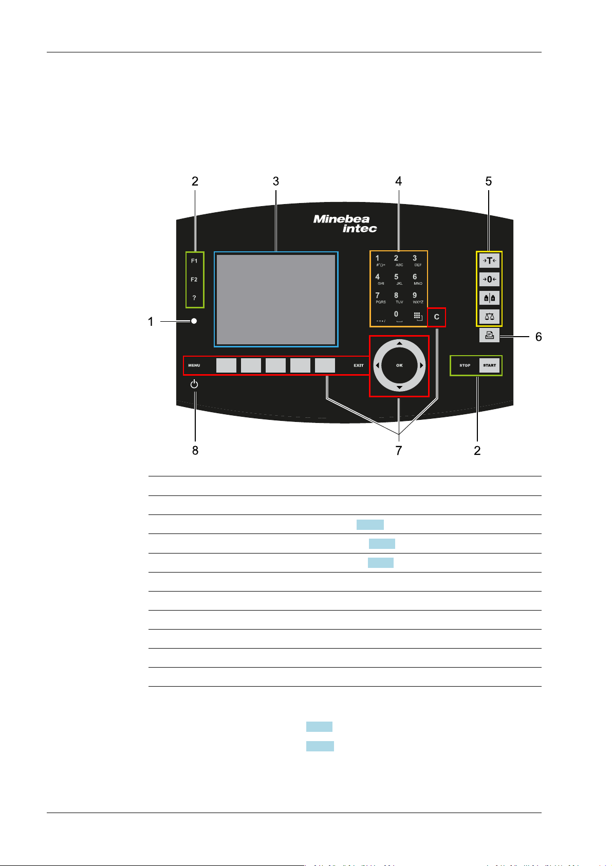
2.1 Display and control panel
2.1.1 Overview
No. Name
1 LED status display, see Chapter 2.1.2.2
3 5.7" TFT color display, see Chapter 2.1.2.1
2 Function keys
4 Alphanumeric keypad
5 Indicator keys
6 Application keys
7 Navigation/menu keys, incl. soft keys
8 On/o button
2.1.2 Display elements
- TFT screen display, see Chapter 2.1.2.1
- LED status display, see Chapter 2.1.2.2
Display elements
Operating elements, see Chapter 2.1.3.1
Minebea Intec EN-8
WP-A
Max 12200g d= 0.1g
Min 5g e= 1g
9
041
g
N
+
5g 12200g
Weighing point A @admin
Net=Gross
Net
Tare
<1115.[9] g>
<140.[9] g>
975.0 g
A
A
A
Set tare
7654
3
2
1
2 Commissioning Process Controller Maxxis 5 PR 5900
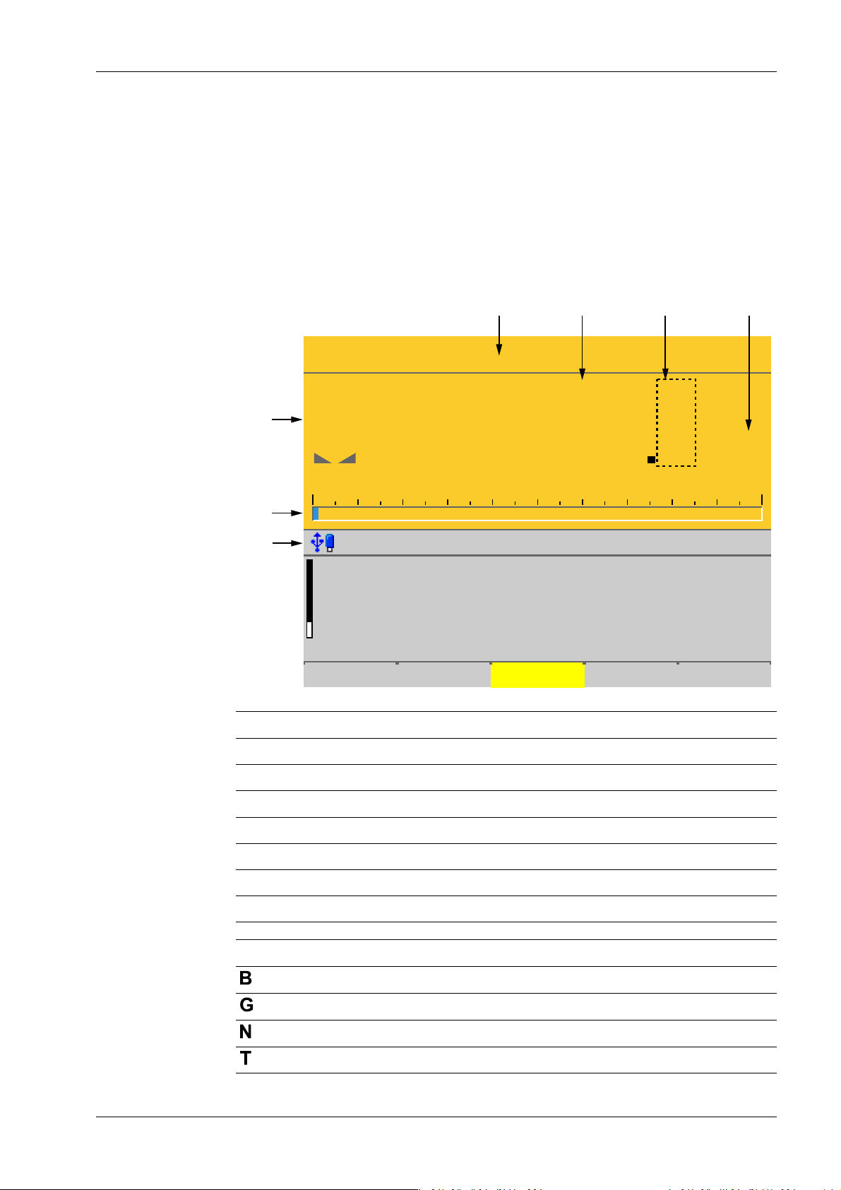
2.1.2.1 TFT user interface display
The TFT color graphics display can show weight values of up to 7 digits with decimal point
and plus or minus sign. The available mass units are t, kg, g, mg, lb, or oz.
The lb and oz units are not permitted for use in legal metrology in the EU and EEC.
Below the weight display, the currently displayed weight is shown in a bar graph that
indicates the percentage of the maximum capacity (Max). 0 is on the left, and 100% on the
right.
No. Description
1 Info line
2 Bar graph
3 Weight type/plus or minus sign/standstill
4 Status display
5 Weight value
6 Border around decimal place
7 Symbols/mass unit
Weight type/plus or minus sign Description
EN-9 Minebea Intec
Gross weight
Gross weight in NTEP or NSC mode
Net weight (Net = gross - tare)
Tare weight
Process Controller Maxxis 5 PR 5900 2 Commissioning
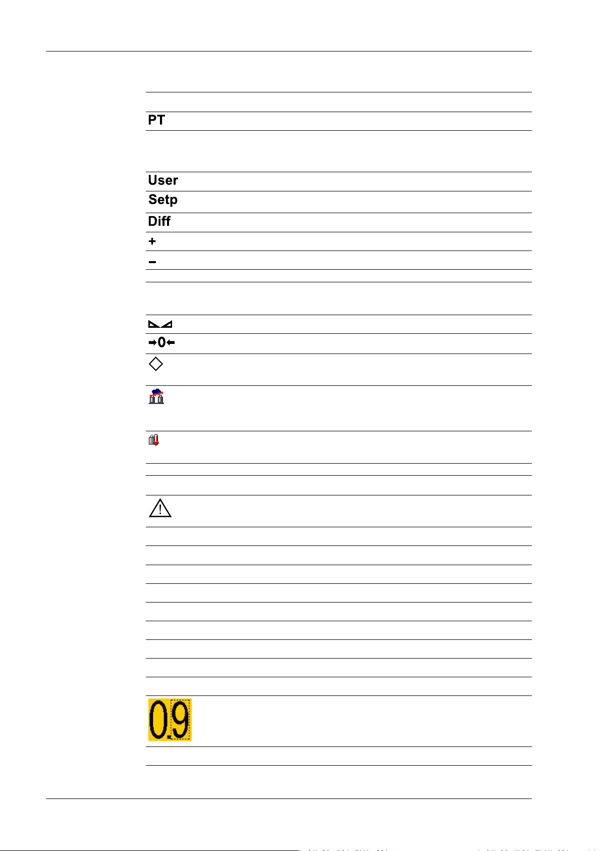
Weight type/plus or minus sign Description
Preset tare, not tared
No display - Test value
- Gross, not tared
Additional weight display, application-dependent
Additional weight display, application-dependent
Additional weight display, application-dependent
Positive value
Negative value
Standstill/zero/batching/monitoring
Symbols/mass unit Description
R1 Range 1
R2 Range 2
R3 Range 3
Description
Weight value standstill
The gross weight value is within ±¼ d of zero
Batching mode: ashes when batching is "stopped";
rapid ashing indicates "error status"
Pendeo load cells: Plausibility monitoring; the average deviation of the individual load cells is calculated
Pendeo load cells: Temperature monitoring; 1–n
load cells above or below permissible temperature
Value not permissible in legal metrology (e.g., 10x
resolution, deactivated load cell)
WP A Weighing point A
WP B Weighing point B
WP C Weighing point C
WP D Weighing point D
Max Maximum capacity (weighing range)
Min Minimum weight
Only if W&M is selected: Border around inadmissible
decimal place.
t, kg, g, mg, lb, oz These mass units are available.
Minebea Intec EN-10

2 Commissioning Process Controller Maxxis 5 PR 5900
Status icons in the info line
Icon Description
Remote control via VNC (Virtual Network Computing) is active.
- The clock battery is empty.
- The standby battery is empty.
The standby battery is too hot and is not charging.
If this does not go away, the ambient temperature
must be checked, see PR 5900 installation manual
under [Technical data] - [Environmental inuences]
- [Ambient conditions].
- An unsupported USB device is connected.
- The maximum current of i
= 200 mA has be-
max
en exceeded.
Check newly connected devices.
2.1.2.2 LED status display
Operating status Color LED status Description
Normal operation O
System ready (standby) Red Continuous illu-
Power interruption
<5 seconds
Power interruption
>5 seconds
USB stick was recognized and is operational.
Stick is in use and may not be removed.
Conict in the network settings of the IP address.
Interface (C1/CX1) was detected. However, there is
no connection to the operator terminal.
The display (screen) is switched
mination
o.
Red Slow ashing After 5 seconds, the device re-
turns to normal operation.
Red Fast ashing The device is running a data ba-
ckup. Once power is restored, the
device returns to normal operation (LED o).
After the data backup,
O The device switches o.
there is still a power interruption.
Power is restored O The device initiates a warm start,
see Chapter 2.2.2.
2.1.3 Operating elements
- Operation using the front-panel keys, see Chapter 2.1.3.1
EN-11 Minebea Intec

Process Controller Maxxis 5 PR 5900 2 Commissioning
- Operation using the soft keys, see Chapter 2.1.3.2
- Operation using the navigation keys, see Chapter 2.1.3.3
- Operation using the PC keys, see Chapter 2.1.3.4
- Operation using the VNC program, see Chapter 2.1.4
2.1.3.1 Operation using the front-panel keys
The following table shows the basic meanings of the symbols on the front-panel keys.
Depending on the applications, the keys may also have other meanings.
Indicator keys
Key Description
Set tare
The current gross weight is stored in the tare memory, provided that
- the weight value is stable.
- the device is not in error status.
(Function is dependent on conguration)
Sets gross weight to zero, provided that
- the weight value is stable.
- weight is within zero setting range.
(Function is dependent on conguration)
Display gross/tare weight
Pressing the key switches to the next weight (only with tared scale).
During calibration, pressing this key displays the weight for 5 seconds with
10x resolution.
Switching of display between the weighing points:
- WP‑A
- WP‑B
- WP‑C
- WP‑D
Application keys
Key Description
Starts an application-specic printout.
Navigation keys
Key Description
▲ Scroll up in the menu.
▼ Scroll down in the menu.
Minebea Intec EN-12
2 Commissioning Process Controller Maxxis 5 PR 5900
Key Description
◀ - Cursor to the left
- Selection
- Exit menu window.
▶ - Cursor to the right
- Selection
- Conrm input/selection.
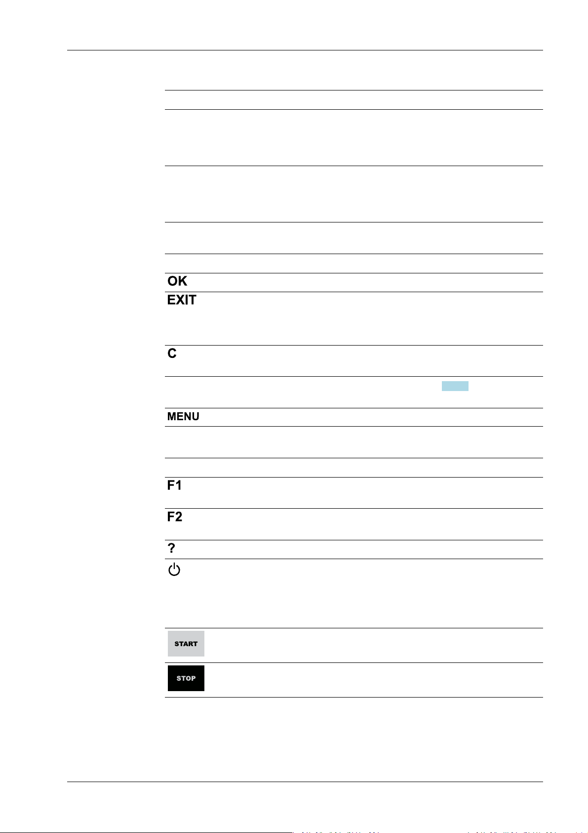
Menu keys
Key Description
Conrm input/selection.
- Cancel entry/selection (after a conrmation prompt) without saving
the change.
- Exit parameters/menu window.
Pressing the delete key deletes individual characters (within an entry) or
whole strings of characters.
Soft key 1 to5Select appropriate menu function, see also Chapter 2.1.3.2.
Switch to the operating menu.
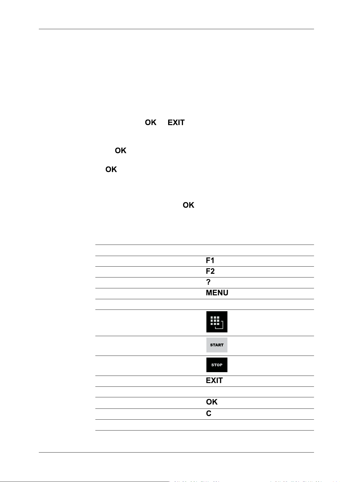
Function keys
Key Description
Assigned to a dened function (see system menu [System setup] - [Operating parameters]).
Assigned to a dened function (see system menu [System setup] - [Operating parameters]).
Displays the relevant help window.
- Turns o the display.
- Ignores all key presses.
- LED is red.
Pressing again will switch the display on again.
Starts an application-specic function.
Stops an application-specic function.
EN-13 Minebea Intec
.
Process Controller Maxxis 5 PR 5900 2 Commissioning
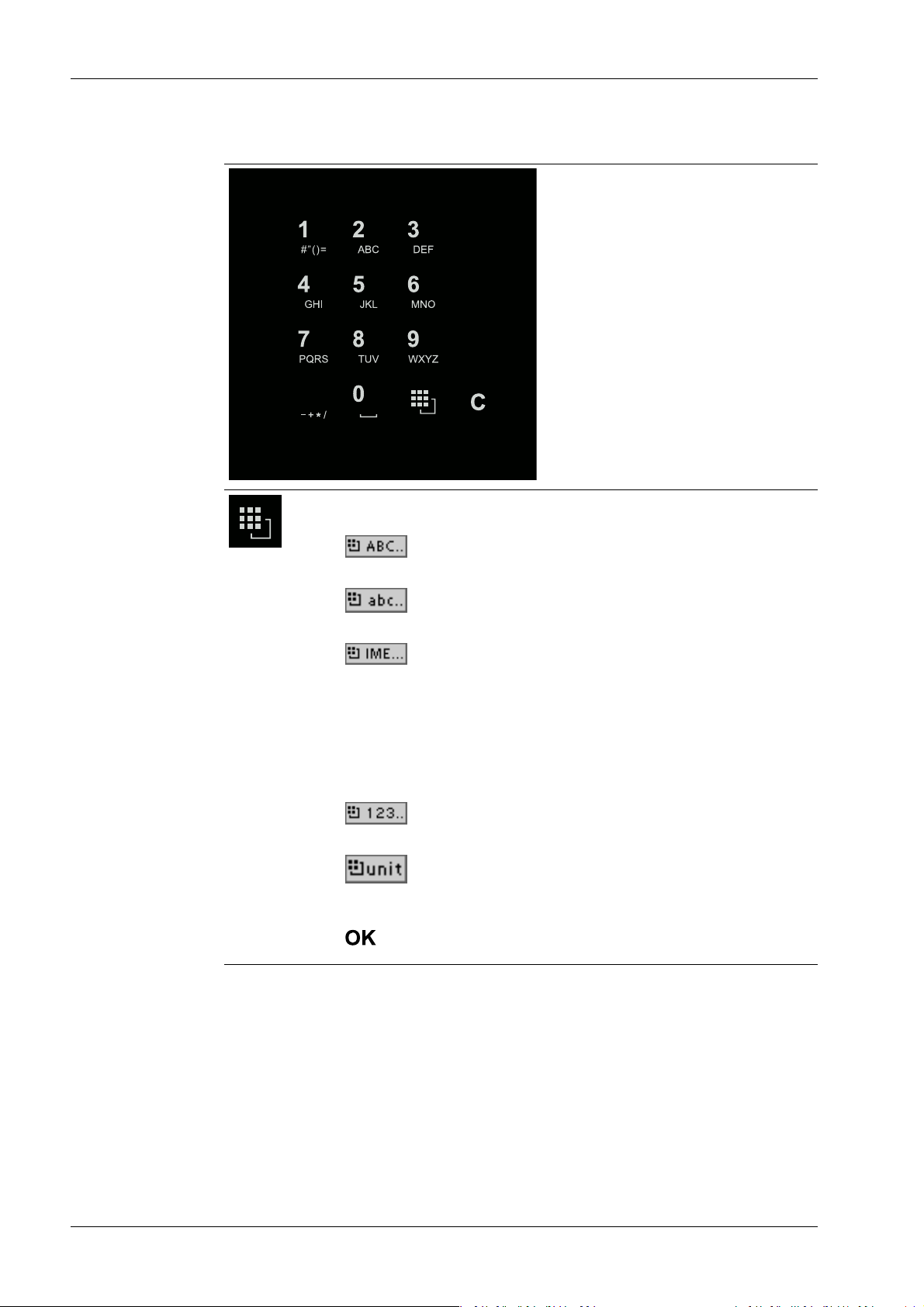
Alphanumeric keypad
Toggle key
Pressing switches between the following functions:
-
Uppercase letters
-
Lowercase letters
-
Pinyin
When Chinese has been selected or set under [Operating parameters]
- [Input method].
- Hepburn
When Japanese has been selected or set under [Operating parameters] - [Input method].
-
Numbers
-
Units
Select the unit using the cursor keys ▲/▼ and conrm using the key
.
Minebea Intec EN-14
2 Commissioning Process Controller Maxxis 5 PR 5900
Input without the character table
Pressing once displays the corresponding rst character, e.g., "A", at the
cursor position. After pressing twice, "B" is displayed at the cursor position
and after pressing three times, "C" is displayed.
Press the cursor keys ▼/▲ to nish entering a character or wait approx.
2 seconds.
If only numeric values are required for input, letters are not enabled.
Press the cursor key ◀ within an entry to return to the previous character.
Press the cursor key ▶ within an entry to select the next character.
Within an entry, pressing the delete key deletes the character to the left
of the cursor.
Outside of an input, pressing the delete key deletes the whole string of
characters.
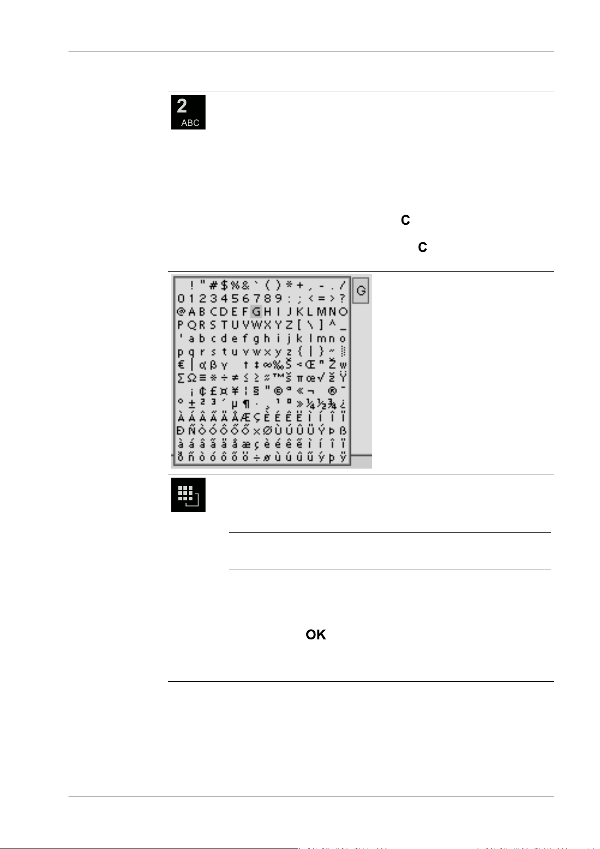
Input with the character table
Double-clicking on the key displays the character table.
Only characters authorized for this input are displayed.
Note:
The switching function is turned o.
Procedure:
- Highlight the desired character with the cursor.
- The selected character is shown magnied in the eld at the top right.
- Press the key to enter the character in the input eld.
- Another double-click on the toggle key and other characters can be in-
put as described previously.
EN-15 Minebea Intec
WP-A
Max 3000g d= 0.1g
+
A
B
C
Enter user name and password
User name
Password
********
WP-A
Max 3000g d= 0.1g
+
Enter user name and password
User name
Password
********
ABC..
Default Save
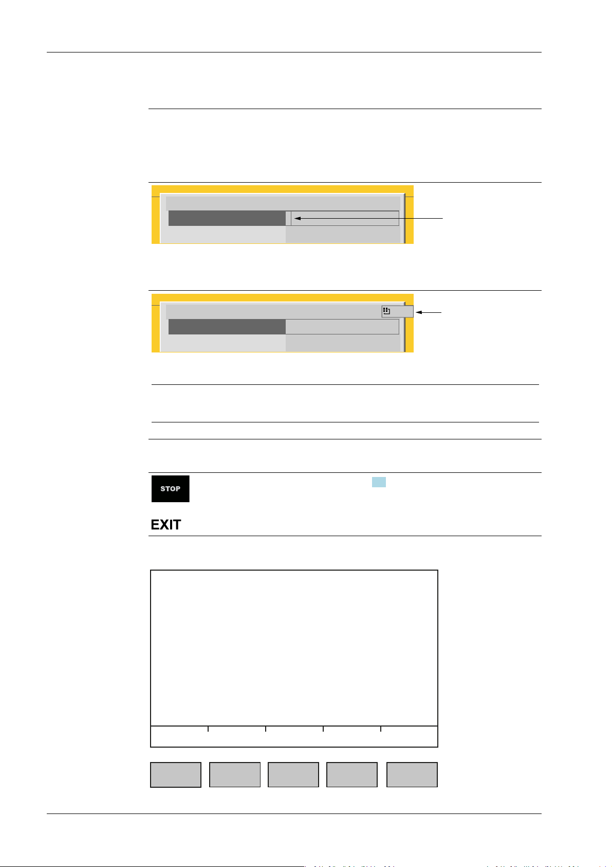
Process Controller Maxxis 5 PR 5900 2 Commissioning
Input eld
In principle:
If alphanumeric characters are already present in the input eld of the selected line, they
will be completely overwritten after immediate entry.
If alphanumeric characters are already present in the input eld of the selected line, you
can press the cursor key ▶ to select the characters to be overwritten and overwrite them.
In front of the input eld it is indicated whether numeric and/or alphabetic characters
can be entered (see arrow).
Switch to the input eld using the cursor key ▶.
The respective options are displayed (see arrow).
Note:
The character table is turned o.
Keyboard shortcuts
+
2.1.3.2 Operation using softkeys
Trigger a cold start, see also Chapter 4.3.
Minebea Intec EN-16
2 Commissioning Process Controller Maxxis 5 PR 5900
The functions of the ve softkeys below the graphic display are indicated in the
bottommost text line of the display. Softkey functions shown in gray cannot be selected
at the active menu level or with the current access privileges.
In the descriptions of operating sequences which entail the use of softkeys, the softkey
function to be selected is shown in square brackets; the softkey symbol is not displayed;
example: [Save].
2.1.3.3 Navigation key operation Menu
The cursor keys, the and keys are used to navigate through the menus.
Parameters
Use the ▼/▲ cursor keys to select the individual parameters.
Use the key to conrm the selection.
The required values | texts are entered via the alphanumeric keys.
The key is used to check the ☑ box.
If the list of parameters is long, a vertical bar graph on the left (black and gray) shows
which part of the list is displayed.
An existing selection list is indicated by an arrow ▶ following it.
The parameter is selected using the key.
2.1.3.4 Operation via PC keys
The device can also be operated using a PC keyboard. The corresponding key assignment
is shown in the table below:
PC keyboard Front keypad
F1
F2
F3
F4
F5…F9 Softkey 1…5
F10
F11
F12
ESC
Cursor keys: ↑, ↓, ←, → ▲, ▼, ◀, ▶
Enter key: ↵
Backspace key: ←
Numeric keypad Alphanumeric keypad
EN-17 Minebea Intec

Process Controller Maxxis 5 PR 5900 2 Commissioning
2.1.4 Display and operation using VNC client
The display and operating elements are described in the following chapters:
- Overview of front of device, see Chapter 2.1.1.
- User interface of TFT screen, see Chapter 2.1.2.1.
- Operation using the front-panel keys, see Chapter 2.1.3.1.
Setting up the VNC client, see Chapter 2.9.5.
2.2 Data security and data storage
The calibration data and parameters of the internal weighing electronics system are saved
to the EAROM (Electrically Alterable ROM) on the weighing electronics board. Additional
write protection is provided for calibration data and parameters (see Chapter 2.7.2).
The event logger is saved to the SPI ash (Serial Peripheral Interface ash) memory.
The FlashPROM contains:
- BIOS
- Firmware
- Application Program
- Alibi memory
- XML conguration les (for user management, system setup, calibration and
The backups are stored on the SD card (Secure Digital card) (see also PR 5900 installation
manual under [Hardware construction]- [Main board]- [SD card slot] ).
2.2.1 Power failure
The entire content of the working memory is stored to a NAND ash memory and remains
there permanently when the power is interrupted or the device is disconnected from the
power.
The SD card and the USB stick are buered by a battery.
If a HUB (splitter) is inserted into the USB slot and turned o, the connection between the
USB stick and battery is broken.
2.2.2 Warm start
When power is restored, all data are reloaded from the NAND ash memory to the
working memory and the device is restored to the operating status before the
interruption. Filling programs are stopped/started depending on user settings.
2.2.3 Cold start
application data)
A cold start is performed if the device nds no saved data with which the last operating
state can be restored.
A cold start can have various causes:
- The battery has not been charged properly or is faulty, and it was not possible to save
all the data when the power was disconnected.
- The device was restarted using the STOP+EXIT keys, see Chapter 2.2.3.1.
- The reset key was pressed, see Chapter 2.2.3.2
Minebea Intec EN-18

2 Commissioning Process Controller Maxxis 5 PR 5900
- The STOP key was held down during startup and cold start was then selected, see
Chapter 3.10.
If available, the database from the last backup is restored after a cold start.
2.2.3.1 STOP+EXIT buttons Pressing STOP+EXIT simultaneously (see Chapter 4.3) initiates a cold start of the device:
- The settings are retained.
- The database is initialized.
- The device automatically searches for an existing database on the SD card and asks
whether this should be loaded.
- The application must be restarted.
Note:
If [Operating]- [System setup]- [Operating parameters]- [Cold start with STOP+EXIT][disabled] is selected in the menu, the device cannot be restarted with STOP+EXIT.
2.2.3.2 Reset key
Briey pressing (< 1 sec.) the reset key (see PR 5900 installation manual under [Process
controller]- [Housing]- [Housing dimensions]- [Control cabinet housing] ) initiates a cold
start of the device:
- The LED ashes once.
- The settings are retained.
- The database is initialized.
- The device automatically searches for an existing database on the SD card and asks
whether this should be loaded.
- The application must be restarted.
2.3 Switching on the device
Note:
The following steps must be followed when connecting the device to mains voltage for
the rst time:
- Set the date and time, see Chapter 4.2.
- Set up the network (only necessary if the device is to be used or congured in the
network), see Chapter 4.4.
The device can be set up as follows:
- Via keys on the front of the device, see Chapter 2.1.3.1.
- Via an external PC keyboard, see Chapter 2.1.3.4.
- Via a notebook/PC using the VNC software (included on the CD), see Chapter 2.9.5.
- Via a notebook/PC using an Internet browser, see Chapter 2.9.6.
EN-19 Minebea Intec

WP-A
Max 3000g d= 0.1g
00
+
g
0g 3000g
22.08.2012 15:20:46
Login
Process Controller Maxxis 5 PR 5900 2 Commissioning
When the device is powered up, the following appears:
Checking…
Booting…
Restore…
No signal Error message: if no load cells are connected, see also Chapter 9.1.
No values from
scale
Scale not ready Error message: if no load cells or no scale is connected (see also Chap-
The weight display appears.
The device is booting up.
Error message: if there is no communication with the xBPI scale (see
also Chapter 9.2).
Error message: unable to read weight values from the ADC (analog-digital converter); see also Chapter 9.1.
ter 9.1).
2.4 Switching o the device
Switching o the device, see Chapter 6.8.
2.5 Device warm-up time
A warm-up time of 30 minutes for the device is required before calibration is started.
2.6 Operating via front-panel keys/PC keyboard
The following options are possible:
- Via keys on the front of the device, see Chapter 2.1.3.1.
- Via an external PC keyboard (USB connection), see Chapter 2.1.3.4.
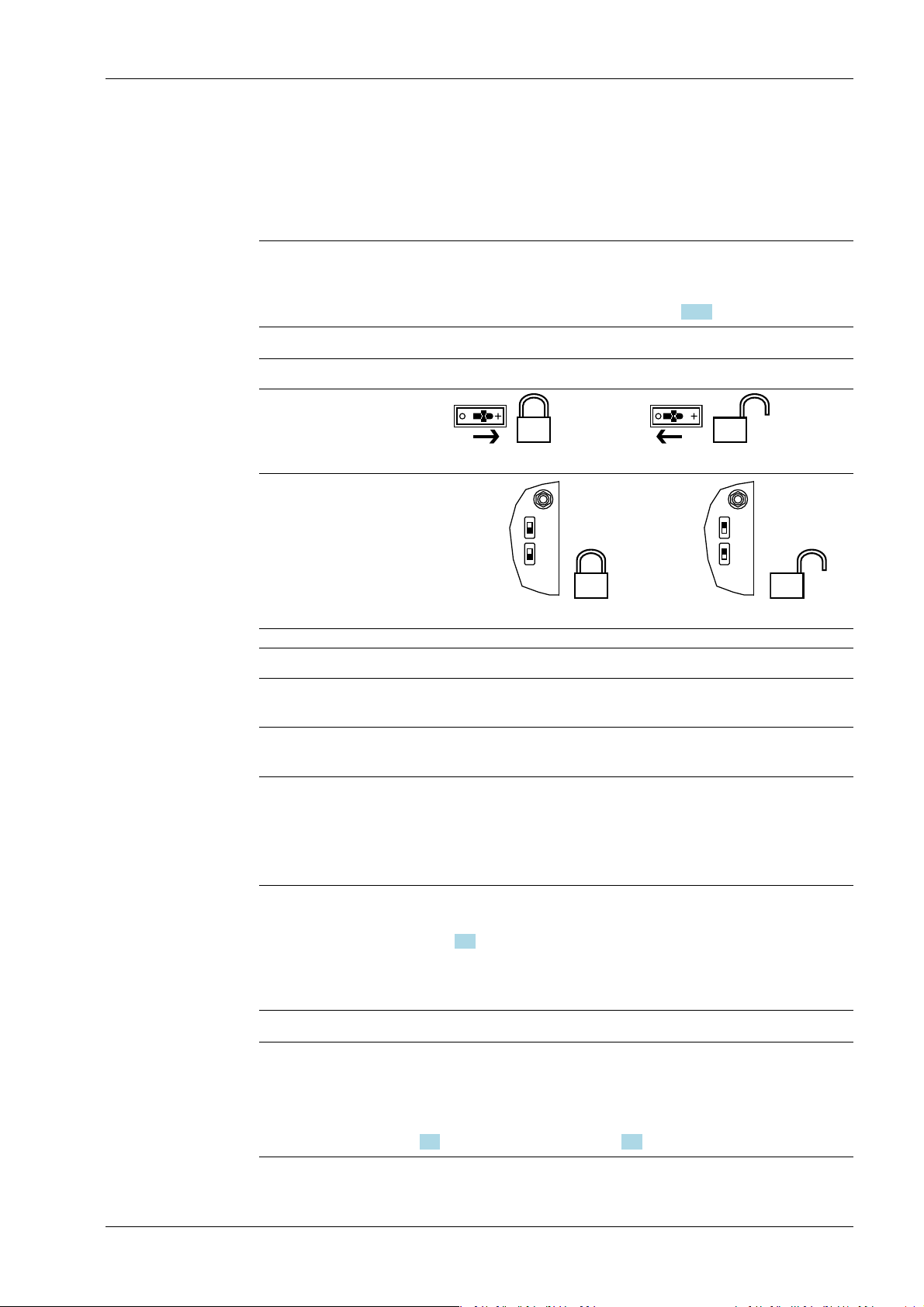
2.7 Overwrite protection
2.7.1 CAL switch
Overwrite protection can be activated using the CAL switch to prevent unauthorized
access to or overwriting of the calibration data/parameters.
The device can have up to 4 CAL switches. CAL switches 1 and 2 are located on the main
board and are accessible via two holes in the housing.
Minebea Intec EN-20
CAL 2
CAL 1
CAL 2
CAL 1
2 Commissioning Process Controller Maxxis 5 PR 5900
Depending on the model, CAL switches A and B may also be present. They are located on
the corresponding weighing electronics board (see PR 5900 installation manual). These
switches can only be accessed by removing the device housing.
The exact function of individual switches is listed in the table below.
Note:
In general, we recommend activating the overwrite protection features via the software
after calibration to prevent overwriting/data loss (see Chapter 2.7.2).
Write protection active Write protection inactive
CAL switches A and B
closed opened
CAL switches 1 and 2
closed
opened
CAL switch Meaning of "Write Protection Active"
A Prevents the calibration data/parameters of weighing electronics A
from being changed
B Prevents the calibration data/parameters of weighing electronics B
from being changed
1 The following changes are prevented:
- Allocation of weighing electronics to logical weighing points
- Calibration data and parameters of other weighing points
- Alibi settings
2 The following is prevented:
- Loading/ashing of rmware and BIOS to the device, see also
Chapter 6.9
- Changing of license settings
This CAL switch is sealed for use in legal metrology.
Note:
Changing means:
Changing by entering data into the input elds as well as changing via the functions
[Restore] (see Chapter 6.2) and [Import] (see Chapter 6.4).
EN-21 Minebea Intec
WP-A
Max 3000g d= 0.1g
00
+
g
Weighing points @admin
Weighing point A
Weighing point B
Weighing point C
Weighing point D
Internal weighing point
Internal weighing point
xBPI scale
Pendeo Process
Parameters Calib Units
CAL switch A is closed.
WP-A
Max 3000g d= 0.1g
00
+
g
Calibration (CAL switch is closed) @admin
Max
Scale interval
Dead load at
Max at
calibrated at
Sensitivity
3000.0 g
0.1 g
mV/V
mV/V
mV/V
µV/d
0.040800
1.177298
0.987557
0.470919
30000 d
1 d
103.966 g
3000.000 g
2516.5 g
98.11 cnt/d
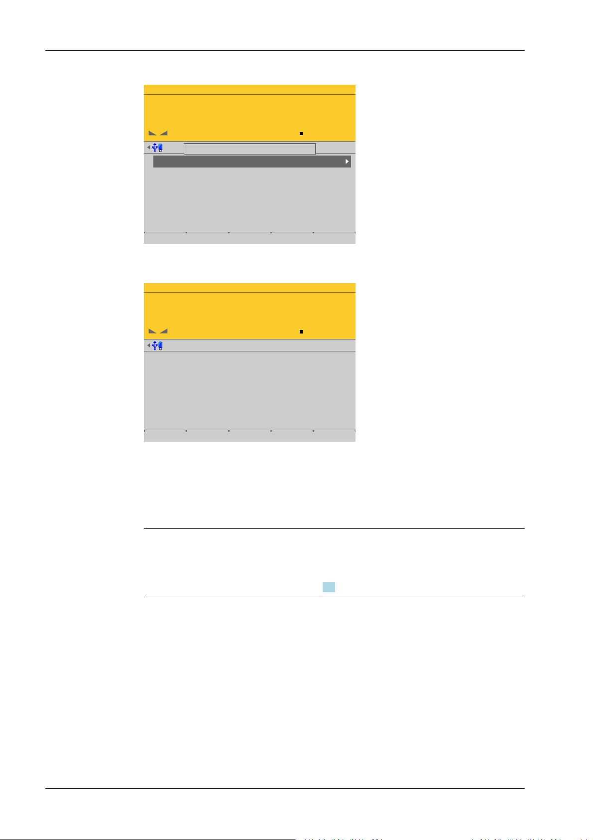
Process Controller Maxxis 5 PR 5900 2 Commissioning
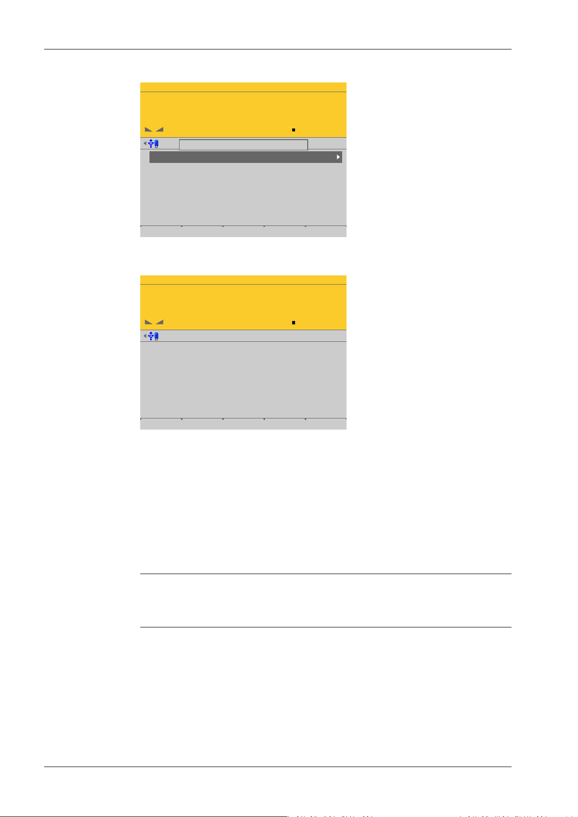
When a CAL switch is closed, a tool tip is displayed in the menu [Weighing points].
The data under the soft keys [Parameters], [Calibration], and [Units] is displayed only.
2.7.2 Software
Minebea Intec EN-22
Example of calibration data.
Overwrite protection can be activated via software to prevent unauthorized access to or
overwriting of the calibration data/parameters.
Note:
A unique check number is created every time a calibration or changed parameters are
saved. This can be viewed in the menu [Operating] - [System information] - [Show
calibration check numbers] (see Chapter 5.7) and may also be written on the W&M label.
Accessible via MENU – [Operating] - [System setup] - [Weighing points] - [Weighing
point x] - [Parameters] - [Settings locked].
WP-A
Max 3000g d= 0.1g
00
g
Weighing points @admin
Weighing point A
Weighing point B
Weighing point C
Weighing point D
Internal weighing point
Pendeo Truck
xBPI scale
User scale
Parameters Calib Units
WP-A
Max 3000g d= 0.1g
00
g
Weighing points @admin
Settings locked
W&M
Measurement time
Digital filter
Cutoff frequency
External load cell supply
none
160 ms
aperiodic
2.00 Hz
below or equal 8 V
Default Save
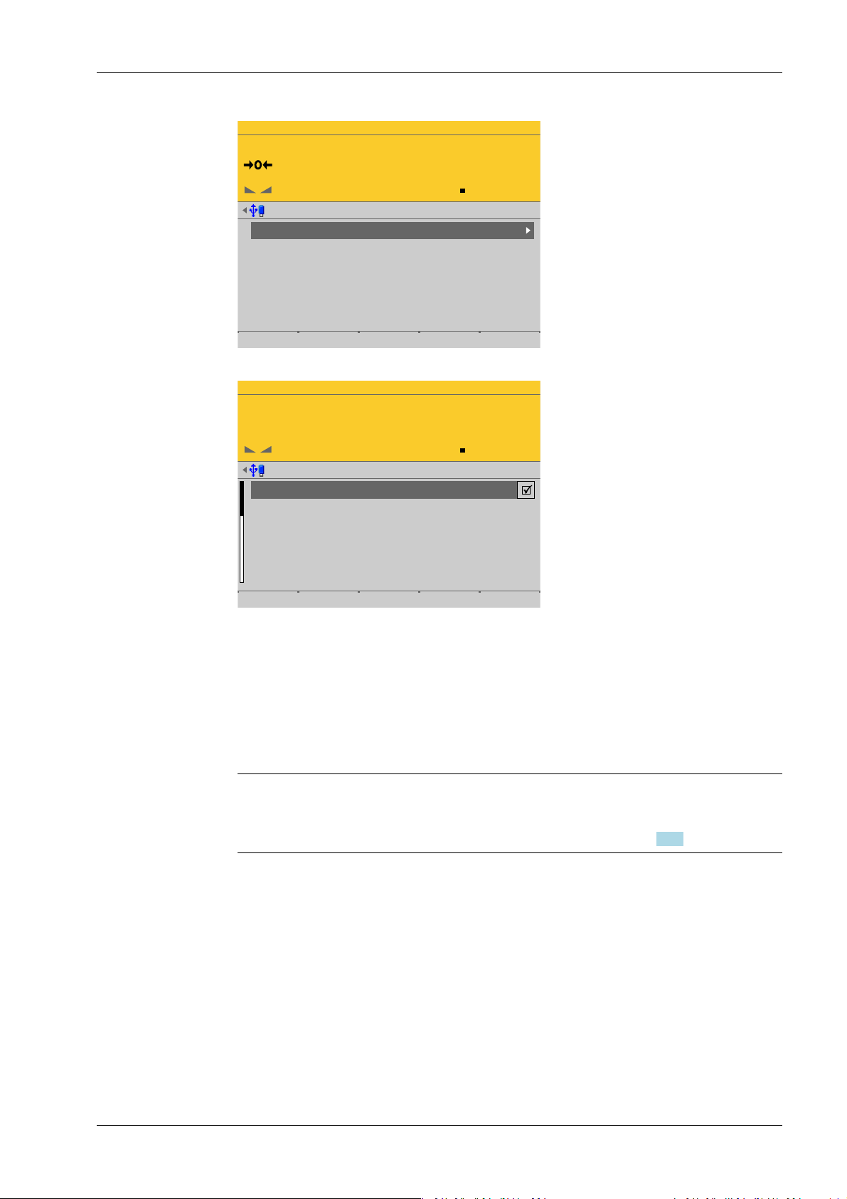
2 Commissioning Process Controller Maxxis 5 PR 5900
Each weighing point has a [Settings locked] parameter in the menu item [Parameters].
EN-23 Minebea Intec
If this parameter is set for the weighing point,
- the calibration data and parameters of the corresponding weighing point and the
weighing point allocation are only viewed as if the corresponding CAL switch were
closed.
- Only the [Settings locked] parameter can be changed.
- [Restoring]/[Importing] a weighing point is disabled.
Note:
If [Settings locked] and [W&M] have been selected for at least one weighing point, this
has the same eect as a closed CAL 1 and CAL 2 switch, see Chapter 2.7.1.
WP-A
Max 3000g d= 0.1g
00
+
g
Weighing points @admin
Weighing point A
Weighing point B
Weighing point C
Weighing point D
Internal weighing point
Pendeo Truck
xBPI scale
User scale
Parameters Calib Units
'Settings locked' is set
WP-A
Max 3000g d= 0.1g
00
+
g
Calibration (Settings locked) @admin
Max
Scale interval
Dead load at
Max at
calibrated at
Sensitivity
3000.0 g
0.1 g
mV/V
mV/V
mV/V
µV/d
0.040346
1.177703
0.987896
0.471081
30000 d
1 d
102.774 g
3000.000 g
2516.5 g
98.14 cnt/d
Process Controller Maxxis 5 PR 5900 2 Commissioning
If [Settings locked] is active, a tool tip appears in the menu [Weighing points].
The data under the soft keys [Parameters], [Calibration], and [Units] is displayed only.
2.8 Switching on blackbox device
2.8.1 Connecting to remote terminal PR 5900/6x, ../7x
2.8.2 Network settings
Minebea Intec EN-24
Example of calibration data.
The blackbox device can be operated with the PR 5900/6x, ../7x remote terminal.
There are no setting options for the connection to the remote terminal.
If the installation has been carried out correctly, the connection to the remote terminal is
automatically established.
Note:
For information on installation and switching on the remote terminal, see PR 5900/6x,
../7x instrument manual.
The device has the following factory settings:
- Device IP address (default): 192.168.1.2
- Subnet mask (default): 255.255.255.0
2 Commissioning Process Controller Maxxis 5 PR 5900
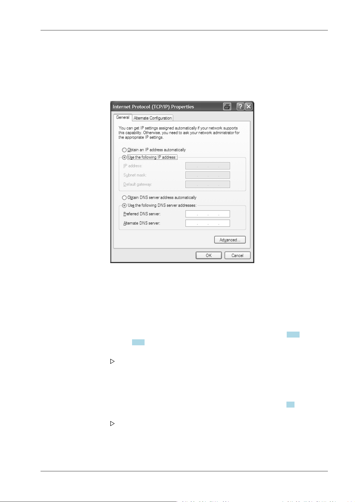
2.8.3 Connecting to notebook/PC
1. Do not establish a connection between the blackbox device and the network to begin
with!
2. Note down the notebook/PC network settings.
3. Disconnect the notebook/PC from the network.
4. In the notebook/PC, click the second line [Use the following IP address] (DHCP is now
deactivated).
5. Enter the xed IP address "192.168.1.2" and the subnet mask "255.255.255.0" and
save.
6. Directly connect the notebook/PC and blackbox device with a network cable (without
a splitter).
7. Open a web (Internet) browser (e.g. Microsoft Internet Explorer, Mozilla Firefox, etc.).
8. Enter the IP address of the blackbox device: 192.168.1.2, see Chapter 2.9.5 or
Chapter 2.9.6.
9. Conrm the entry.
The device name entered under [Host name] appears under the header in
brackets.
10. Note down the host name (here: "PR5900-27FF07").
11. In the menu [Operating]- [System setup]- [Network parameters] modify the network
address of the blackbox device to the required address or activate DHCP according to
the responsible system administrator's instructions; see also Chapter 4.4.
12. Save the settings.
The blackbox device sets itself to the new address.
This means that the connection to the notebook/PC is lost.
13. Disconnect the cable connection between the notebook/PC and blackbox device.
14. Connect the blackbox device to the network using a network cable.
EN-25 Minebea Intec

Process Controller Maxxis 5 PR 5900 2 Commissioning
15. Re-enter the network settings (as noted previously) on the notebook/PC.
The blackbox device will now be available on the network under the new address
and ready for operation.
Note:
Resetting the network settings (see also Chapter 2.8.2) by:
- Holding down the reset button for > 5 s, see Chapter 2.9.4.
- Selecting and conrming the menu [Operating]- [System setup]- [Network
parameters]- [Default] .
2.9 Operating via a notebook/PC
The following options are possible:
- Via VNC Viewer (on the enclosed CD-ROM), see Chapter 2.9.5.
- Via the internet browser, see Chapter 2.9.6.
Requirement:
The Java application must be supported by the web browser.
2.9.1 Finding and connecting the device automatically in the network
If the DHCP server is active in the network, the connected device (if activated in the menu
[Operating] - [Default conguration] - [Network parameters] - [use DHCP]) is
automatically assigned an IP address.
On the notebook/PC, the host names of the connected devices in the network are listed
under [Network].
Double-click the host name to open the device page in the web browser. The IP address is
displayed on the bottom right.
Note:
If the web browser supports the Java application, the device can be operated via[remote
conguration (VNC).]
If the web browser does not support the Java application, the menu items will be
inaccessible (grayed out).
2.9.2 Finding and connecting a device with a notebook/PC
If the device is connected to a notebook/PC via a point-to-point connection, an IP
address is negotiated via function "AutoIP". This can take up to 2 minutes!
NOTICE
When the IT/DHCP network cable is temporarily connected between the notebook/
PC and a device, the DHCP server is lost and the notebook/PC returns to the auto-IP
address within approx. two minutes!
Reason: The DHCP server/client relationship is checked cyclically at 23-minute
intervals.
Minebea Intec EN-26

2 Commissioning Process Controller Maxxis 5 PR 5900
1. On the notebook/PC, set the LAN local and Internet Protocol properties to "Obtain an
IP address automatically" depending on the operating system.
2. On the device, under MENU - [Default conguration] - [Network parameters] activate
the "Use DHCP" parameter (factory/default settings).
The DHCP devices nd each other because they fall into an "auto-IP address" in
the range 169.254.0.1169.254.255.254 with the associated auto-subnet mask
255.255.0.0 after a cyclical automatic DHCP server search run due to time
overow (23 minutes).
Example:
If the search time is exceeded (because there is "no server found"), the PR 5900 is
assigned to an IP address automatically (e.g. 169.254.0.123). The same applies to
the notebook or PC (e.g. 169.254.0.54).
These IP addresses are dierent on both sides:
- equal regarding the rst 2 octets of the IP address (e.g. network ID 169.254.)
- dierent in the last 2 octets of the IP address (e.g. host ID 0.123.)
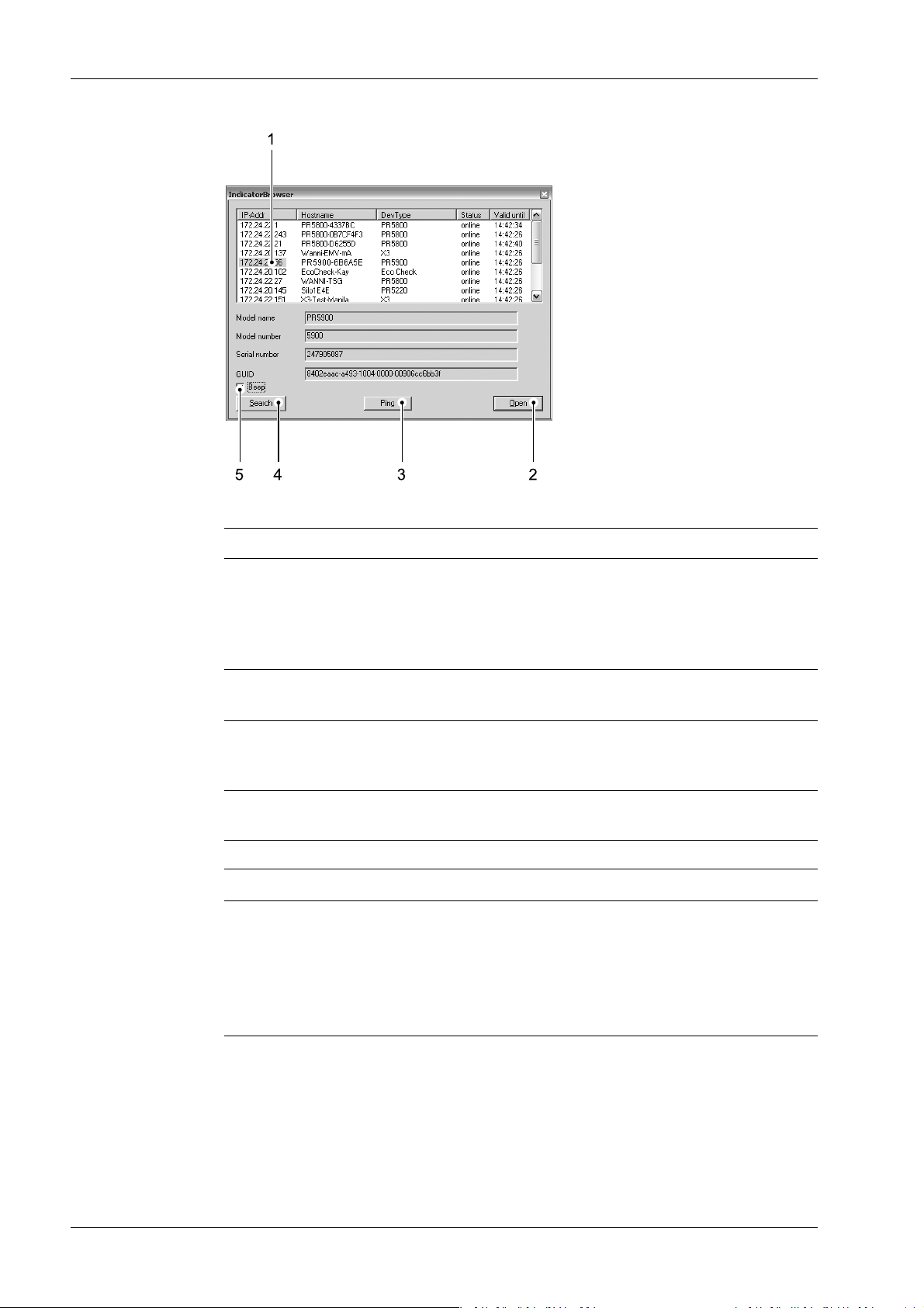
2.9.3 Searching the device in the network with "IndicatorBrowser"
The IP address can be found out using the "IndicatorBrowser" application (supplied on
CD-ROM) and via the "host name" of the device.
The "host name" is composed of the device name and the last 3 bytes of the MAC ID. A
label with the complete MAC ID is located on the outside of the device.
Host name: PR5900-6B6A5E
For this, the program must be installed and started on a notebook/PC.
EN-27 Minebea Intec
Process Controller Maxxis 5 PR 5900 2 Commissioning
Legend
No. Description
1 The program searches within the current network ID, e.g. 169.254. and 172.24.,
on all available network adapters in the PC (several possible/recommended,
e.g. LAN global/LAN local)
Result:
List of all connected devices with status: search??? – online - byebye – lost???
2 Click the button to open the "standard" Internet Browser, e.g. Microsoft Inter-
net Explorer, directly with the marked IP‑address.
3 Click the button to localize the associated device.
Short-term visual feedback from the device:
Regular running light in LED 1, 2, 3.
4 Click the button to re-start the network search run.
Waiting 2…3 minutes is essential!
5 Acoustic signal for each device that was detected as "online."
Note:
If the browser window remains empty after the minimum wait time, or if the expected
device is not listed, the network ID of the local notebook/PC must be checked and
changed, if necessary.
Only certain Minebea Intec devices are supported by the "indicator browser"!
Minebea Intec EN-28
 Loading...