

Page 1

Instrument Manual
Sartorius Mechatronics T&H GmbH, Meiendorfer Str. 205, 22145 Hamburg, Germany
Tel: +49.40.67960.303 Fax: +49.40.67960.383
Process Controller Maxxis 4
PR 5500
Instrument Manual 9499 050 55000 Edition 2 24.07.2015
for PR 5500 Release 2.20
Page 2

Please note
Any information in this document is subject to change without notice and does not represent a commitment
on the part of SARTORIUS INTEC unless legally prescribed. This product should be operated only by trained and
qualified personnel. In correspondence concerning this product the type, name and release number as well as
all license numbers in relation to the product have to be quoted.
Important
This product is partly copyrighted. It may not be modified or copied and may not be used without purchasing
or written authority from the copyright owner (SARTORIUS INTEC). By using this product, you agree to be
bound by the terms stated herein.
Page 3

PR 5500 Instrument Manual Table of Contents
Table of Contents
1 Introduction.........................................................................................................................................................................1
2 Safety Information ............................................................................................................................................................. 2
2.1 Electrical Protective Class............................................................................................................................................................................2
2.2 Intended Use ....................................................................................................................................................................................................2
2.3 Initial Inspection ............................................................................................................................................................................................2
2.4 Before Commissioning ..................................................................................................................................................................................3
2.4.1 Installation ............................................................................................................................................................................................3
2.4.2 Opening the Instrument ...................................................................................................................................................................4
2.4.3 Mains Connection and Protective Grounding Conductor for PR 5500 .............................................................................4
2.5 RF Interference Suppression .......................................................................................................................................................................6
2.6 Failure and Excessive Stress ........................................................................................................................................................................6
2.7 Important Note ...............................................................................................................................................................................................6
2.8 Repairs and Maintenance ............................................................................................................................................................................6
2.8.1 Static Sensitive Components ...........................................................................................................................................................6
2.8.2 Replacing Fuses ...................................................................................................................................................................................6
3 Process Controller ............................................................................................................................................................... 7
3.1 General Information .....................................................................................................................................................................................7
3.2 Overview of the Instrument .......................................................................................................................................................................7
3.3 Housing .............................................................................................................................................................................................................9
3.3.1 Housing dimensions ...........................................................................................................................................................................9
3.3.2 Housing Dimensions with Strain Relief and Reinforcing frame ....................................................................................... 10
3.3.3 Control Panel Cut-Out ................................................................................................................................................................... 11
3.4 Display and Control Panel ........................................................................................................................................................................ 12
3.4.1 Overview ............................................................................................................................................................................................. 12
3.4.2 Display ................................................................................................................................................................................................. 13
3.4.3 Operating Elements ......................................................................................................................................................................... 15
3.4.4 Operation using the VNC Program ............................................................................................................................................. 19
3.5 Overview of Connections ......................................................................................................................................................................... 20
3.5.1 Plug-in Cards ..................................................................................................................................................................................... 21
3.5.2 Application Licenses ........................................................................................................................................................................ 23
3.6 Instrument Versions ................................................................................................................................................................................... 24
3.6.1 Combinatorics for the Options .................................................................................................................................................... 24
Sartorius EN-I
Page 4

Table of Contents PR 5500 Instrument Manual
4 Device Installation ............................................................................................................................................................27
4.1 General Information .................................................................................................................................................................................. 27
4.2 Mechanical Preparation ............................................................................................................................................................................ 28
4.3 Hardware Construction ............................................................................................................................................................................. 30
4.3.1 Main Board ........................................................................................................................................................................................ 30
4.3.2 Network Port ..................................................................................................................................................................................... 31
4.3.3 USB Connection ............................................................................................................................................................................... 32
4.3.4 SD Card Slot ....................................................................................................................................................................................... 36
4.3.5 RS-232 Interface (built-in) ........................................................................................................................................................... 37
4.4 Accessories .................................................................................................................................................................................................... 42
4.4.1 PR 5500/04 2x RS-485 Interface ................................................................................................................................................ 42
4.4.2 PR 5500/32 2x RS-232 Interface ................................................................................................................................................ 52
4.4.3 PR 5500/07 Analog Inputs and Outputs ................................................................................................................................... 57
4.4.4 PR 5500/10 Weighing Electronics Board .................................................................................................................................. 59
4.4.5 PR 5500/12 Digital Inputs and Outputs ................................................................................................................................... 69
4.4.6 PR 5500/13 Digital Inputs and Outputs ................................................................................................................................... 76
4.4.7 PR 5500/17 Digital Inputs and Outputs ................................................................................................................................... 83
4.4.8 PR 1721/61 ProfiBus-DP................................................................................................................................................................ 91
4.4.9 PR 1721/64 DeviceNet ................................................................................................................................................................... 94
4.4.10 PR 1721/65 CC-Link ........................................................................................................................................................................ 98
4.4.11 PR 1721/66 ProfiNet I/O .............................................................................................................................................................. 101
4.4.12 PR 1721/57 EtherNet-IP .............................................................................................................................................................. 104
5 Commissioning ............................................................................................................................................................... 107
5.1 Power Failure/Data Protection/Warm Start/Cold Start ................................................................................................................107
5.1.1 General Information .....................................................................................................................................................................107
5.1.2 Power Failure ...................................................................................................................................................................................107
5.1.3 Warm Start ......................................................................................................................................................................................107
5.1.4 Cold Start .........................................................................................................................................................................................108
5.1.5 Overwrite Protection ....................................................................................................................................................................109
5.2 Switching on the Device ......................................................................................................................................................................... 111
5.3 Switching off the Device ........................................................................................................................................................................ 113
5.4 Warm-up Time ........................................................................................................................................................................................... 113
5.5 Configuring and Calibrating via the Front Keys/PC Keyboard ................................................................................................... 113
5.6 Configuring and Calibrating via a Notebook/PC ............................................................................................................................114
5.6.1 Connecting the Device to the Network and Determining the IP Address ................................................................... 114
5.6.2 Activating the ‘DHCP’ Network ................................................................................................................................................. 116
5.6.3 Searching for Devices in the Network using ‘IndicatorBrowser’ .................................................................................... 118
5.6.4 Operation using the VNC Client Program .............................................................................................................................. 119
5.6.5 Operation via a Web Browser .................................................................................................................................................... 120
5.6.6 Resetting Network ......................................................................................................................................................................... 123
5.7 Help Function ............................................................................................................................................................................................. 124
5.8 Selecting the Operating Language ...................................................................................................................................................... 124
EN-II Sartorius
Page 5

PR 5500 Instrument Manual Table of Contents
5.9 User Management.....................................................................................................................................................................................125
5.9.1 General Information .....................................................................................................................................................................125
5.9.2 Activating User Management .................................................................................................................................................... 125
5.9.3 Deactivating User Management................................................................................................................................................133
5.9.4 User Login/Logout..........................................................................................................................................................................134
5.10 System Menu .............................................................................................................................................................................................. 135
5.10.1 System Setup: Connected Devices ............................................................................................................................................135
5.10.2 System setup: Date & Time ......................................................................................................................................................... 136
5.10.3 System setup: Operating parameters ...................................................................................................................................... 137
5.10.4 System setup: Network parameters ......................................................................................................................................... 138
5.10.5 System setup: Network share connections ............................................................................................................................ 139
5.10.6 System setup: Fieldbus parameters .......................................................................................................................................... 140
5.10.7 System setup: Weighing point – Weighing point A ........................................................................................................... 140
5.10.8 System setup: Weighing point: Weighing point A: Internal weighing point ............................................................. 141
5.10.9 System setup: Weighing point: Weighing point A: xBPI scale ........................................................................................ 143
5.10.10 System setup: Weighing point: Weighing point A: SBI scale .......................................................................................... 144
5.10.11 System setup: Weighing point: Weighing point A: Pendeo Truck ................................................................................. 145
5.10.12 System setup: Weighing point: Weighing point A: Pendeo Process ............................................................................. 148
5.10.13 System setup: Weighing point: Weighing point A: PR-Net Weighing Point ..............................................................151
5.10.14 System setup: Weighing point: Weighing point A: Mettler-Scale .................................................................................151
5.10.15 System setup: Weighing point: Weighing point A: SMA scale .......................................................................................152
5.10.16 System setup: Display settings ..................................................................................................................................................152
5.10.17 System setup: License settings ..................................................................................................................................................152
5.10.18 System setup: User management ............................................................................................................................................. 153
5.11 Calibrating the Internal Weighing Point ........................................................................................................................................... 154
5.11.1 General Information .....................................................................................................................................................................154
5.11.2 Showing the Calibration Data ................................................................................................................................................... 155
5.11.3 Increased Resolution (10-fold) .................................................................................................................................................. 156
5.11.4 Selecting the Calibration Mode ................................................................................................................................................157
5.11.5 Determining the Maximum Capacity [Max] .......................................................................................................................... 159
5.11.6 Determining the Scale Interval [Scale interval] ................................................................................................................... 162
5.11.7 Determining the Dead Load [Dead load at] ........................................................................................................................... 163
5.11.8 Calibrating with Weight [Max at] ............................................................................................................................................165
5.11.9 Calibrating with mV/V [Max at] ................................................................................................................................................ 167
5.11.10 Calibrating the Scale with Load Cell Data (Smart Calibration) [by data] .................................................................... 168
5.11.11 Subsequent Dead Load Correction ........................................................................................................................................... 169
5.11.12 Linearity ............................................................................................................................................................................................ 170
5.11.13 Saving the Calibration ..................................................................................................................................................................172
5.11.14 Canceling Calibration ................................................................................................................................................................... 172
5.11.15 Display Units .................................................................................................................................................................................... 173
5.11.16 Parameter Input ............................................................................................................................................................................. 175
Sartorius EN-III
Page 6

Table of Contents PR 5500 Instrument Manual
5.12 Configuring a xBPI Scale ........................................................................................................................................................................ 182
5.12.1 General Information .....................................................................................................................................................................182
5.12.2 xBPI Parameter Input for Serial Interface .............................................................................................................................182
5.12.3 xBPI Parameter Input for Scale Function...............................................................................................................................183
5.12.4 Setting up an xBPI Platform ......................................................................................................................................................185
5.12.5 Setting the xBPI Dead Load ........................................................................................................................................................ 189
5.12.6 xBPI Calibration with the User Weight ................................................................................................................................... 190
5.12.7 xBPI Calibration with Automatic Weight Detection ..........................................................................................................192
5.12.8 xBPI Calibration with Default Weight .....................................................................................................................................193
5.12.9 xBPI Calibration with Internal Weight .................................................................................................................................... 194
5.12.10 xBPI Linearization .......................................................................................................................................................................... 196
5.12.11 xBPI Display Units .......................................................................................................................................................................... 198
5.13 Setting the SBI Scale ...............................................................................................................................................................................199
5.13.1 General Information .....................................................................................................................................................................199
5.13.2 Parameter for Serial Interface ................................................................................................................................................... 199
5.13.3 Parametereingabe .......................................................................................................................................................................... 200
5.14 Calibrating Digital Weighbridge Load Cell ‚Pendeo® Truck‘ ........................................................................................................ 201
5.14.1 General Information .....................................................................................................................................................................201
5.14.2 Parameter Input for Serial Interface ....................................................................................................................................... 201
5.14.3 Calibration Sequence .................................................................................................................................................................... 202
5.14.4 Search for load cells and set dead load .................................................................................................................................. 202
5.14.5 Search for Load Cells .................................................................................................................................................................... 203
5.14.6 View and Assign Load Cells ......................................................................................................................................................... 204
5.14.7 Calibrating Load Cells ................................................................................................................................................................... 207
5.14.8 Assign Load Cell Name ................................................................................................................................................................. 210
5.14.9 Service Function ............................................................................................................................................................................. 210
5.14.10 Corner Correction .......................................................................................................................................................................... 212
5.14.11 Parameter input ............................................................................................................................................................................. 214
5.14.12 Subsequent Dead Load Correction ........................................................................................................................................... 217
5.15 Calibrating Digital Precision Compression Load Cell ‘Pendeo® Process’ ................................................................................. 218
5.15.1 General Information .....................................................................................................................................................................218
5.15.2 Parameter Input for Serial Interface ....................................................................................................................................... 218
5.15.3 Calibration Sequence .................................................................................................................................................................... 219
5.15.4 Search for load cells and set dead load .................................................................................................................................. 219
5.15.5 Search for Load Cells .................................................................................................................................................................... 220
5.15.6 View and Assign Load Cells ......................................................................................................................................................... 221
5.15.7 Calibrating Load Cells ................................................................................................................................................................... 224
5.15.8 Assign Load Cell Name ................................................................................................................................................................. 227
5.15.9 Service Function ............................................................................................................................................................................. 227
5.15.10 Corner Correction .......................................................................................................................................................................... 229
5.15.11 Parameter input ............................................................................................................................................................................. 230
5.15.12 Subsequent Dead Load Correction ........................................................................................................................................... 233
EN-IV Sartorius
Page 7

PR 5500 Instrument Manual Table of Contents
5.16 PR-Net Weiging Point ............................................................................................................................................................................. 234
5.16.1 General Information .....................................................................................................................................................................234
5.16.2 Parameter Input ............................................................................................................................................................................. 234
5.17 Mettler-Scale ..............................................................................................................................................................................................236
5.17.1 General Information .....................................................................................................................................................................236
5.17.2 Parameter Input in Mettler-Scale Menu ................................................................................................................................ 236
5.17.3 Parameter Input for Serial Interface ....................................................................................................................................... 236
5.17.4 Parameters Input for Scale Function ....................................................................................................................................... 238
5.18 Setting the SMA Scale ............................................................................................................................................................................. 240
5.18.1 General Information .....................................................................................................................................................................240
5.18.2 Parameter for Serial Interface ................................................................................................................................................... 240
5.18.3 Parametereingabe .......................................................................................................................................................................... 241
5.19 General Parameter Settings ................................................................................................................................................................... 242
5.19.1 Equipment Settings ....................................................................................................................................................................... 242
5.19.2 Setting the Date and Time .......................................................................................................................................................... 253
5.19.3 Setting the Operating Parameters ...........................................................................................................................................255
5.19.4 Network Parameters .....................................................................................................................................................................260
5.19.5 Network Share Connections ....................................................................................................................................................... 262
5.19.6 Fieldbus Parameters ...................................................................................................................................................................... 266
5.19.7 Display Settings .............................................................................................................................................................................. 271
5.19.8 License Settings .............................................................................................................................................................................. 272
5.20 System Information ..................................................................................................................................................................................274
5.20.1 Showing the Version ..................................................................................................................................................................... 274
5.20.2 Showing the Status ....................................................................................................................................................................... 275
5.20.3 Showing Alarm information .......................................................................................................................................................276
5.20.4 Showing Hardware Options ........................................................................................................................................................ 277
5.20.5 ModBus-TCP IO Modules ............................................................................................................................................................. 278
5.20.6 Browsing the Alibi Memory ........................................................................................................................................................ 279
5.20.7 Showing Calibration Check Numbers ...................................................................................................................................... 279
5.20.8 Showing Pendeo data ...................................................................................................................................................................279
5.20.9 Displaying Event Log ..................................................................................................................................................................... 282
5.20.10 Printing Out Configuration Settings ....................................................................................................................................... 283
Sartorius EN-V
Page 8

Table of Contents PR 5500 Instrument Manual
6 Extended Functions ....................................................................................................................................................... 284
6.1 System Maintenance ................................................................................................................................................................................284
6.1.1 General Information .....................................................................................................................................................................284
6.1.2 Saving to selected Media (Backup) .......................................................................................................................................... 284
6.1.3 Restoring Backup Data from External Media .......................................................................................................................289
6.1.4 Exporting to selected Media ......................................................................................................................................................295
6.1.5 Importing Data from External Media ...................................................................................................................................... 298
6.1.6 Alibi Memory Maintenance ........................................................................................................................................................ 303
6.1.7 SD Card Maintenance ................................................................................................................................................................... 314
6.1.8 Creating a Service Report ...........................................................................................................................................................316
6.1.9 Switching Off the Device ............................................................................................................................................................317
6.1.10 Updating the Software ................................................................................................................................................................318
6.1.11 Resetting the Device to the Factory Settings ....................................................................................................................... 329
6.1.12 Hardware Test .................................................................................................................................................................................330
6.1.13 Functions via the WEB Site ......................................................................................................................................................... 338
6.2 Alibi Memory .............................................................................................................................................................................................. 346
6.2.1 General Information .....................................................................................................................................................................346
6.2.2 Erasing the Alibi Memory ............................................................................................................................................................ 346
6.2.3 Browsing the Alibi Memory ........................................................................................................................................................ 348
6.2.4 Exporting and Printing Alibi Data Records ............................................................................................................................ 351
6.3 BIOS Menu ..................................................................................................................................................................................................352
6.3.1 General Information .....................................................................................................................................................................352
6.3.2 Accessing the BIOS Menu............................................................................................................................................................352
6.3.3 Troubleshooting Menu ................................................................................................................................................................. 354
EN-VI Sartorius
Page 9

PR 5500 Instrument Manual Table of Contents
7 ModBus Protocol ........................................................................................................................................................... 356
7.1 General Description .................................................................................................................................................................................. 356
7.2 ModBus-RTU ............................................................................................................................................................................................... 357
7.3 ModBus-TCP/UDP......................................................................................................................................................................................358
7.4 Functions .....................................................................................................................................................................................................359
7.5 Error Messages ........................................................................................................................................................................................... 364
7.6 Word Addresses .........................................................................................................................................................................................365
8 EW Com Protocol ........................................................................................................................................................... 366
8.1 Weight Function Commands ................................................................................................................................................................. 366
8.2 Other Commands ......................................................................................................................................................................................367
8.3 SPM Commands ......................................................................................................................................................................................... 368
8.4 Error Messages for EW Com Commands............................................................................................................................................369
9 Repairs and Maintenance ............................................................................................................................................. 370
9.1 Battery for Date/Time .............................................................................................................................................................................. 370
9.2 Rechargeable Battery for Voltage Supply ......................................................................................................................................... 370
9.3 Solder Work ................................................................................................................................................................................................370
9.4 Cleaning ....................................................................................................................................................................................................... 371
10 Disposal ........................................................................................................................................................................... 372
11 Error Messages ............................................................................................................................................................... 373
11.1 Error Messages in Measuring Circuit .................................................................................................................................................. 373
11.2 Error Messages with xBPI Scales .......................................................................................................................................................... 375
11.2.1 Error Messages ................................................................................................................................................................................ 375
11.2.2 Error during "Set zero" and "Set tare" .................................................................................................................................... 376
11.3 Error Messages with Pendeo® Load Cells ..........................................................................................................................................377
11.4 Error messages with PR-Net Weighing Point ..................................................................................................................................378
11.5 Error messages with Type ‚Mettler-Scale‘ Weighing Point .......................................................................................................... 378
11.6 Error Messages during Calibration ...................................................................................................................................................... 379
11.6.1 Determining the Maximum Capacity (MAX) ......................................................................................................................... 379
11.6.2 Determining the Scale Interval .................................................................................................................................................380
11.6.3 Determining the Dead Load........................................................................................................................................................381
11.6.4 Calibrating with Weight .............................................................................................................................................................. 382
Sartorius EN-VII
Page 10

Table of Contents PR 5500 Instrument Manual
12 Specifications ................................................................................................................................................................. 383
12.1 Note on Using ‘Free Software’ .............................................................................................................................................................. 383
12.2 Decoding the Serial Number ................................................................................................................................................................. 383
12.3 General Data ............................................................................................................................................................................................... 383
12.3.1 Battery for Date/Time ................................................................................................................................................................... 383
12.3.2 Rechargeable Battery for Voltage Supply .............................................................................................................................. 383
12.3.3 Display ............................................................................................................................................................................................... 383
12.3.4 Power Connection 230 V AC ...................................................................................................................................................... 383
12.3.5 Power Connection 24 V DC.........................................................................................................................................................384
12.4 Effect of Ambient Conditions ............................................................................................................................................................... 384
12.4.1 Ambient Conditions ......................................................................................................................................................................384
12.4.2 Electromagnetic Compatibility (EMC) ..................................................................................................................................... 384
12.4.3 RF Interference Suppression .......................................................................................................................................................385
12.5 Mechanics .................................................................................................................................................................................................... 385
12.5.1 Design ................................................................................................................................................................................................ 385
12.5.2 Dimensions ....................................................................................................................................................................................... 385
12.5.3 Weights ............................................................................................................................................................................................. 385
12.6 Documentation on the Enclosed CD ................................................................................................................................................... 385
13 Appendix ......................................................................................................................................................................... 386
13.1 Configuration Printout ...........................................................................................................................................................................386
13.2 Test Printout ............................................................................................................................................................................................... 388
13.3 Alibi Printout .............................................................................................................................................................................................. 389
13.4 LEDs ............................................................................................................................................................................................................... 390
13.5 Terminal Coding ........................................................................................................................................................................................391
13.6 Exchanging the Plug-In Cards .............................................................................................................................................................. 392
13.6.1 Safety Information ........................................................................................................................................................................ 392
13.6.2 Optional and Fieldbus Cards ....................................................................................................................................................... 392
13.7 Replacing the Device ...............................................................................................................................................................................393
13.8 Replacing the SD Card ............................................................................................................................................................................. 395
EN-VIII Sartorius
Page 11
PR 5500 Instrument Manual Introduction
1 Introduction
tt Please read all the instructions carefully and completely before using the instrument.
tt Read the safety precautions carefully.
tt These instructions are part of the product. Keep them in a safe and easily accessible location.
Symbols and Signs
The following symbols are used in this manual:
Warning of dangerous electrical voltage.
DANGER indicates death or severe, irreversible personal injury which will occur if the
corresponding safety measures are not observed.
!
Danger
Warning of a hazard area.
WARNING indicates that death or severe, irreversible injury may occur if the corresponding
safety measures are not observed.
!
Warning
Warning of personal injury and/or property damage.
CAUTION indicates that minor, reversible injury or damage to property may occur if the
corresponding safety measures are not observed.
!
Caution
Note
tt Indicates a required action
ty Describes the result of an action
- Indicates an item in a list
User tips, useful information, and notes.
[ ] Encloses menu items and soft keys
Hotline
Phone: +49.40.67960.444
Fax: +49.40.67960.474
E-mail: technical.support@sartorius.com
Sartorius EN-1
Page 12

Safety Information PR 5500 Instrument Manual
2 Safety Information
2.1 Electrical Protective Class
Warning!
This instrument has been built and tested in compliance with the safety regulations
for measuring and control instrumentation for protective class I (protective grounding
!
Warnung
2.2 Intended Use
This instrument is only intended for use in weighing and metering systems, and is especially well-suited for tank
and container scales, weigh bridges, platform weighers, crane weighers, dispensing systems and as a weighing
indicator in intelligent control systems. Product operation, commissioning and maintenance must be performed
by trained and qualified personnel who are aware of and able to deal with the related hazards and take suitable
measures for self-protection.
The instrument reflects the state of the art. No warranty is given that the product is free of faults, especially not
in conjunction with third-party software and hardware components required for operation.
The manufacturer does not accept any liability for damage caused by other system components or due to
incorrect use of the product. The use of this product signifies recognition of the stipulations listed above.
conductor) according to IEC 1010/EN 61010 or VDE 0411. The instrument was in
perfect condition with regard to safety features when it left the factory. To maintain
this condition and to ensure safe operation, the operator must follow the instructions
and observe the warnings in this manual.
2.3 Initial Inspection
Check the contents of the consignment for completeness. Check the contents visually to determine whether any
damage has occurred during transport. If there are grounds for rejection of the goods, a claim must be filed with
the carrier immediately. The Sartorius Intec sales or service organization must also be notified.
EN-2 Sartorius
Page 13

PR 5500 Instrument Manual Safety Information
2.4 Before Commissioning
Visual inspection!
Before commissioning as well as after storage or transport, inspect the device visually for
signs of mechanical damage.
2.4.1 Installation
Design Protection class Installation
Control cabinet housing IP 65, back IP 20 Control Panel Cut-Out
To ensure proper cooling of the instrument, make sure air circulation around the instrument is not blocked.
Avoid exposing the instrument to excessive heat; e.g., from direct sunlight. Ambient conditions must be taken
into account at all times.
With outdoor mounting, make sure that adequate weather protection is provided (for temperatures,
see Chapter 12.4.1).
Sartorius EN-3
Page 14

Safety Information PR 5500 Instrument Manual
2.4.2 Opening the Instrument
High Voltage!
Working on the instrument while it is switched on may have life-threatening
consequences.
!
Danger
This instrument contains electrostatically sensitive components. For this reason, an equipotential bonding
conductor must be connected when working on the open instrument (antistatic protection).
Disconnect the instrument from the supply voltage.
When removing covers or parts using tools, live parts or terminals may be exposed.
Please note that capacitors in the instrument may still be charged even after
disconnecting the device from all voltage sources.
2.4.3 Mains Connection and Protective Grounding Conductor for PR 5500
2.4.3.1 Version 230 V AC
Mains connection
Safe interruption of both supply voltage conductors must be provided for, either by
disconnecting the power connector or using a separate switch.
The instrument is protected via two fuses (see Chapter 12.3.4) on the back of the
device (primary side).
The instrument is equipped with a wide range power supply and covers AC systems
with a frequency of 50 Hz/60 Hz and a voltage range of 100 V AC to 240 V AC
+10%/-15 % automatically (without manual selection).
The power supply is protected against short circuits and overloads, and disconnects
automatically in case of a fault.
If the electrical protection has triggered:
- Disconnect the device from all power sources and wait at least 1 minute.
- Determine and eliminate the cause of the error.
- Reconnect the device to the supply voltage.
Protective grounding conductor
The instrument must be connected to a protective ground via a protective grounding
conductor (PE) in the power connector.
The power cable contains a protective grounding conductor which must not be
interrupted inside or outside the device. The protective grounding conductor is
connected to the back of the housing inside the instrument.
EN-4 Sartorius
Page 15

PR 5500 Instrument Manual Safety Information
2.4.3.2 Version 24 V DC
Mains connection
This version is designed for 24 V direct current.
The supply is established via three spring clamp terminals (+ PE -). The
instrument is protected against incorrect polarity.
Protective grounding conductor
The protective grounding must be connected to the central
terminal (PE).
Fuse
The instrument is protected in the + line via a fuse (see Chapter 12.3.5)
inside the device (primary side).
Sartorius EN-5
Page 16

PR 5500 Instrument Manual Safety Information
2.5 RF Interference Suppression
The device is intended for use in the industrial sector and can cause RF interference if used in residential areas
(see Chapter 12.4.3). In this case, the operator may be required to put suitable countermeasures in place.
2.6 Failure and Excessive Stress
If there is any reason to assume that safe operation of the instrument is no longer ensured, shut it down and
make sure it cannot be used. Safe operation is no longer ensured if any of the following is true:
- The instrument is physically damaged.
- The instrument does not function.
- The instrument has been subjected to stresses beyond the tolerance limits (e.g., during storage or transport).
2.7 Important Note
Make sure that the construction of the instrument is not altered to the detriment of safety. In particular,
leakage paths, air gaps (of live parts) and insulating layers must not be reduced. Sartorius Intec cannot be held
responsible for personal injury or property damage caused by an instrument repaired incorrectly by an operator
or installer.
2.8 Repairs and Maintenance
Repairs are subject to inspection and must be carried out at Sartorius Intec. In case of defect or malfunction,
please contact your local Sartorius Intec dealer or service center for repair. When returning the instrument for
repair, please include a precise and complete description of the problem.
Maintenance work must be carried out only by a trained technician aware of the involved hazards, whereby the
relevant precautions must be taken in account.
2.8.1 Static Sensitive Components
This instrument contains electro-statically sensitive components. Therefore, potential equalization must be
provided when working on the device (antistatic protection).
2.8.2 Replacing Fuses
Warning!
The use of repaired fuses and bypassing the fuse holder is prohibited.
Only the fuses specified in Chapter 12.3 are allowed.
!
Warning
Sartorius EN-5
Page 17

PR 5500 Instrument Manual Process Controller
3 Process Controller
3.1 General Information
This instrument is equipped with a TFT color display, and a function/alphanumeric keypad. With the
corresponding application, this device is a powerful system for managing/documenting weighing and dosing
processes. It combines the functions of a user-friendly interface as well as a weighing and dosing instrument,
PLC and interfaces.
The instrument is programmable according to the IEC 61131-3 standard (requires the PR 1750/60 development
tool accessory).
3.2 Overview of the Instrument
- Accuracy 10.000 d at 0,5 µV/d for the weighing electronics
- High-speed conversion with response times from 5 msec
- Weight display with status and weight unit on a TFT color display
- Housing for installation in a control cabinet. Protection type front IP 65, else IP 20
- Integrated LAN connection (10/100 Mbps) for data transmission
- USB 2.0 connection (Type A, i = 200 mA), integrated for printer, USB stick, PC keyboard, barcode scanner,
external splitter (hub)
- SD card slot (incl. SD card)
- Integrated RS-232 interface, e.g. for connecting a PC, printer or remote display
- Can be expanded using the following plug-in cards:
- 2x RS-485 interface card PR 5500/04
- Analog E/A interface card PR 5500/07
- Weighing electronics board PR 5500/10 (W1)
- Digital E/A interface card PR 5500/12
- Digital E/A interface card PR 5500/13
- Digital E/A interface card PR 5500/17
- 2x RS-232 interface card PR 5500/32
- Fieldbus cards PR 1721/6x
- Wide range power supply for 100 to 240 V AC, protection class I (protective grounding conductor)
- Version for 24 V direct current
- Plug-in connections on the rear side of the device for load cells, inputs/outputs, LAN connection, serial
interfaces
- Alternative operation using PC tool (Browser/VNC)
- Calibration using weights, by entering mV/V values, or directly, using load cell data (Smart Calibration)
- Software configuration of the interface cards, e.g. for remote display or printer
- Analog test for the weighing electronics
- Overwrite protection:
- via a max. of 3 CAL switches (two on the main board and one on the weighing electronics board)
- via software
Sartorius EN-7
Page 18

Process Controller PR 5500 Instrument Manual
Communication Protocols
For the internal RS-232: Fieldbus slave (accessories):
- Remote display protocol - PR 1721/61 ProfiBus DP
- Printer - PR 1721/64 DeviceNet
- ModBus protocol - PR 1721/65 CC Link
- xBPI protocol - PR 1721/66 ProfiNet I/O
- SBI protocol - PR 1721/67 EtherNet IP
- EW-Com protocol
For the internal LAN interface:
- ModBus-TCP
- Ethernet-TCP/IP
- OPC
EN-8 Sartorius
Page 19
PR 5500 Instrument Manual Process Controller
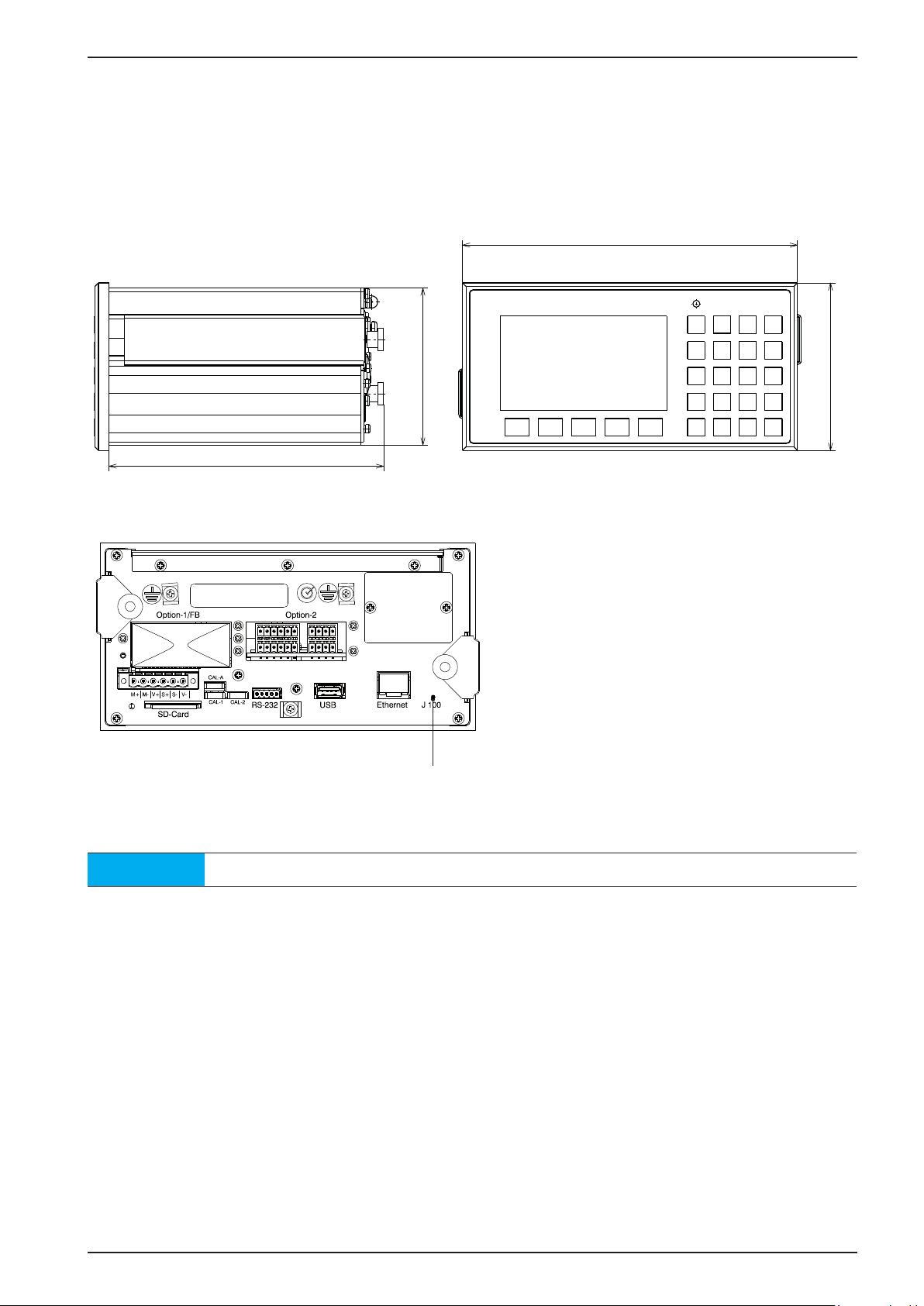
3.3 Housing
192
3.3.1 Housing dimensions
The keypad and the display form one unit with the front. A rectangular cut-out is required for the installation.
Cable connections are made at the back of the housing.
90
157
Front view Side view
Reset key
Back view
96
Note
All dimensions in mm.
Sartorius EN-9
Page 20
Process Controller PR 5500 Instrument Manual
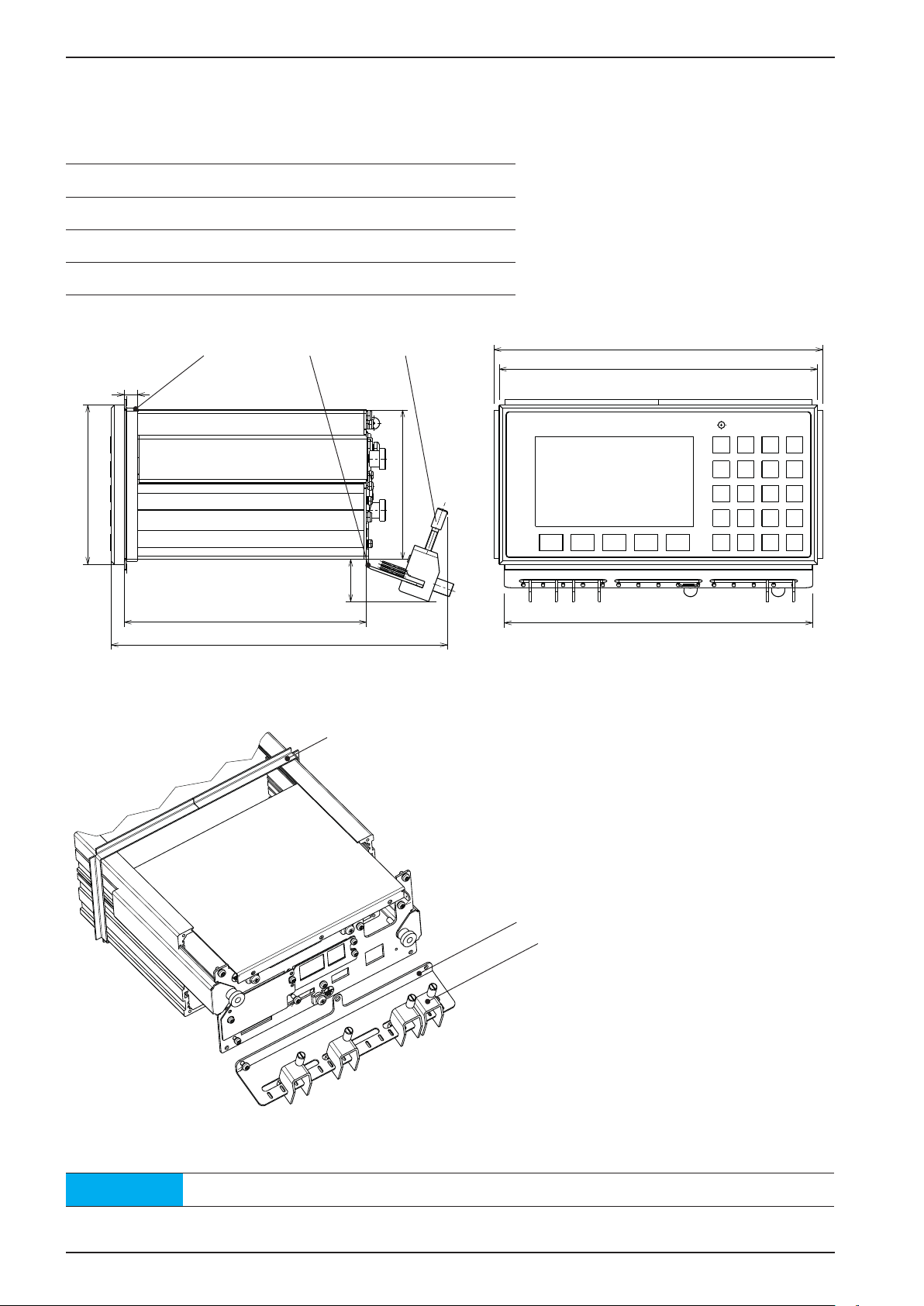
3.3.2 Housing Dimensions with Strain Relief and Reinforcing frame
96
199
The dimensions with the following options must be observed for installation:
Pos. Designation
1 Reinforcing frame
2 Screen clamping rail
3 Cable clamps
1 2 3
8
90
25
146 186
203
Side view Front view
1
192
2
3
Back view
Note
All dimensions in mm.
EN-10 Sartorius
Page 21

PR 5500 Instrument Manual Process Controller
3.3.3 Control Panel Cut-Out
The control panel cut-out must be made before installing the unit.
+0.5
91
+0.5
187
Note
All dimensions in mm.
Sartorius EN-11
Page 22
Process Controller PR 5500 Instrument Manual
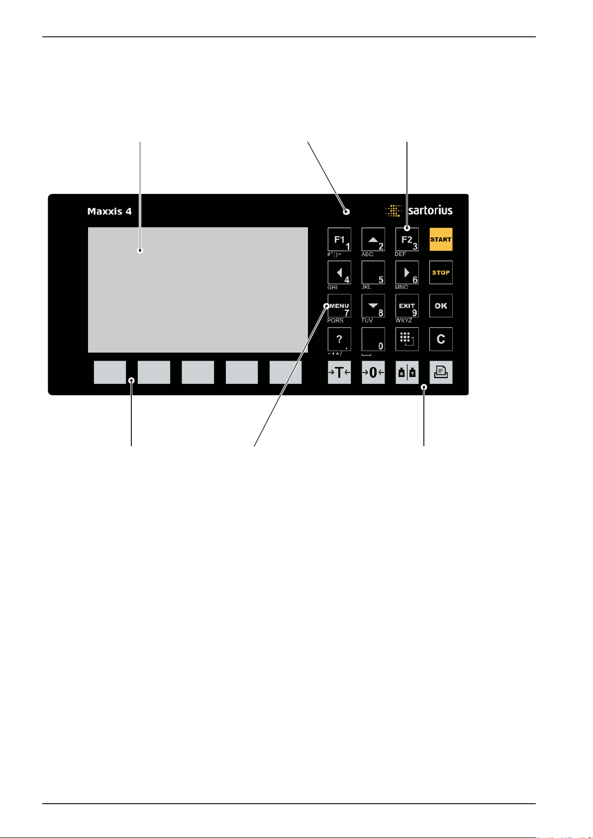
3.4 Display and Control Panel
3.4.1 Overview
4.3” color display LED Alphanumeric/function keys
Softkeys Navigation/Menu keys Indicator keys
EN-12 Sartorius
Page 23

PR 5500 Instrument Manual Process Controller
3.4.2 Display
The TFT display shows weight values of up to 7 digits with a decimal point and a plus or minus sign. Available
weight units are t, kg, g, mg, lb and oz.
The current weight value is displayed under the weight display as a bar graph in relation to the maximum
capacity. When the maximum capacity (Max) reaches 100 %, the bar graph is located on the right.
Bargraph Weight type/polarity sign/Standstill Status display Weight value Symbols/Mass unit
info line
Sartorius EN-13
Page 24
Process Controller PR 5500 Instrument Manual
Value type/Polarity sign Zero/Standstill/Dosing/Monitor. Symbols Mass unit
B
G
NET
T
PT
no indication
User
Setp
Diff
Gross weight Weight value
standstill
Gross weight in NTEP or
NSC mode
Net weight
(Net = gross - tare)
Tare weight
Preset tare
not tared
- Test value
- Gross, not tared
additional weight value,
application-specific
function
U
The gross weight
value is within ±¼ d
of zero
Filling mode:
flashes when filling is
“held”; rapid flashing
indicates “error”
Pendeo load cells:
plausibility monito-
ring; average value
deviation of each load
cell
Pendeo load cells:
Temperature control;
1…n load cells are
above/below the permissible temperature
!
R1
R2
R3
WP-A
Max
Min
t
kg
g
mg
lb
oz
Value not permissible in
legal metrology (e.g. 10-fold
resolution, deactived load cell)
Range 1
Range 2
Range 3
Weighing point A
Maximum capacity
(weighing range)
Minimum weight
+
–
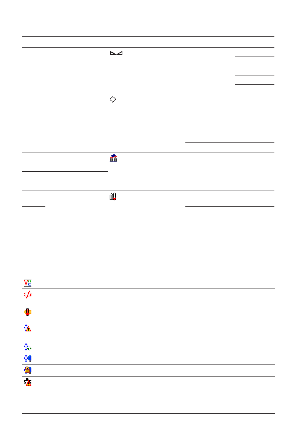
Status icons in the info line
Icon Description
Positiv value
Negativ value
Remote control via VNC (Virtual Network Computing) is active.
- The clock battery is empty.
- The standby battery is empty.
The standby battery is too hot and is not charging. If this does not go away, then the ambient
temperature must be checked, see Chapter 3.4.3.2.
- A USB device has been connected that is not supported.
- The max. current of i
Check newly connected devices.
USB stick recognized and ready for use.
Stick is in use and may not be removed.
IP address conflict in network settings
= 200 mA has been exceeded.
max
EN-14 Sartorius
Page 25
PR 5500 Instrument Manual Process Controller
3.4.3 Operating Elements
3.4.3.1 Front keys
The following table shows the basic meanings of symbols for the front keys. The keys could have additional
meanings depending on the applications used.
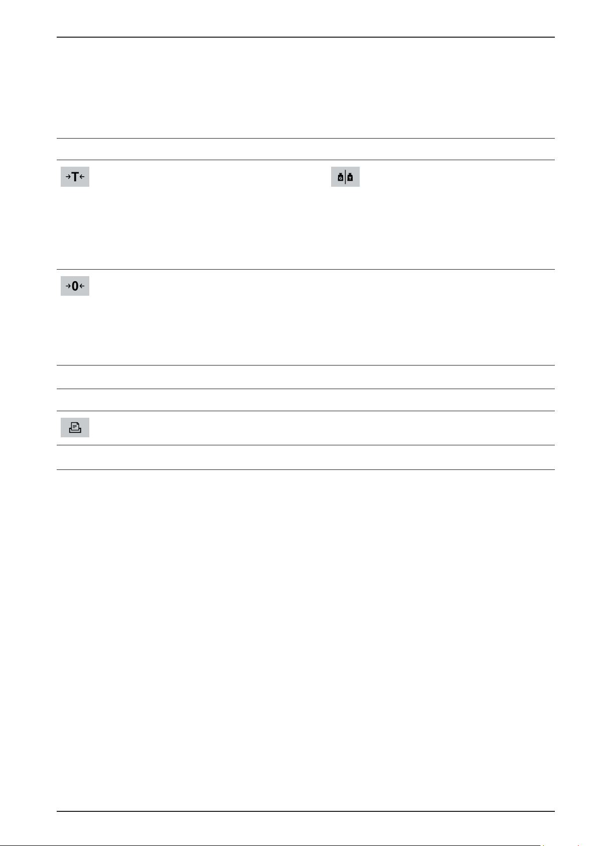
Indicator keys
Tare
The current gross weight is stored in
the tare memory if
- the weight value is stable
- the device is not in error status
(function dependent on
configuration)
Sets gross weight to zero if
- the weight value is stable
- the weight is within the zero
(function dependent on
configuration)
Application keys
Starts an application-specific
printout.
Display gross/tare weight
You switch to the next weight by
pressing the key (only tared scale).
During calibration, pressing this key
switches the weight to a 10-fold
resolution for 5 seconds.
setting range
Sartorius EN-15
Page 26
Process Controller PR 5500 Instrument Manual
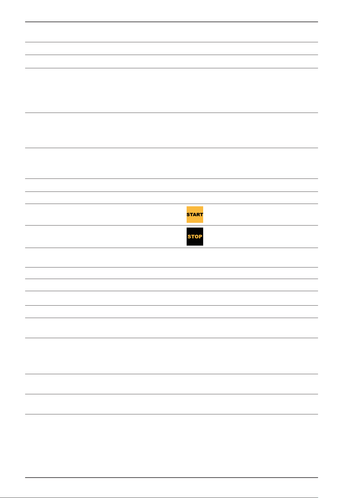
Navigation/menu keys
Function keys
F1
F2
Scroll up in the menu
Scroll down in the menu
- Cursor moves to the left
- Selection
- Exit the menu window
- Cursor moves to the right.
- Selection
- Confirm entry/selection
Assign with a defined function
(Operating parameters menu).
Assign with a defined function
(Operating parameters menu).
OK
EXIT
C
Soft key
1… 5
MENU
Confirm entry/selection
- Cancel entry/selection (after a
security prompt), without saving
the change.
- Exit the parameter/menu
window
Pressing the Delete key deletes
individual characters (within an
entry) or entire character sections,
see also page 17.
Select corresponding menu
functions, see also Chapter 3.4.3.2.
Switches to the Operating menu.
Starts an application-specific
function.
Stops an application-specific
function.
?
LED
Operating state Color LED status
Normal operation turned off
Power failure <5 seconds red flashing slowly After 5 seconds, the unit will
Power failure >5 seconds red flashing quickly The device performs a data
After backup the power failure is still
existing
Power voltage is on turned off The device performs a warm start,
Displays the corresponding Help
window.
continue normally.
backup. Is then the power on,
the unit returns to the normal
operation (LED turned off).
turned off The unit turns off.
see Chapter 5.1.3.
EN-16 Sartorius
Page 27
PR 5500 Instrument Manual Process Controller
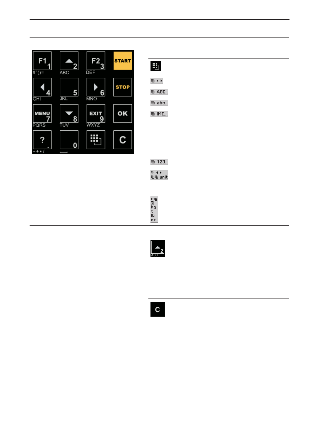
Alphanumeric keypad
Toggle key
Pressing this will toggle between the following
input modes:
- Cursor
- Uppercase letters
- Lowercase letters
- Pinyin
When Chinese was selected or set under
[Operating parameters] - [Input method].
- Hepburn
When Japanese was selected or set under
[Operating parameters] - [Input method].
- Numbers
- Units
Double-click on the toggle key opens a small
selection window.
Select the unit with cursor keys / and
confirm with
Input without character table
Pressing this once will display the first character,
e.g. 'A' in the cursor position. Pressing it twice
will display 'B' in the cursor position and threetimes will display 'C.'
Waiting approx. 2 seconds will complete the
character entry.
If only numeric values are required for input,
letters are not enabled.
You can delete the character to the left of the
cursor by pressing the Delete key C during entry.
Numerical value input (e.g. weight value):
Delete the content of the input field by pressing
the Delete key
OK.
C.
Sartorius EN-17
Page 28
Process Controller PR 5500 Instrument Manual
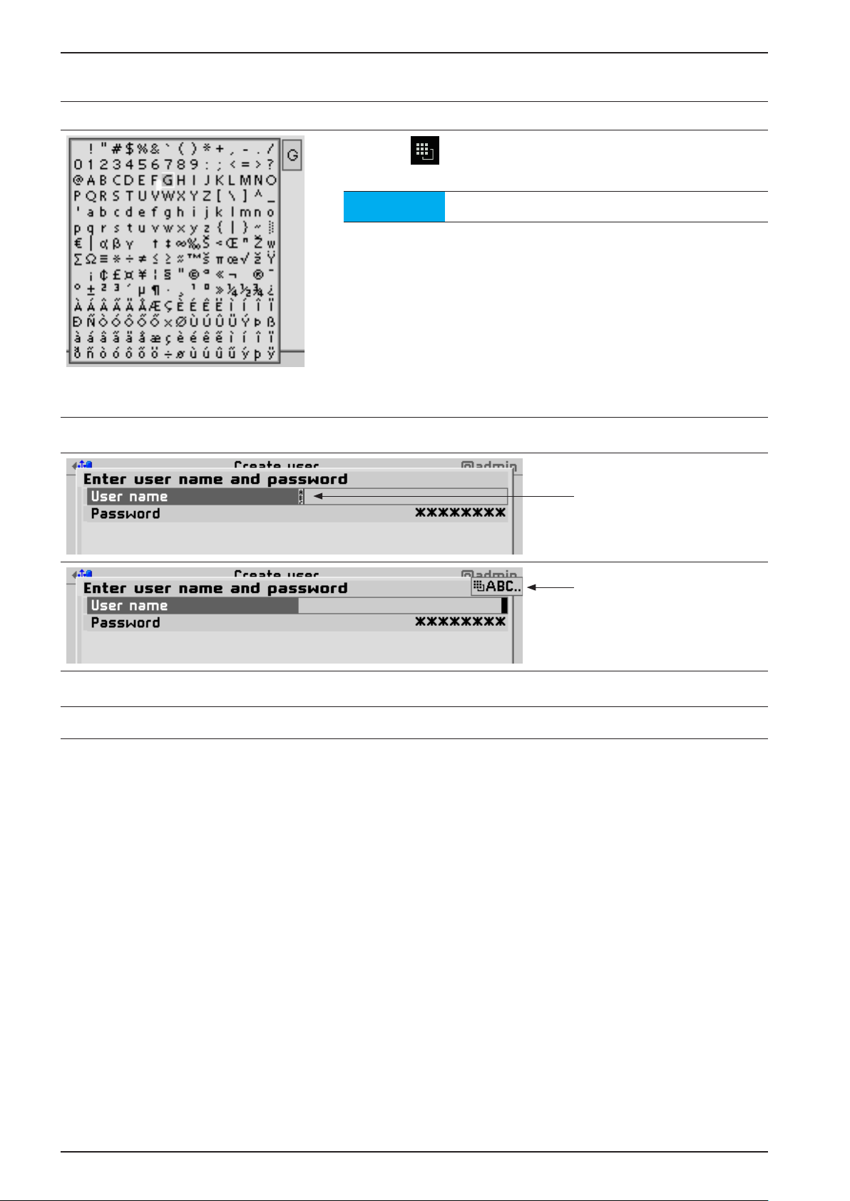
Input with character table
Double-clicking the key displays the character
table.
Input field
Note
The toggle function is turned off.
Procedure
tt Select the desired character with the cursor.
ty The selected character is shown magnified in
the field at the top right.
tt Press the
the input field.
tt Another double-click on the toggle key and
other characters can be input as described
previously.
OK key to enter the character in
Left of the input field is
displayed whether numeric
and/or alphabetical
characters can be entered.
The respective setting is
displayed.
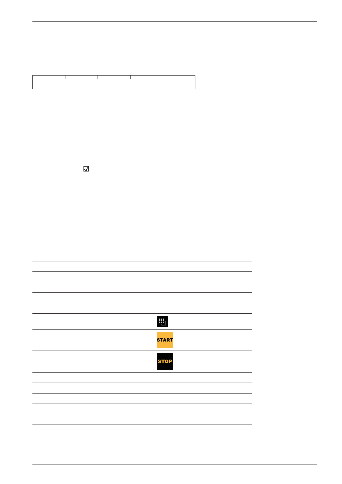
Keyboard shortcuts
STOP
+
EXIT
Trigger a cold start, see also Chapter 5.19.3.
EN-18 Sartorius
Page 29
PR 5500 Instrument Manual Process Controller
3.4.3.2 Operation Using Soft Keys
The functions of the five soft keys below the graphic display are indicated in the bottommost text line of the
display. In the descriptions of operating sequences which entail the use of soft keys, the soft key function to be
selected is shown in square brackets; the soft key symbol is not displayed, e.g. [Save].
Standard Save
3.4.3.3 Selection using the Navigation Keys
Menu
You can navigate menus using the cursor keys, the
Parameters
Individual parameters are selected using the / keys.
The required values/texts are entered via the alphanumeric keys.
Checkmarks are set using the OK key.
If the list of parameters is long, a vertical bar graph on the left (black/gray) shows which part of the list is
displayed.
Available selection lists are indicated by the following arrow .
The parameter is selected in the selection list via the
3.4.3.4 PC Keys
The device can also be operated via a PC keyboard. The corresponding key assignments can be viewed in the
following table, see also Chapter 4.3.3.2.
PC keyboard Front keypad
F1 F1
F2 F2
F3 ?
OK key and the EXIT key.
OK key.
F4 MENU
F5 to F9 Soft key 1 to 5
F10
F11
F12
ESC
Cursor keys: , , , , , ,
ENTER
Backspace
Numeric keypad Alphanumeric keypad
EXIT
OK
C
3.4.4 Operation using the VNC Program
User interface, see Chapters 3.4.1, 3.4.2 and 3.4.3.1.
Sartorius EN-19
Page 30
Process Controller PR 5500 Instrument Manual
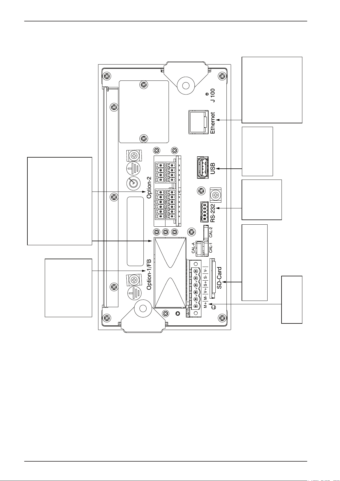
3.5 Overview of Connections
or
24 V DC
100…240 V AC
LAN port
(builtin) for
- remote access via VNC
- software flash
- communication/data exchange:
OPC, ModBus-TCP
USB 2.0 port
(builtin) for
USB stick, USB keyboard,
USB barcode scanner,
USB printer
- external I/O devices:
ModBus-TCP
- printer
Interfaces
- Option-1 and/or Opton-2:
Serial ports RS-485 (2x) PR 5500/04 and
Serial ports RS-232 (2x) PR 5500/32
One channel can be used to connect
an IS-platform without external
power supply.
Option-FB
Fieldbus interfaces
one option only
- ProfiBus-DP PR 1721/61
- Option-1 and/or Option-2:
Analogue I/O PR 5500/07
- Option-1 and/or Option-2:
Digital I/O PR 5500/12, ../13, ../17
or
- DeviceNet PR 1721/64
- CC-Link PR 1721/65
- ProfiNet I/O PR 1721/66
- EtherNet-IP PR 1721/67
Serial port RS-232
(builtin)
for
- printer
- remote display
- external scales
SD card port (builtin)
SD card will be used as memory
extension, not to transport data.
WP A
Internal weighing point
PR 5500/10 (W1)
EN-20 Sartorius
Page 31

PR 5500 Instrument Manual Process Controller
3.5.1 Plug-in Cards
Product ID Description Position
PR 5500/04
2 serial RS-485 interfaces
PR 5500/07
1 analog input
1 analog output
PR 5500/10 (W1)
Weighing electronics
The interface can be configured via
the software.
For more information, see
Chapter 4.4.1.
Analog input:
internal 14 bits binary = 20,000
counts,
@ e.g. 0 to 20 mA/0 to 10 V
Analog output:
internal 16 Bits = 65536 counts,
resolution of 20,000 @ 20 mA
For more information, see
Chapter 4.4.3.
Internal weighing electronics for
connecting load cells or weighing
platforms in non-hazardous areas.
A max. of two internal weighing
electronics systems can be
connected.
For more information, see
Chapter 4.4.4.
Option-1/FB and/or Option-2
Option-1/FB and/or Option-2
WP A
PR 5500/12
4 digital inputs
4 digital outputs
PR 5500/13
4 digital inputs
4 digital outputs
PR 5500/17
6 digital inputs
8 digital outputs
PR 5500/32
2 serial RS-232 interfaces
4 passive opto-decoupled inputs
4 relay outputs with potential-free
change-over contacts
For more information, see
Chapter 4.4.5.
4 active opto-decoupled inputs
4 relay outputs with potential-free
change-over contacts
For more information, see
Chapter 4.4.6.
6 passive opto-decoupled inputs
8 passive opto-decoupled outputs
For more information, see
Chapter 4.4.7.
The interface can be configured via
the software.
For more information, see
Chapter 4.4.2.
Option-1/FB and/or Option-2
Option-1/FB and/or Option-2
Option-1/FB and/or Option-2
Option-1/FB and/or Option-2
Sartorius EN-21
Page 32

Process Controller PR 5500 Instrument Manual
Product ID Description Position
PR 1721/61
ProfiBus-DP
PR 1721/64
DeviceNet
PR 1721/65
CC-Link
PR 1721/66
ProfiNet I/O
PR 1721/67
EtherNet/IP
ProfiBus-DP-V0 Slave with
9.6 kbit/s to 12 Mbps, Auto
baud rate detection; For more
information, see Chapter 4.4.8.
DeviceNet Master-Slave with 125,
250 and 500 kbps
For more information, see
Chapter 4.4.9.
CC-Link Slave with 156, 625 kbps,
2.5, 5, 10 Mbps
For more information, see
Chapter 4.4.10.
ProfiNet I/O with 10 and 100 Mbps
Autodetection (10/100, HalfDX/
FullDX)
For more information, see
Chapter 4.4.11.
EtherNet-IP with 10 and 100 Mbps
Autodetection (10/100, HalfDX/
FullDX)
For more information, see
Chapter 4.4.12.
Option-1/FB
(Carrier card installed in reversed
position)
Option-1/FB
(Carrier card installed in reversed
position)
Option-1/FB
(Carrier card installed in reversed
position)
Option-1/FB
(Carrier card installed in reversed
position)
Option-1/FB
(Carrier card installed in reversed
position)
EN-22 Sartorius
Page 33

PR 5500 Instrument Manual Process Controller
3.5.2 Application Licenses
Examples of application licenses:
Type Function
PR 5500/92 PR 1792 OPC server
(AccessIt 2.0 license incl.)
PR 5500/83 Batching
Examples of application packages:
Checkweighing
Automatic dosing and manual filling
For product details, see corresponding data sheets/manuals.
Applications purchased from Sartorius Intec may only be changed as per a source code agreement.
Sartorius EN-23
Page 34

Process Controller PR 5500 Instrument Manual
3.6 Instrument Versions
3.6.1 Combinatorics for the Options
Name Accessory Code no. Description Chapter
Housing:
Control cabinet housing Standard 3.3.1
Housing mounting parts:
Strain relief for connecting cables L14 3.3.2
Reinforcing frame L15 3.3.2
Elektronik:
Analog/digital
converter
Power supply:
Power supply
PR5500/10 W1
L0 100-240 V Version; standard 2.4.3.1
L8 24 V Version 2.4.3.2
WPA: Weighing electronics board 4.4.4
EN-24 Sartorius
Page 35

PR 5500 Instrument Manual Process Controller
Name Accessory Code no. Description Chapter
Interface cards:
2x RS-485
interface
Analog inputs
and outputs
Digital inputs
and outputs
Digital inputs
and outputs
Digital inputs
and outputs
PR 5500/04
PR 5500/07
PR 5500/12
PR 5500/13
PR 5500/17
B15
B25
B16
B26
B18
B28
B17
B27
B19
B29
Option-1/FB: 2 serial interfaces
Option-2: 2 serial interfaces
Option-1/FB: 1 analog input and 1 analog output
(0/4 to 20 mA)
Option-2: 1 analog input and 1 analog output
(0/4 to 20 mA)
Option-1/FB: 4 passive opto-decoupled inputs
and 4 relay outputs
Option-2: 4 passive opto-decoupled inputs
and 4 relay outputs
Option-1/FB: 4 active opto-decoupled inputs and
4 relay outputs
Option-2: 4 active opto-decoupled inputs and
4 relay outputs
Option-1/FB: 6 passive opto-decoupled inputs
and 8 passive opto-decoupled
outputs
Option-2: 6 passive opto-decoupled inputs
and 8 passive opto-decoupled
outputs
4.4.1
4.4.3
4.4.5.1,
4.4.5.2
4.4.6.1,
4.4.6.2
4.4.7.1,
4.4.7.2
2x RS-232
interface
Fieldbus cards:
ProfiBus-DP PR 1721/61 C21 Option-1/FB (carrier plate is mounted reversed) 4.4.8
DeviceNet PR 1721/64 C24 Option-1/FB (carrier plate is mounted reversed) 4.4.9
CC-Link PR 1721/65 C25 Option-1/FB (carrier plate is mounted reversed) 4.4.10
ProfiNet I/O PR 1721/66 C26 Option-1/FB (carrier plate is mounted reversed) 4.4.11
EtherNet-IP PR 1721/67 C27 Option-1/FB (carrier plate is mounted reversed) 4.4.12
PR 5500/32
B14
B24
Option-1/FB: 2 serial interfaces
4.4.2
Option-2: 2 serial interfaces
Sartorius EN-25
Page 36

Process Controller PR 5500 Instrument Manual
Name Accessory Code no. Description Chapter
Applications/Alibi memory/OPC server:
Basic H0 Standard application
Phase PR 5500/81 I4 Application (OPC license incl.)
Batching PR 5500/83 I6 Application
IBC PR 5500/86 I11 Application
Tilt Correction PR 5500/87 I12 License (only ‚Basic‘ application)
Alibi Memory PR 5500/91 E5 License
OPC server PR 5500/92 E6 Use of the PR 1792 OPC server
(AccessIt 2.0 license incl.)
Batch modes PR 5500/93 E9 Special license for using in individual
programming
Device Model
The marking (e.g. PR 5500-W1-L0-C21-B15-B27-H0-E5) of the device model (basic device + options) is located
on a label on the back of the instrument.
see corresponding
manual
EN-26 Sartorius
Page 37

PR 5500 Instrument Manual Device Installation
4 Device Installation
4.1 General Information
Before starting work, please read Chapter 2 and follow all instructions.
Further procedures:
tt Check the consignment: make sure that all components are present.
tt Safety check: inspect all components for damage.
tt Make sure that the on-site installation is correct and complete including cables, e.g. power cable fuse
protection, load cells, junction box, data cables, console/cabinet, etc.
tt If necessary, install the plug-in cards (device must be disconnected from all voltage sources).
tt Follow all device installation instructions related to application, safety, ventilation, sealing and
environmental influences.
tt Connect the cable from the junction box or platform/load cell.
tt If applicable: connect other data cables, power cables, etc.
tt Connect the power cable.
tt Check the installation.
Sartorius EN-31
Page 38

Device Installation PR 5500 Instrument Manual
4.2 Mechanical Preparation
Have all required parts, technical documents and tools at hand for installation.
- Measurement cables should be kept away from power equipment.
- Signal cables and measurement cables should be installed separately from electric power lines.
- It is recommended to lay measurement cables in separate cable conduits.
- Data cables should be crossed at right angles.
tt For the control panel cutout for the device made e.g. in the control cabinet door; see Chapter
tt Install device.
tt Secure the cable at the place of installation; e.g., using cable ties.
tt Remove the insulation from the cable ends and keep the strands short.
Connect the screen to device grounding terminal or screen clamping rail; see Chapter 4.2.1.1
tt
tt Connect the ground or equipotential bonding conductor to the device grounding terminal; see
Chapter 4.2.1.2.
3.3.3.
EN-28 Sartorius
Page 39

PR 5500 Instrument Manual Device Installation
4.2.1.1 Connecting the Screen to the Screen Clamping Rail
The screen must be connected to the screen clamping rail using delivered screen clamps as pictured below.
4.2.1.2 Connecting the Equipotential Bonding Conductor
The equipotential bonding conductor (1) must be connected as pictured below.
1
Sartorius EN-29
Page 40

Device Installation PR 5500 Instrument Manual
4.3 Hardware Construction
4.3.1 Main Board
741 2 3 5 6
10 9 812 11
The following elements are located on the main board:
Pos. Name Pos. Name
1 Reset key 7 Slot for fieldbus and option cards, Option-1/FB
2 Ethernet port, internal 8 Weighing electronics board W1
3 USB connection 9 Stand-by battery (for data recovery)
4 Slot for option cards, Option-2 10
5 Connection for RS-232 interface, internal 11 Color-graphic display
6 SD card slot 12 Power adaptor
Note
LED list see Chapter 13.4.
Clock battery (see Chapter 9.1)
EN-30 Sartorius
Page 41

PR 5500 Instrument Manual Device Installation
4.3.2 Network Port
The device has an internal Ethernet port.
4.3.2.1 Ethernet Port
The Ethernet port contains a powerful TCP/IP interface connection with transfer rates of 10 or 100 Mbps.
Function tests can be made via the LEDs (green and yellow) in the RJ-45 socket.
Transmission rate
Connection mode
Cables
Cable impedance
Potential isolation
Cable length
Connection
10 Mbps (10 Base-T),
100 Mbps (100 Base-T),
full/half duplex, auto-detection
Point to point
CAT 5 patch cable, twisted pair,
screened
150 ¥
Yes
Max. 115 m
RJ-45 socket on the device back
Yellow: lights up when there is an
existing connection (link)
Green: flashes when there is data
traffic (activity)
4.3.2.2 Notebook/PC Connection
Remote operation of the device from a notebook/PC
is possible (install VNC software version 3.3.7* on the
notebook/PC).
For network address settings, see Chapter 5.6.1.
* Sartorius Intec guarantees the functionality only if this
version is used.
Sartorius EN-31
Page 42

Device Installation PR 5500 Instrument Manual
4.3.3 USB Connection
The USB connection is located on the back of the device.
Type
Max. current
Possible
Connection
Devices
USB 2.0, Type A
i
= 200 mA
max
- USB stick
- External keyboard
- Barcode reader
- Printer (non-GDI)
- External splitter (hub)
Data integrity cannot be guaranteed in the case of a power failure when using a
USB stick via a splitter (HUB).
!
Caution
4.3.3.1 USB Stick
All commercially-available USB sticks can be used.
4.3.3.2 External PC Keyboard
The device has an alphanumeric keypad and a USB connection for an external PC keyboard on the back of the
device. Both operating functions are equivalent and either one can be used.
PC
keyboard
Keys F1 F2 ? MENU
Soft
key 1
Soft
key 2
Soft
key 3
Soft
key 4
Soft
key 5
START STOP
PC
keyboard
Keys EXIT C OK , , ,
You can set the key assignment for the connected keyboard under [System Setup]-[Operating Parameters][USB keyboard layout]:
- [German QWERTZ]
- [French AZERTY]
- [Italian QWERTY]
- [Spanish QWERTY]
- [English QWERTY]
- [Russian QWERTY/йцукен]
EN-32 Sartorius
Page 43

PR 5500 Instrument Manual Device Installation
!
Caution
Before connecting the keyboard, make sure: Current consumption i <200 mA.
An electronic current limiting prevents overloads.
1 2 3 4 5 6 7 8
Sartorius EN-33
Page 44

Device Installation PR 5500 Instrument Manual
4.3.3.3 Barcode scanner
A barcode scanner can be connected to the USB interface on the back of the device as an alternative to an
external keyboard.
Before connecting the barcode scanner, make sure: current consumption i <200 mA.
An electronic current limiting prevents overloads.
!
Caution
1 2 3 4 5 6 7 8
Barcode scanner settings are made by scanning the corresponding code (see manual).
We recommend setting 3 redundant read processes to ensure secure read values.
To confirm each read process via the key field, the automatic CR function of the scanner must
be switched off.
EN-34 Sartorius
Page 45

PR 5500 Instrument Manual Device Installation
4.3.3.4 Printer
The following USB printers can be used:
- YDP14IS-OCEUV
- EPSON TM-U220 und EPSON LQ-300K
- Line printer
- Printer with ESC/P2 control
- Printer with PCL5 control
4.3.3.5 External HUB
All commercially-available HUBs can be used.
All connected USB devices + HUB: current consumption i <200 mA
or use a power supply for the HUB.
!
Caution
Sartorius EN-35
Page 46

Device Installation PR 5500 Instrument Manual
4.3.4 SD Card Slot
The internal SD card slot is located on the back of the device. It comes with an appropriate SD card. The SD card
is only used for storage; it is not used for data transfers.
Note
The following data are saved to the SD card:
- The backup directory for the configuration and database
- A copy of the current version of the BIOS, firmware and application
- A copy of the delivery version of the BIOS, firmware and application
- Manuals
You also have the option of saving application data.
!
Caution
The SD card is protected by a battery in case of a power failure, i.e. the current process running (e.g. reading
data) is carried out and completed.
Only Sartorius Intec-supplied SD cards may be used. There is no warranty for third-party
cards.
The SD card is a fixed component of the device.
- The SD card may only be removed together with the SIL chip during servicing
(replacing a defective device, see Chapter 13.7).
- The SD card may not be used for data transfers.
- The SD card may not be used in Notebook/PC.
EN-42 Sartorius
Page 47

PR 5500 Instrument Manual Device Installation
4.3.5 RS-232 Interface (built-in)
The device is equipped with an integrated RS-232 interface. This interface is configurable, and can be used, for
example, for data transmission to a remote display or printer.
Connection
Number of
channels
Type
Transmission rate
Parity
Data bits
Input signal level
Output signal level
Number of signals
Potential isolation
Cable gauge
Terminal, 5-pin
1
RS-232, full duplex
300 to 115k2 Bit/sec
None, odd, even
7/8 bit
Logic 1 (high) - 3 to - 15 V
Logic 0 (low) + 3 to + 15 V
Logic 1 (high) - 5 V to - 15 V
Logic 0 (low) + 5 V to + 15 V
Input: Rx, CTS
Output: Tx, RTS
none
max. 1.5 mm
2
GNDCTSRxDTxDRTS
RTS
TxD
RxD
CTS
GND
Cable length
Cable type
max. 15 m
Twisted pair, screened
(e.g. LifYCY 3x2x0.20), 1 pair of
wires for ground (GND).
Sartorius EN-37
Page 48

Device Installation PR 5500 Instrument Manual
4.3.5.1 Connecting a PR 5110 Remote Display via RS-232
The remote display can be connected via the built-in RS-232 interface.
PR 5500
RS-232:
Builtin or/oder
PR5510/02 or/oder
PR5510/04
5
4
3
2
1
RS-232
RTS
TxD
RxD
CTS
GND
D-Sub 9-contact male connector/
9-polige D-Sub Buchse (male)
8
2
3
7
5
5-pin plug-in terminal block/
5-polige steckbare Schraubklemme
PR 5500 Configuration PR 5110 Configuration
[System setup] – [Connected devices] –
[Remote display] – [Interface] – [Built-in RS-232]
- - – 232
PR 5110
CTS
RxD
TxD
RTS
GND
- 2 – -
- 3 – –
– 4 – WGH – W
– 5 – WY – C
EN-38 Sartorius
Page 49

PR 5500 Instrument Manual Device Installation
4.3.5.2 Connecting a YDP14IS Ticket Printer via RS-232
The YDP14IS-OCEUV ticket printer can be connected via the built-in RS-232 interface.
delievered adapter
mitgelieferter Adapter
PR 5500
RS-232
RTS
TxD
RxD
3
RxD
2
TxD
6
YDP 14IS-OCEUV
RS-232
CTS
GND
8
5
PR 5500 Configuration Printer Configuration
[System setup]-[Connected devices]-[Printer][Interface]-[Built-in RS-232]:
- [Protocol] to 'RTS/CTS'
- [Baud Rate] to '9600'
The printer must be set to Line Mode (the factory
setting is Page Mode). Press the FEED button
to change modes; please refer to the operating
instructions delivered with the printer.
- [Data Bits] to '8'
- [Parity] to 'none'
- [Stop Bits] to '1'
- [Printer Type] to [Unchanged]
RDY
GND
4.3.5.3 Connecting Additional Printers
The following serial printers can also be used:
- Epson TM-U295
- Printer with ESC/P2 protocol
Sartorius EN-39
Page 50

Device Installation PR 5500 Instrument Manual
4.3.5.4 Connecting an IS Platform via RS-232
A platform using an xBPI or SBI protocol can be connected via the built-in RS-232 interface.
PR 5500
RS-232
RTS
TxD
RxD
CTS
GND
Sartorius platform/Plattform
xBPI protocol (slave)/xBPI Protokoll (slave)
B
RxD
C
TxD
E
GND
K A B
J L C
H M D
G F E
AC/DC adapter/
AC/DC Adapter
12-contact male socket/
12-polige Buchse (male)
Configuration
[System setup] – [Weighing points] – [Weighing point X]:
[Interface]:
Note
[xBPI scale]
[Built-in RS-232]
For more information, see the platform manual.
EN-40 Sartorius
Page 51

PR 5500 Instrument Manual Device Installation
4.3.5.5 Connecting a Mettler-Scale via RS-232
A Mettler-Scale using MT-SICS protocol can be connected via the built-in RS-232 interface.
Example: Type XS6002SDR
PR 5500
RS-232
RTS
TxD
RxD
CTS
GND
Configuration PR 5500
[System setup] – [Weighing points] – [Weighing point X]:
[Interface]:
Mettler-Scale/Waage type/Typ XS6002SDR
MT-SICS protocol (slave)/MT-SCIS-Protokoll (slave)
8
3
2
7
5
[Mettler-Scale]
[Built-in RS-232]
RTS
RxD
TxD
CTS
GND
Parameter settings Mettler-Scale
see Chapter 5.17.2.
Note
For more information, see the Mettler-Scale
manual.
Sartorius EN-41
Page 52

Device Installation PR 5500 Instrument Manual
4.4 Accessories
4.4.1 PR 5500/04 2x RS-485 Interface
The plug-in card contains two channels. One channel can be used for connecting an IS platform without an
external power supply.
Note
The RS-485 interface can be selected and configured in the Setup menu.
Using the RS-485 interface is compulsory with a multi-point connection (Tristate status).
The RS-485 interface can also be used as a point-to-point connection.
The card is inserted in the Option 1/FB and/or Option 2 slot.
A max. of 2 PR 5500/04 cards can be installed!
Either the internal Weighingpoint or an IS platform without external power supply can be
used.
Internal
Connection
Number of
channels
Type
For external
power supply
Transmission rate
Signals
Contact strip
2
RS-485, full duplex (4-wire)
RS-485, half duplex (2-wire)
U= 24 V, 3 W (briefly up to 6 W)
300 to 115 K2 Bit/sec
TxA, RxA, TxB, RxB
Potential isolation
Cable gauge
Cable length
Cable type
External
connection
Dimensions
(LxWxH)
Weight
Yes
max. 1.5 mm
max. 1000 m
Twisted pair, screened
(e.g. LifYCY 3x2x0.20), 1 pair of
wires for ground (GND).
2x terminal, 7-pin
50x45x18 mm
Approx. 35 g
2
EN-42 Sartorius
Page 53

PR 5500 Instrument Manual Device Installation
PR 5500/04 2x RS-485 Interface
GND
A-GNDI
+24 V
A-TxB
A-RxB
A-TxA
A-RxA
1 2 3 4 5 6 7 8
o
o
A
B
B-RxB
B-TxA
B-TxB
B-GNDI
+24 V
GND
+
o
+
+
A-RxB
A-TxA
A-TxB
A-GNDI
+24 V
GND
A
B
{
1 2 3 4 5 6 7 8
B-RxA
A-RxA
{
1 2 3 4 5 6 7 8
{
BA
BA
{
↓
↓
ON
ON
1 2 3 4 5 6 7 8
B-RxA
B-RxB
B-TxA
B-TxB
B-GNDI
+24 V
GND
Coding of Option-1/Option-2
tt Terminal block: Insert the coding pin into the slot of the position marked in gray.
tt Terminal: Remove (pinch off) the corresponding coding ridge.
Note
The terminal coding is described in Chapter 13.5.
Sartorius EN-43
Page 54

Device Installation PR 5500 Instrument Manual
Block diagram 2x RS-485
ON
PR 5500/04
DC
DC
RxD/TxD-P
RxD/TxD-N
S6
S7
S8
S5
GND
+24 V
B-GNDI
1K6
B-TxB
B
120
B-TxA
1K6
B-RxB
120
B-RxA
DC
DC
RxD/TxD-P
RxD/TxD-N
S2
S3
S4
S1
1K6
1K6
120
120
GND
+24 V
A-GNDI
A-TxB
A-TxA
A-RxB
A-RxA
A
{
A
1 2 3 4 5 6 7 8
B
{
↓
EN-44 Sartorius
Page 55

PR 5500 Instrument Manual Device Installation
S Function Settings for RS-485
1 Rx bus termination OFF: not connected ON: (A-RxA 120 ¥ A-RxB)
2 Tx pull-up resistor OFF: not connected ON: (A-TxB 1K6 ¥ +V)
3 Tx pull-down resistor OFF: not connected ON: (A-TxA 1K6 ¥ -V)
4 Tx bus termination OFF: not connected ON: (A-TxA 120 ¥ A-TxB)
5 Rx bus termination OFF: not connected ON: (B-RxA 120 ¥ B-RxB)
6 Tx pull-up resistor OFF: not connected ON: (B-TxB 1K6 ¥ +V)
7 Tx pull-down resistor OFF: not connected ON: (B-TxA 1K6 ¥ -V)
8 Tx bus termination OFF: not connected ON: (B-TxA 120 ¥ B-TxB)
Note
See block diagram on page 44.
4.4.1.1 Connecting to a PC or RS-485/RS-232 Converter
Point-to-point connection for the EW Com protocol (4-wire)
Example
PR 5500
PR 5500/04
RS-485-A
+ 24 V
DC
DC
1K6
S2
RxD/TxD-P
S4
RxD/TxD-N
120
S3
1K6
S1
120
A
GND
GNDI
A-TxB
A-TxA
A-RxB
A-RxA
RS-485 Converter
TxB
TxA
GND
+
RxB
RxA
-
1 2 3 4 5 6 7 8
A
{
↓ON
Switch settings
ON: S1
OFF: S2, S3, S4
Configuration
[System setup] – [Connected devices] – [PC via EW Com] – [Interface] – [Option-1 RS-485-A]
Sartorius EN-45
Page 56

Device Installation PR 5500 Instrument Manual
4.4.1.2 Connecting to a PLC or RS-485/RS-232 Converter
Point-to-point connection for the ModBus protocol (2-wire)
Example
PR 5500
PR 5500/04
RS-485-A
A
GND
PLC
+ 24 V
DC
DC
S2
RxD/TxD-P
RxD/TxD-N
GNDI
1K6
A-TxB
S4
120
A-TxA
S3
1K6
A-RxB
S1
120
A-RxA
1 2 3 4 5 6 7 8
A
{
↓ON
ModBus-RTU (master)
GND
TxB/RxB
TxA/RxA
Switch settings
ON: S2, S3, S4
OFF: S1
Configuration
[System setup] – [Connected devices] – [ModBus-RTU master] – [Interface] – [Option-1 RS-485-A]
EN-46 Sartorius
Page 57

PR 5500 Instrument Manual Device Installation
4.4.1.3 Connecting several PR 5500 Devices to a PC or RS-485/RS-232 Converter
Connection for the EW Com protocol.
Example
PR 5500
PR 5500/04
RS-485-A
PR 5500
PR 5500/04
RS-485-A
DC
DC
RxD/TxD-P
RxD/TxD-N
Switch settings/Schalterstellungen
ON: OFF: S1…S8
DC
DC
RxD/TxD-P
RxD/TxD-N
A
GND
+ 24 V
GNDI
1K6
S2
A-TxB
S4
120
A-TxA
S3
1K6
A-RxB
S1
120
A-RxA
1 2 3 4 5 6 7 8
A
{
↓
ON
RS-485 Converter
TxB
TxA
GND
+
RxB
RxA
-
A
GND
+ 24 V
GNDI
1K6
S2
A-TxB
S4
120
A-TxA
S3
1K6
A-RxB
S1
120
A-RxA
Switch settings/Schalterstellungen
ON: OFF: S1…S8
PR 5500
PR 5500/04
RS-485-A
DC
DC
Switch settings/Schalterstellungen
ON: S1
OFF: S2…S8
Configuration
RxD/TxD-P
RxD/TxD-N
1 2 3 4 5 6 7 8
A
{
↓
ON
A
GND
+ 24 V
GNDI
1K6
S2
A-TxB
S4
120
A-TxA
S3
1K6
A-RxB
S1
120
A-RxA
1 2 3 4 5 6 7 8
A
{
↓
ON
[System setup] – [Connected devices] – [PC via EW Com] – [Interface] – [Option-1 RS-485-A]
Sartorius EN-47
Page 58

Device Installation PR 5500 Instrument Manual
4.4.1.4 Connecting a PR 5110 Remote Display via RS-485
Connection via the RS-485 interface, 4-wire transmission, point-to-point, full duplex (simultaneous sending and
receiving possible) with the PR 5110 remote display.
Example
PR 5500
PR 5500/04
RS-485-A
DC
DC
RxD/TxD-P
RxD/TxD-N
1K6
S2
S4
120
S3
1K6
S1
120
GND
+ 24 V
GNDI
A-TxB
A-TxA
A-RxB
A-RxA
A
{
A
D-Sub 9-contact male connector/
9-polige D-Sub Buchse (male)
8
2
3
7
5
1 2 3 4 5 6 7 8
↓ON
5-pin plug-in terminal block/
5-polige steckbare Schraubklemme
5
4
3
2
1
RS-485
GNDI
RxB
RxA
TxB
TxA
S5
S2
1K6
S1
120
1K6
S3
RxD/TxD-P
S4
120
RxD/TxD-N
ON DIP
1 2 3 4 5
PR 5500 Switch settings PR 5110 Switch settings
ON: S1 ON: S1, S2, S3
PR5110
DC
DC
OFF: S2, S3, S4 OFF: S4, S5
PR 5500 Configuration PR 5110 Configuration
[System setup] – [Connected devices] – [Remote display] –
[Interface] – [Option-1 RS-485-A]
– – – 45
– 2 – –
– 3 – –
– 4 – WGH – W
– 5 – WY – C
EN-48 Sartorius
Page 59

PR 5500 Instrument Manual Device Installation
4.4.1.5 Connecting multiple PR 5110 Remote Displays via RS-485
Switch settings/Schalterstellungen
Switch settings/Schalterstellungen
Switch settings/Schalterstellungen
OFF: S4, S5
Connection of several remote displays via the RS-485 interface, 4-wire, full-duplex (simultaneous sending and
receiving possible).
Example
PR 5500
PR 5500/04
RS-485-A
DC
DC
Switch settings/Schalterstellungen
ON: S1
OFF: S2…S8
RxD/TxD-P
RxD/TxD-N
A
GND
+ 24 V
GNDI
1K6
S2
A-TxB
S4
120
A-TxA
S3
1K6
A-RxB
S1
120
A-RxA
1 2 3 4 5 6 7 8
A
{
↓
ON
D-Sub 9-contact male connector/
9-polige D-Sub Buchse (male)
8
2
3
7
5
RS-485
5
4
3
2
1
5-pin plug-in terminal block/
5-polige steckbare Schraubklemme
GNDI
RxB
RxA
TxB
TxA
PR5110
S5
S2
1K6
S1
120
1K6
S3
RxD/TxD-P
S4
120
RxD/TxD-N
ON DIP
1 2 3 4 5
ON: --OFF: S1, S2, S3, S4, S5
DC
DC
PR5110
8
2
3
7
5
RS-485
5
4
3
2
1
GNDI
RxB
RxA
TxB
TxA
S5
S2
1K6
S1
120
1K6
S3
RxD/TxD-P
S4
120
RxD/TxD-N
ON DIP
1 2 3 4 5
DC
DC
8
2
3
7
5
RS-485
5
4
3
2
1
GNDI
RxB
RxA
TxB
TxA
S2
1K6
120
1K6
S3
120
S5
S1
RxD/TxD-P
S4
RxD/TxD-N
ON DIP
1 2 3 4 5
ON: --OFF: S1, S2, S3, S4, S5
ON: S1, S2, S3
PR 5500 Configuration PR 5110 Configuration
[System setup] – [Connected devices] – [Remote display] –
– – – 45
[Interface] – [Option-1 RS-485-A]
– 2 – –
– 3 – –
– 4 – WGH – W
PR5110
DC
DC
– 5 – WY – C
Sartorius EN-49
Page 60

Device Installation PR 5500 Instrument Manual
4.4.1.6 Connecting the IS Platform via RS-485 (2-wire)
A platform using an xBPI or SBI protocol can be connected via the RS-485 interface.
Note
Example
PR 5500
PR 5500/04
RS-485-A
Only one platform can be supplied with power from the PR 5500 and the weighing
electronics board PR 5500/10 must not be connected.
Sartorius platform/Plattform
xBPI protocol (slave)/xBPI Protokoll (slave)
A
GND
+ 24 V
DC
DC
S2
RxD/TxD-P
RxD/TxD-N
GNDI
1K6
A-TxB
S4
120
A-TxA
S3
1K6
A-RxB
S1
120
A-RxA
1 2 3 4 5 6 7 8
A
{
↓ON
K
G
E
GND
L RxD - TxD - P
A RxD - TxD - N
K A B
J L C
H M D
G F E
RS-485
half-duplex/
halbduplex
12-contact male socket/
12-polige Buchse (male)
Switch settings
ON: S2, S3, S4
OFF: S1
Configuration
[System Setup] – [Weighing points] – [Weighing point A]:
[Interface]:
Note
AC/DC adapter/
AC/DC Adapter
[xBPI scale]
[Option-x RS-485-A]
For more information, see the platform manual.
EN-50 Sartorius
Page 61

PR 5500 Instrument Manual Device Installation
4.4.1.7 Connecting 4 Load Cells PR 6204 ‚Pendeo® Process‘/PR 6224 ‚Pendeo® Truck‘ via RS-485
Example
PR 6024/64S
LC 3
rd
bu
gn
gy
+
–
B
A
24 V DC
LED
1 AT
LC 1
+
–
B
A
rd
bu
gn
gy
PR 6024/62S
230 V AC
L
N
PE
equipotential bonding conductor
Potenzialausgleich
+
GND
24 V DC
1 A
PE – +
rd
bu
gn
gy
PR 6124/xxP
RS 5500 with/mit
PR 5500/04
RS-485-A
screen/Schirm
RS-485-B
LC 4
+
–
B
A
+ – B A
PS IND
rdbugn
gy
B A
LC 2
+
–
B
A
PR 6124/xxD
{
1 2 3 4 5 6 7 8
RS-485-BRS-485-A
{
rd
bu
gn
gy
ON
↓
screen/Schirm
or screen clamping rail/
oder Schirmklemmschiene
Note
For more information, see the load cell and junction box manuals.
Sartorius EN-51
Page 62

Device Installation PR 5500 Instrument Manual
4.4.2 PR 5500/32 2x RS-232 Interface
The plug-in card contains two channels. One channel can be used for connecting one IS platform without an
external power supply. The jumper (1) must then be plugged onto A-24 V or B-24V. When an IS platform is
connected without an external power supply, no analog weighing electronics board or no load cells may be
installed in the device.
The RS-232 interface can be selected and configured in the Setup menu.
The card is inserted in the Option 1 and/or Option 2 slot.
A max. of 2 PR 5500/32 cards can be installed!
Intern. connection
Extern. connection
Number of
channels
Type
Transmission rate
Parity
Data bits
Input signal level
Output signal level
Number of signals
A-24 VB-24 V 1
Potential isolation
Cable gauge
Contact strip
2x terminal, 7-pin
2
RS-232, full duplex
300…115K2 Bit/sec
None, odd, even
7/8 bit
Logic 1 (high) - 3… - 15 V
Logic 0 (low) + 3… + 15 V
Logic 1 (high) - 5 V… - 15 V
Logic 0 (low) + 5 V… + 15 V
Input: RxD, CTS
Output TxD, RTS
none
max. 1.5 mm
2
Cable length
Cable type
Power supply for
IS platform
Dimensions
(LxWxH)
Weight
max. 15 m
Twisted pair, screened
(e.g. LifYCY 3x2x0.20), 1 pair of
wires for ground (GND).
switchable to channel A or B
50x45x18 mm
Approx. 35 g
EN-52 Sartorius
Page 63

PR 5500 Instrument Manual Device Installation
PR 5500/32 2x RS-232 Interface
GND
A-RTS
A- +24 V
A-RxD
A-TxD
GND
A-CTS
A
24 V
AB
B
o
+
o
o
+
+
GND
GND
B-RTS
B- +24 V
A-RTS
A- +24 V
B-RxD
B-TxD
A-RxD
A-TxD
A
GND
B-CTS
A-CTS
GND
24 V
AB
B
B-CTS
B-RxD
B-TxD
B-RTS
B- +24 V
GND
Coding of Option-1/Option-2
tt Terminal block: Insert the coding pin into the slot of the position marked in gray.
tt Terminal: Remove (pinch off) the corresponding coding ridge.
Note
The terminal coding is described in Chapter 13.5.
GND
Sartorius EN-53
Page 64

Device Installation PR 5500 Instrument Manual
Block diagram 2x RS-232
PR 5500/32
GND
B- +24 V +24 V
B-RTS
B-TxD
B
B-RxD
B-CTS
GND
GND
A- +24 V +24 V
A-RTS
A-TxD
A-RxD
A-CTS
GND
A
EN-54 Sartorius
Page 65

PR 5500 Instrument Manual Device Installation
4.4.2.1 Connecting peripheral devices via RS-232
- Connecting the PR 5110 Remote Display via RS-232 (see built-in RS-232, Chapter 4.3.5.1)
- Connecting a YDP14IS Ticket Printer via RS-232 (see built-in RS-232, Chapter 4.3.5.2)
- Connecting a Mettler-Scale via RS-232 (see built-in RS-232, Chapter 4.3.5.5)
Sartorius EN-55
Page 66

Device Installation PR 5500 Instrument Manual
4.4.2.2 Connecting the IS Platform via RS-232
Using these option cards, you can connect an IS platform using the xBPI or SBI protocol.
Note
Example
PR 5500
PR 5500/32
RS-232-A
Only one platform can be supplied with power from the PR 5500 and no load cells may be
connected to the weighing electronics board PR 5500/10.
IS platform
xBPI protokoll (slave)
GND
A- +24 V +24 V
A-RTS
A-TxD
A-RxD
A-CTS
GND
K
G
B
C
E
H M D
GND
+24 V
RxD
TxD
GND
K A B
J L C
12-contact
male socket (male)
Jumper setting
Channel A A- +24 V
Configuration
[System Setup] – [Weighing points] – [Weighing point A]:
[Interface]:
Note
G F E
AC/DC adapter
[xBPI scale]
[Option-x RS-232-A]
For more information, see the platform manual.
EN-56 Sartorius
Page 67

PR 5500 Instrument Manual Device Installation
4.4.3 PR 5500/07 Analog Inputs and Outputs
The plug-in card for the available analog channels has 1 analog output (active) and 1 analog input.
The card is inserted in the Option 1/FB and/or Option 2 slot.
A max. of 2 PR 5500/07 cards can be installed!
PR 5500/07
DAC
D
A
ADC
D
A
DC
DC
+
AGND
25 K
50 K
10 E
200 E
I
0…20 mA
I
in
V
0…10 V
in
0…20 mA
out
AGND
AGND
AGND
Output
Output function
Output range
Output resolution
Linearity error
output
Temperature error
output
Zero point error
output
Max. error output
Load
Potential isolation
Cable
Input
Input range
Input resistance
Input resolution
Max. error input
Linearity error
input
Temperature error
input
Reserve input
Potenzialtrennung
Cable
1 active current output:
0/4 to 20 mA (max. 24 mA),
10 V output voltage via an external
500 ¥ resistor
Gross/Net/Display follows or
application-dependent
0/4 to 20 mA, configurable
Internal 16 Bits = 65536 counts,
resolution of 20,000 @ 20 mA
@ 0 - 20 mA: 0.04 %
@ 4 - 20 mA: 0.02 %
<100 ppm/K
0.05 %
<0.1 %
max. 0 to 500 ¥
Yes
<150 m screened
1 current or voltage input
0…10 V or 0…20 mA
100 k¥ for 10 V measuring input
200 ¥ for 20 mA measuring input
internal 14 Bits binary = 20,000
counts,
@ e.g. 0 to 20 mA/0 to 10 V
0.2 %
<0.02 %
<75 ppm/K
±15%, i.e. –1.5 V to +11.5 V
Yes, joint inputs and outputs
<150 m screened
Intern. connection
Extern. connection
Dimens. (LxWxH)
Weight
Contact strip
2x terminal, 6-pin
50x45x18 mm
Approx. 40 g
Sartorius EN-57
Page 68

Device Installation PR 5500 Instrument Manual
0…20 mA
in
I
0…10 V
AGND
V
in
AGND
AGND
o
+
o
o
+
+
0…20 mA
out
I
0…20 mA
in
I
0…10 V
AGND
V
Coding of Option-1/Option-2
tt Terminal block: Insert the coding pin into the slot of the position marked in gray.
tt Terminal: Remove (pinch off) the corresponding coding ridge.
Note
The terminal coding is described in Chapter 13.5.
in
AGND
AGND
0…20 mA
out
I
EN-58 Sartorius
Page 69

PR 5500 Instrument Manual Device Installation
4.4.4 PR 5500/10 Weighing Electronics Board
4.4.4.1 Specifications
The weighing electronics board is inserted in the WP A slot.
The CAL switch A (1) are located on the board.
Adjustment data and parameters are saved to the EAROM (non-volatile memory) of the weighing electronics
board.
Internal
connection
Load cell supply
Capacity (number
of load cells)
Sense input
Measurem. input
Dead load suppression
Sensitivity, min.
signal
Min. measuring
signal
Max. resolution
Linearity
Pin strip, 28-pin
12 V DC,
symmetrical to zero (U = ±6 V DC,
I
= 160 mA)
max
>
75 ¥, corresponding to 8 load
cells with 650 ¥ or 4 load cells
with 350 ¥
±6 V DC, with monitoring
0 to 36 mV DC, symmetrical to zero
max. 36 mV DC (dead load + range)
according to OIML R76 Class III
10,000 d: 0.2 mV/V at 12 V
excitation [0.24µV/d]
7.5 million counts internal
<0.003 %
Temperature coefficient zero (Tk
Temperature coefficient Vst (Tk
span
Cable length
<0.05 µV/K RTI,
<0.004 %/10K @ 1 mV/V
)
0
<±4 ppm/K
)
max. 300 m
1
Cable type
6-wire with screen for total cable
and screen for measurement cables,
e.g. PR 6135/..
Extern. connection
7-pin plug (male), screen
connection on housing and on
GNDA
Dimens. (LxWxH)
Weight
85x50x25 mm
approx. 60 g
Sartorius EN-59
Page 70

Device Installation PR 5500 Instrument Manual
4.4.4.2 General Information
There is one connection on the back of the housing for analog load cells or analog platforms (e.g. CAPP series)
depending on the model. The supply voltage is protected against short circuit and overload.
Do not shorten the load cell cable. Connect the prepared cable end and roll up the
remaining cable.
!
Caution
5 1
PROFIBUS DP
69
STOP
o
+
o
o
+
+
M+ M- V+ S+ S- V-
Terminal block Connection Description
+ M + Meas. + Signal/LC output
– M – Meas. – Signal/LC output
+ V + Supply + Exitation
+ S + Sense + Sense
– S – Sense – Sense
– V – Supply – Exitation
EN-60 Sartorius
Page 71

PR 5500 Instrument Manual Device Installation
4.4.4.3 Connecting a Load Cell with a 4-Wire Cable
The cable colors shown here are valid for Sartorius Intec load cells.
Color code:
bk = Black rd = Red
!
Caution
bu = Blue wh = White
gn = Green ye = Yellow
gy = Gray
gy
gn
Schirm
screen/
+ Meas.
M+ M– V+ S+ S– V–
PR 5500
equipotential bonding conductor
Potenzialausgleich
rd
– Meas.
+ Supply
bk
wh
+ Sense
bu
– Sense
– Supply
screen/Schirm
or screen clamping rail/
oder Schirmklemmschiene
Place the following links directly on the terminal block:
between + Supply (+V) and + Sense (+S)
between – Supply (-V) and – Sense (-S)
Sartorius EN-61
Page 72

Device Installation PR 5500 Instrument Manual
4.4.4.4 Connecting a Load Cell with a 6-Wire Cable
The cable colors shown here are valid for Sartorius Intec load cells.
Color code:
bk = Black rd = Red
!
Caution
bu = Blue wh = White
gn = Green ye = Yellow
gy = Gray
gn
Schirm
screen/
+ Meas.
M+ M– V+ S+ S– V–
PR 5500
equipotential bonding conductor
Potenzialausgleich
rdgybk
– Meas.
+ Supply
wh
+ Sense
bu
– Sense
– Supply
screen/Schirm
or screen clamping rail/
oder Schirmklemmschiene
EN-62 Sartorius
Page 73

PR 5500 Instrument Manual Device Installation
4.4.4.5 Connecting up to 8 Load Cells (650 ¥) using a 6-Wire Connecting Cable
Connections are made via junction box PR 6130/.. using connecting cable PR 6135.
The cable colors shown above are valid for Sartorius Intec load cells and connecting
cable PR 6135.
Color code:
!
Caution
Recommendation
- Install cable in steel pipe connected to a ground potential.
- The distance between the measuring cables and the power cables should be at least 1 m.
Load cell supply circuit
- Load resistance of load cell circuit >75 ¥, e.g. 8 load cells of 650 ¥ each
- Supply voltage is 12 V DC, for further data, see Chapter 12.3.
bk = Black rd = Red
bu = Blue wh = White
gn = Green ye = Yellow
gy = Gray
Sartorius EN-63
Page 74

Device Installation PR 5500 Instrument Manual
junction box
rdbugy
gn
Verbindungskasten
rdbugy
gn
rdbugy
gn
The cable screen is connected to the
load cell housing.
Der Kabelschirm ist mit dem
Wägezellengehäuse verbunden.
screen/Schirm
gn
gy
rd
whbkbu
PR 6135
screen/
screen/
Schirm
screen/
Schirm
screen/
Schirm
Schirm
equipotential bonding conductor/
Potenzialausgleich
PR 5500
+ Meas.
– Meas.
+ Supply
+ Sense
– Sense
M+ M– V+ S+ S– V–
– Supply
or screen clamping rail/
oder Schirmklemmschiene
EN-64 Sartorius
Page 75

PR 5500 Instrument Manual Device Installation
4.4.4.6 Testing the Measuring Circuit
You can perform a simple test on connected load cells using a multimeter (The internal load cell power supply
does not apply to load cells supplied externally.):
Measuring voltage:
0 - 12 mV = @ LC with 1.0 mV/V
0 - 24 mV = @ LC with 2.0 mV/V
M+
V
+6 V ±0.4 V
+6 V ±0.4 V
-6 V ±0.4 V
-6 V ±0.4 V
M—
V+
S+
S—
V—
GNDA
V 0 V ±0.5 V
Sartorius EN-65
Page 76

Device Installation PR 5500 Instrument Manual
4.4.4.7 Connecting Load Cells to an External Supply
When the total resistance of the load cells is <75 ¥ (e.g. more than 4 load cells with 350 ¥), an external load
cell supply is required. In this case, the internal supply is replaced by a potential-free external supply. The center
of the external supply voltage (0 ext. supply) should be connected to the housing to ensure that the voltage
reacts symmetrically to 0. The internal supply is not connected!
The cable colors shown here are valid for the PR 6135 connecting cable.
Color code:
bk = Black rd = Red
!
Caution
bu = Blue wh = White
gn = Green ye = Yellow
gy = Gray
potenzialfrei
Power Supply
potential free
V1 = V2 = max. 6 V DC
+ V1 Out
+ V1 Sense
– V1 Sense
+ ext. supply
+ ext. Speisung
– V1 Out
+ V2 Out
+ V2 Sense
0 supply
0 ext. Speisung
– V2 Sense
– V2 Out
– ext. supply
– ext. Speisung
screen/
Schirm
screen/
Schirm
gn
gy
rd
PR 6135
+ Meas.
– Meas.
+ Supply
M+ M– V+ S+ S– V–
whbkbu
+ Sense
– Sense
screen/
Schirm
– Supply
screen/
Schirm
equipotential bonding conductor/
Potenzialausgleich
or screen clamping rail/
oder Schirmklemmschiene
PR 5500
EN-66 Sartorius
Page 77

PR 5500 Instrument Manual Device Installation
4.4.4.8 Connecting Weighing Platforms (CAP)
Up to 2 Combics analog platforms (CAP series) can be connected to the internal weighing electronics
connections depending on the model.
The cable colors shown above are valid for a CAPP4 500 x 400 and a CAPP1 320 x 420,
for example.
The assignments of cable colors are listed in the platform operating instructions.
!
Caution
The following example shows a platform with a 6-wire connection:
Schirm
screen/
PR 5500
grey/grau
+ Sense
– Sense
black/schwarz
blue/blau
red/rot
white/weiß
+ Meas.
– Meas.
+ Supply
green/grün
M+ M– V+ S+ S– V–
or screen clamping rail/
oder Schirmklemmschiene
– Supply
screen/Schirm
equipotential bonding conductor
Potenzialausgleich
Cable screens should be connected to the device earthing terminals or screen clamping rail.
Sartorius EN-67
Page 78

Device Installation PR 5500 Instrument Manual
The following example shows a platform with a 4-wire connection:
screen/Schirm
PR 5500
blue/blau
red/rot
white/weiß
+ Meas.
– Meas.
+ Supply
black/schwarz
+ Sense
– Sense
M+ M– V+ S+ S– V–
– Supply
screen/Schirm
or screen clamping rail/
oder Schirmklemmschiene
equipotential bonding conductor/
Potenzialausgleich
Cable screens should be connected to the device earthing terminals or screen clamping rail.
The following links should be set directly on the terminal block for platforms with a 4-wire connection:
between + Supply (+V) and + Sense (+S)
between – Supply (-V) and – Sense (-S)
EN-68 Sartorius
Page 79

PR 5500 Instrument Manual Device Installation
4.4.5 PR 5500/12 Digital Inputs and Outputs
The plug-in card has 4 passive opto-decoupled inputs for process control.
The plug-in card also has 4 digital outputs with potential-free two-way contacts for process control.
The card is inserted in the Option 1/FB and/or Option 2 slot.
A max. of 2 PR 5500/12 plug-in cards can be installed!
Internal
connection
Digital inputs/
outputs
Input voltage
Input current
Input frequency
Output
Switching
frequency
Contact strip
4 (CH1, CH2, CH3, CH4)
Logic 0: 0 to 5 V DC or open
Logic 1: 10 to 28 V DC
Passive, external power supply
required
<7 mA @ 24 V
<3 mA @ 12 V
Protected against incorrect polarity
max. 200 Hz (50% ratio)
Two-way contact
Max. switching voltage
30 V DC/24 V AC
Max. switching current:
1 A
max. 0.5 Hz
Potential isolation
External
connection
Cables
Cable length
Dimens. (LxWxH)
Weight
Inputs:
Yes, via optocoupler
Outputs:
Free relay two-way contact
2x terminal, 6-pin
2x terminal, 4-pin
Wire gauge max. 1.5 mm
Screened
Connect the cable screen to the
device.
max. 50 m
60x106x22 mm
70 g
2
Sartorius EN-69
Page 80

Device Installation PR 5500 Instrument Manual
4.4.5.1 Digital Inputs (PR 5500/12)
Illustration:
terminal coding and internal circuit
2K87
CH 4
− +
o
+
o
o
+
+
CH 2
− +
3V0
3V0
2K87
2K87
2K87
3V0
3V0
CH 3
− +
CH 1
− +
Coding of Option-1
tt Terminal block: Insert the coding pin into the slot of the position marked in gray.
tt Terminal: Remove (pinch off) the corresponding coding ridge.
Note
The terminal coding is described in Chapter
13.5.
EN-70 Sartorius
Page 81

PR 5500 Instrument Manual Device Installation
Illustration:
terminal coding and internal circuit
CH 4
− +
CH 2
− +
2K87
2K87
3V0
3V0
2K87
2K87
3V0
3V0
CH 3
− +
CH 1
− +
Coding of Option-2
tt Terminal block: Insert the coding pin into the slot of the position marked in gray.
tt Terminal: Remove (pinch off) the corresponding coding ridge.
Note
The terminal coding is described in Chapter 13.5.
Sartorius EN-71
Page 82

Device Installation PR 5500 Instrument Manual
Connection example for PR 5500/12: Digital Inputs
PR 1624
24 V DC 0.5 A
− +
grounding terminal or
screen clamping rail/
Erdungsklemme oder
Schirmklemmschiene
CH 4
− +
CH 3
− +
CH 2
− +
CH 1
− +
EN-72 Sartorius
Page 83

PR 5500 Instrument Manual Device Installation
4.4.5.2 Digital Outputs (PR 5500/12)
Illustration:
terminal coding and internal circuit
CH3C
CH1C
CH3O
CH3B
CH1O
CH1B
CH4C
CH4B
CH4O
o
+
o
o
+
+
CH2C
CH2B
CH2O
Coding of Option-1
tt Terminal block: Insert the coding pin into the slot of the position marked in gray.
tt Terminal: Remove (pinch off) the corresponding coding ridge.
Note
The terminal coding is described in Chapter
13.5.
Sartorius EN-73
Page 84

Device Installation PR 5500 Instrument Manual
Illustration:
terminal coding and internal circuit
CH4C
CH2C
CH4O
CH2O
CH4B
CH2B
CH3C
CH1C
CH3O
CH3B
CH1O
CH1B
Coding of Option-2
tt Terminal block: Insert the coding pin into the slot of the position marked in gray.
tt Terminal: Remove (pinch off) the corresponding coding ridge.
Note
The terminal coding is described in Chapter
13.5.
EN-74 Sartorius
Page 85

PR 5500 Instrument Manual Device Installation
Connection example for PR 5500/12:
Relay control (current output)
PR 1624
*
24 V DC 0.5 A
-+
* inductive load/induktive Last
supression diode/Freilaufdiode
Connection example for PR 5500/12:
Voltage output
-+
PR 1624
24 V DC 0.5 A
-+
*
* 2.2 k¥/1 k¥ with 24 V/12 V
2,2 k¥/1 k¥ mit 24 V/12 V
grounding terminal or
screen clamping rail/
Erdungsklemme oder
CH4BCH4C
Schirmklemmschiene
CH 3
CH 2
CH 1
The relay switches when the output is active (true). To
protect the output circuit, relays must be equipped
with free-wheel diodes.
grounding terminal or
screen clamping rail/
Erdungsklemme oder
CH4BCH4C
Schirmklemmschiene
CH 3
CH 2
CH 1
When the output is active (true), the output voltage
goes from 24 V/12 V to 0 V.
The load resistance must be 2.2 k¥/1 k¥.
Sartorius EN-75
Page 86

Device Installation PR 5500 Instrument Manual
4.4.6 PR 5500/13 Digital Inputs and Outputs
The plug-in card has 4 active opto-decoupled inputs for process control.
The plug-in card also has 4 digital outputs with potential-free two-way contacts for process control.
The card is inserted in the Option 1/FB and/or Option 2 slot.
A max. of 2 PR 5500/13 plug-in cards can be installed!
Internal
connection
Digital inputs/
outputs
Input
Input frequency
Output
Switching
frequency
Potential isolation
Contact strip
4 (CH1, CH2, CH3, CH4)
Can be switched via a potentialfree contact
max. 200 Hz
Two-way contact
Max. switching voltage
31 V DC/24 V AC
Max. switching current:
1 A
max. 0.5 Hz
Inputs:
Jointly supplied via potential-free
voltage
Outputs:
Free relay two-way contact
External
connection
Cables
Cable length
Dimensions
(LxWxH)
Weight
2x terminal, 6-pin
2x terminal, 4-pin
Wire gauge max. 1.5 mm
Screened
Connect the cable screen to the
device.
max. 50 m
60x106x22 mm
70 g
2
EN-76 Sartorius
Page 87

PR 5500 Instrument Manual Device Installation
4.4.6.1 Digital Inputs (PR 5500/13)
Illustration:
terminal coding and internal circuit
2K87
3V0
GNDI
CH 4
− +
o
+
o
o
+
+
CH 2
− +
GNDI
3V0
2K87
2K87
+12 V DC
+12 V DC
2K87
3V0
GNDI
GNDI
3V0
CH 3
− +
CH 1
− +
+12 V DC
+12 V DC
Coding of Option-1
tt Terminal block: Insert the coding pin into the slot of the position marked in gray.
tt Terminal: Remove (pinch off) the corresponding coding ridge.
Note
The terminal coding is described in Chapter 13.5.
Sartorius EN-77
Page 88

Device Installation PR 5500 Instrument Manual
Illustration:
terminal coding and internal circuit
CH 4
− +
CH 2
− +
2K87
2K87
3V0
GNDI
GNDI
3V0
2K87
+12 V DC
+12 V DC
2K87
3V0
GNDI
GNDI
3V0
CH 3
− +
CH 1
− +
+12 V DC
+12 V DC
Coding of Option-2
tt Terminal block: Insert the coding pin into the slot of the position marked in gray.
tt Terminal: Remove (pinch off) the corresponding coding ridge.
Note
The terminal coding is described in Chapter
13.5.
EN-78 Sartorius
Page 89

PR 5500 Instrument Manual Device Installation
Connection example for PR 5500/13: Digital Inputs
− +
grounding terminal or
screen clamping rail/
Erdungsklemme oder
Schirmklemmschiene
CH 4
− +
CH 3
− +
CH 2
− +
CH 1
− +
Sartorius EN-79
Page 90

Device Installation PR 5500 Instrument Manual
4.4.6.2 Digital Outputs (PR 5500/13)
Illustration:
terminal coding and internal circuit
CH3C
CH1C
CH3O
CH3B
CH1O
CH1B
CH4C
CH4B
CH4O
o
+
o
o
+
+
CH2C
CH2B
CH2O
Coding of Option-1
tt Terminal block: Insert the coding pin into the slot of the position marked in gray.
tt Terminal: Remove (pinch off) the corresponding coding ridge.
Note
The terminal coding is described in Chapter
13.5.
EN-80 Sartorius
Page 91

PR 5500 Instrument Manual Device Installation
Illustration:
terminal coding and internal circuit
CH4C
CH2C
CH4O
CH2O
CH4B
CH2B
CH3C
CH1C
CH3O
CH3B
CH1O
CH1B
Coding of Option-2
tt Terminal block: Insert the coding pin into the slot of the position marked in gray.
tt Terminal: Remove (pinch off) the corresponding coding ridge.
Note
The terminal coding is described in Chapter 13.5.
Sartorius EN-81
Page 92

Device Installation PR 5500 Instrument Manual
Connection example for PR 5500/13:
Relay control (current output)
PR 1624
*
24 V DC 0.5 A
-+
* inductive load/induktive Last
supression diode/Freilaufdiode
Connection example for PR 5500/13:
Voltage output
-+
PR 1624
24 V DC 0.5 A
-+
*
* 2.2 k¥/1 k¥ with 24 V/12 V
2,2 k¥/1 k¥ mit 24 V/12 V
grounding terminal or
screen clamping rail/
Erdungsklemme oder
CH4BCH4C
Schirmklemmschiene
CH 3
CH 2
CH 1
The relay switches when the output is active (true). To
protect the output circuit, relays must be equipped
with free-wheel diodes.
grounding terminal or
screen clamping rail/
Erdungsklemme oder
CH4BCH4C
Schirmklemmschiene
CH 3
CH 2
CH 1
When the output is active (true), the output voltage
goes from 24 V/12 V to 0 V.
The load resistance must be 2.2 k¥/1 k¥.
EN-82 Sartorius
Page 93

PR 5500 Instrument Manual Device Installation
4.4.7 PR 5500/17 Digital Inputs and Outputs
The plug-in card has 6 passive opto-decoupled inputs and 8 digital outputs for process control.
GND (-) for all inputs and outputs together.
The card is inserted in the Option 1/FB and/or Option 2 slot.
A max. of 2 PR 5500/17 plug-in cards can be installed!
Internal
connection
Digital inputs
Number 6 (CH1, CH2, CH3, CH4, CH5, CH6)
Voltage Low: 0…5 V
Current <7 mA @ 24 V
Digital outputs
Number 8 (CH1, CH2, CH3, CH4, CH5, CH6,
Supply voltage max. 24 V +10% external to plug
Voltage drop I_Last * 55 ¥ +1 V
Max. switching
current
Contact strip
High: 10…28 V
Passive: external supply required
<3 mA @ 12 V
CH7, CH8)
(Output, conducting)
25 mA
Signals
Potential isolation
External
connection
Cables
Cable length
Dimensions
(LxBxH)
Weight
GND (-) for all inputs and outputs
together
Yes, via optocoupler
2x terminal, 6-pin
2x terminal, 4-pin
Wire gauge max. 1.5 mm
Screened
Connect the cable screen to the
device.
max. 50 m
52x52x19 mm
50 g
2
Sartorius EN-83
Page 94

Device Installation PR 5500 Instrument Manual
4.4.7.1 Digital Inputs (PR 5500/17)
o
+
o
o
+
Illustration:
terminal coding and internal circuit
CH 4
+
CH 5
+
+
CH 6
GND
-
+
CH 3
+
Coding of Option-1
tt Terminal block: Insert the coding pin into the slot of the position marked in gray.
tt Terminal: Remove (pinch off) the corresponding coding ridge.
Note
The terminal coding is described in Chapter 13.5.
CH 2
+
CH 1
+
GND
-
EN-84 Sartorius
Page 95

PR 5500 Instrument Manual Device Installation
Illustration:
terminal coding and internal circuit
CH 6
GND
-
+
CH 5
+
CH 4
+
CH 3
+
Coding of Option-2
tt Terminal block: Insert the coding pin into the slot of the position marked in gray.
tt Terminal: Remove (pinch off) the corresponding coding ridge.
Note
The terminal coding is described in Chapter 13.5.
CH 2+ CH 1+ GND
-
Sartorius EN-85
Page 96

Device Installation PR 5500 Instrument Manual
Connection example for PR 5500/17: Digital Inputs
PR 1624
24 V DC 0.5 A
+ −
grounding terminal or
screen clamping rail/
Erdungsklemme oder
CH 4
Schirmklemmschiene
GND
-
CH 6
+
CH 5
+
+
CH 3
+
CH 2
+
CH 1
+
GND
-
EN-86 Sartorius
Page 97

PR 5500 Instrument Manual Device Installation
Connection example for PR 5500/17: Digital inputs without potential isolation
PR 5500/17 PLC
....
24 V: 2.2 K…10 K
....
- +
supply unit
5 V: 1.0 K
Connection example for PR 5500/17: Digital inputs with potential isolation
PR 5500/17 PLC
....
- +
supply unit
Sartorius EN-87
Page 98

Device Installation PR 5500 Instrument Manual
4.4.7.2 Digital Outputs (PR 5500/17)
o
+
o
o
+
Illustration:
terminal coding and internal circuit
CH6
+
CH2
+
CH5
+
CH1
+
GND
-
GND
-
GND
-
+
GND
-
+
CH4
+
+
CH3
+
CH7
CH8
Coding of Option-1
tt Terminal block: Insert the coding pin into the slot of the position marked in gray.
tt Terminal: Remove (pinch off) the corresponding coding ridge.
Note
The terminal coding is described in Chapter
13.5.
EN-88 Sartorius
Page 99

PR 5500 Instrument Manual Device Installation
Illustration:
terminal coding and internal circuit
CH6
GND
-
GND
-
CH8
+
CH4
+
CH7
+
CH3
+
+
CH2
+
CH5
+
CH1
+
GND
-
GND
-
Coding of Option-2
tt Terminal block: Insert the coding pin into the slot of the position marked in gray.
tt Terminal: Remove (pinch off) the corresponding coding ridge.
Note
The terminal coding is described in Chapter
13.5.
Sartorius EN-89
Page 100

Device Installation PR 5500 Instrument Manual
Connection example for PR 5500/17: Relay control (current output)
PR 1624
24 V DC 0.5 A
+-
* inductive load/induktive Last
supression diode/Freilaufdiode
*
grounding terminal or screen clamping rail/
Erdungsklemme oder Schirmklemmschiene
-
-
CH8
+
CH4
+
GND
GND
The relay switches when the output is active (true). To protect the output circuit, relays must be equipped with
free-wheel diodes.
CH7
+
CH3
+
CH6
+
CH2
+
CH5
+
CH1
+
GND
-
GND
-
EN-90 Sartorius
 Loading...