

Page 1

1
DIGITAL TRANSMITTER
OPT-563B
Quick Instruction Manual
Minebea Co., Ltd.
Measuring Components Business Unit
EN294-1723
Page 2

2
Page 3
I
Introduction
Thank you for purchasing the Minebea OPT-563B Digital Transmitter for flange type torque
transducers using optical transmission.
This instruction manual is a [quick] instruction manual primarily intended to describe the procedure for
calibration by inputting numerical torque values.
For detailed instructions on how to use the OPT-563B, refer to Instruction Manual EN294-1596*.
Note that handling or operating the device incorrectly may result in malfunctions. Read the instruction
manual EN294-1596* thoroughly before use for safety and optimal results.
The guaranteed accuracy when calibrating by inputting numerical torque values will be approximately
1/500 (±0.2% RO).
Note also that symmetry correction cannot be adjusted using numerical input.
Keep this instruction manual in a location where it is readily accessible to end users.
Pictograms and conventions used in this manual
This manual uses the following pictograms to indicate actions to avoid at all times, aspects requiring
caution, and other noteworthy matters.
Be sure to read the descriptions provided alongside these pictograms.
WARNING
This indicates circumstances in which incorrect handling may result in death or serious injury to
users.
Avoid the actions described here at all times.
CAUTION
This indicates circumstances in which incorrect handling may result in injury to users or damage to
property.
This indicates operating or procedural precautions or restrictions.
Always read the details included here to avoid malfunctioning.
Page 4

II
Revision History
Date Manual No. Revision reason (details)
2015/12 DRW. No.EN294-1723 1st issue
Page 5

III
Contents
INTRODUCTION ...................................................................................................................................................... I
PICTOGRAMS AND CONVENTIONS USED IN THIS MANUAL ........................................................................... I
REVISION HISTORY ............................................................................................................................................... II
CONTENTS ............................................................................................................................................................ III
1. P A RT NAMES AND FUNCTIONS ................................................................................................................... 5
1-1. Front Panel .......................................................................................................................................................................................... 5
1-2. Rear Panel ............................................................................................................................................................................................ 7
2. OPERATING INSTRUCTIONS ........................................................................................................................ 8
2-1. Key ................................................................................................................................................................................................. 8
2-1-1. When Operated in Measurement Mode ........................................................................................... 8
2-2. Key ................................................................................................................................................................................................. 8
2-2-1. When Operated in Measurement Mode ........................................................................................... 8
2-2-2. When Operated in Other Modes ....................................................................................................... 8
2-3. Key ................................................................................................................................................................................................. 8
2-3-1. When Operated in Measurement Mode ........................................................................................... 8
2-3-2. When Operated in Other Modes ....................................................................................................... 8
2-4. Key .................................................................................................................................................................................................. 8
2-4-1. When Operated in Measurement Mode ........................................................................................... 8
2-4-2. When Operated in Other Modes ....................................................................................................... 9
2-5. Key .................................................................................................................................................................................................. 9
2-5-1. When Operated in Measurement Mode ........................................................................................... 9
2-5-2. When Operated in Other Modes ....................................................................................................... 9
2-6. Key .................................................................................................................................................................................................. 9
2-6-1. When Operated in Measurement Mode ........................................................................................... 9
2-6-2. When Operated in Other Modes ....................................................................................................... 9
2-7. Key .................................................................................................................................................................................................. 9
3. CALIBRATION ............................................................................................................................................... 10
3-1. Settings Required for Calibration ............................................................................................................................................. 10
Page 6

IV
3-2. Settings to be Altered As Necessary After Calibration ................................................................................................. 10
3-3. Calibration Procedure ................................................................................................................................................................... 11
3-3-1. Calibration in Measurement Mode .................................................................................................. 11
3-3-2. Selecting Calibration Mode ............................................................................................................ 12
3-3-3. Minimum Scale Division Setting ..................................................................................................... 12
3-3-4. Torque Setting ................................................................................................................................ 13
3-3-5. Actual Torque Setting ..................................................................................................................... 14
3-3-6. Zero Calibration .............................................................................................................................. 15
3-3-7. Span Calibration ............................................................................................................................. 16
3-3-8. Calibration End ............................................................................................................................... 17
3-4. Zero/Span Fine Adjustment Function ................................................................................................................................... 18
3-4-1. Selecting Zero Point Fine-adjustment Mode .................................................................................. 18
3-4-2. Selecting Span Point Fine-adjustment Mode ................................................................................. 19
4.
FUNCTION MODE ......................................................................................................................................... 20
4-1. Selecting Function Mode ............................................................................................................................................................. 20
4-2. Function List .................................................................................................................................................................................... 21
Page 7
5
1. Part Names and Functions
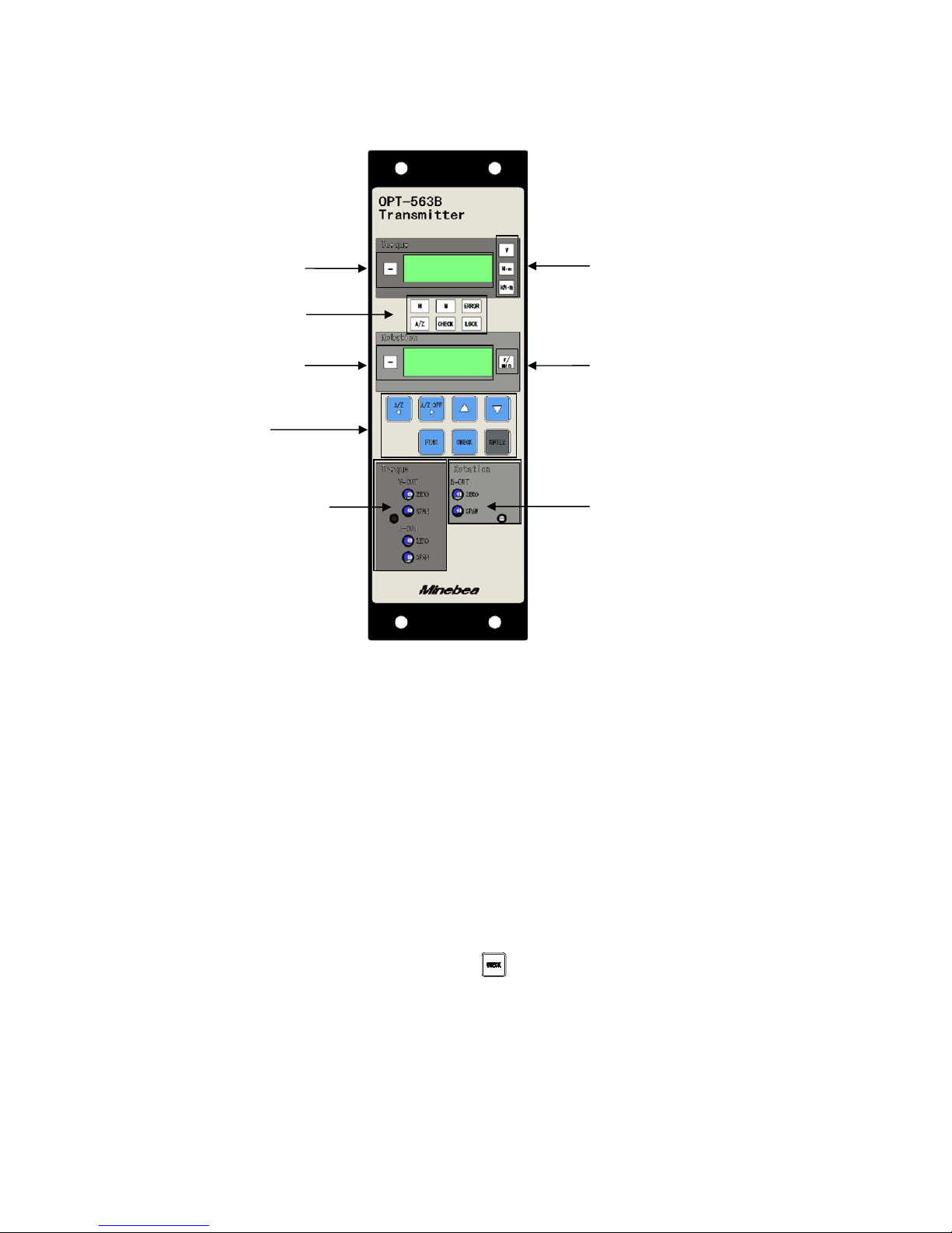
1-1. Front Panel
(1) Torque units display
Displays the measurement units set.
(2) Torque display
Displays the torque reading and [OL] (for over limit).
(3) Status display
Indicates the OPT-563B status.
H : Illuminates when the torque meter light level is normal.
M : Illuminates when the torque meter light level is low.
Note that [M] does not illuminate if used in conjunction with the DBX-001 power
supply box.
A/Z : Illuminates when the A/Z function operates.
CHECK : Illuminates when the key is pressed to turn CHECK on.
LOCK : Illuminates when external control input LOCK to COM1 is short-circuited.
ERROR : Illuminates when an error signal is output.
(4) Rotation speed units display
Displays the rotation speed units.
(4) Rotation speed units
display
(2) Torque display
(1) Torque units display
(3) Status display
(6) ~ (12) Key
switches
(13) Torque analog output
trimmer section
(14) Rotation speed analog
output trimmer section
(5) Rotation speed
display
Page 8

6
(5) Rotation speed display
Displays the rotation speed and [OS] (for overspeed).
(6) key
Turns on the A/Z function. Also moves the setting digit to the left when setting numerical values.
(7) key
Turns off the A/Z function. Also moves the setting digit to the right when setting numerical values.
(8) key
Increments the digit selected when setting numerical values.
(9) key
Decrements the digit selected when setting numerical values.
(10) key
Used to select function mode. Also used to return to measurement mode without entering the value
when setting. Depress for at least 2 seconds to select function mode.
(11) key
Used to turn the CHECK value on or off. Depress for at least 2 seconds to turn on the CHECK value.
(12) key
Used for registering settings.
(13) Torque analog output trimmer section
Torque analog output (VOUT and IOUT) zero point and span point trimmer adjustment (fine
adjustment) section
(14) Rotation speed analog output trimmer section
Rotation speed analog output (ROUT) zero point and span point adjustment (fine adjustment) section
Page 9
7
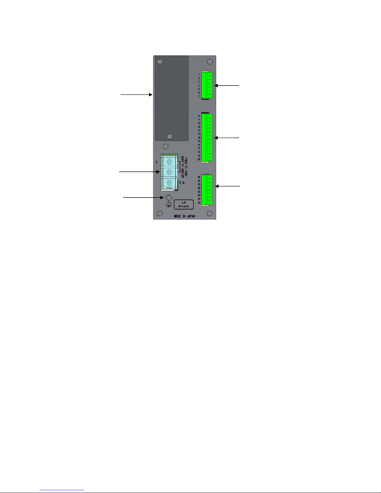
1-2. Rear Panel
(1) Power supply terminal board
Connected to the AC power supply and grounding wire.
(2) Protective ground terminal
Connect this to ground to eliminate noise effects such as static electricity. Do not connect any wires
other than the grounding wire.
This connector is internally linked to F.G. on the power supply terminal board.
(3) External control input/output connector
Used to connect the external control device.
(4) Torque transducer/rotation speed detector connector
Connect the signal cable to the torque transducer/rotation speed detector (MP-9820).
(5) Analog output connector
Connect the signal cable to the analog input device.
(6) Optional part mounting section
One optional part (RS-232C, RS-422/485, PROFIBUS, or CANopen) can be mounted.
(1) Power supply
terminal board
(2) Protective
ground terminal
(6) Optional part
mounting section
(3) External control
input/output connector
(4) Torque transducer/rotation speed
detector connector
(5) Analog output connector
Page 10

8
2. Operating Instructions
This section describes how to operate the equipment using the keys on the front panel.
CAUTION
Stop measuring before operating the keys. There is a risk of malfunctioning if the keys are operated
while measurement is in progress.
Key operations in measurement mode are enabled by depressing for approximately 1 second.
2-1. Key
2-1-1. When Operated in Measurement Mode
This selects function mode and is displayed on the setting display.
Function setting or other modes can be selected in this mode.
2-2. Key
2-2-1. When Operated in Measurement Mode
Pressing this button activates the auto-zero function and zeros the torque reading if the value displayed
on the torque display is 10% or less of the maximum value. [A/Z] is also displayed on the status display.
2-2-2. When Operated in Other Modes
Pressing the key when a setting is displayed causes the flashing digit to move to the left in the
sequence 10
1
, 102, 103, 104. (Note that the range of movement will vary depending on the number of
digits and sign displayed.)
2-3. Key
2-3-1. When Operated in Measurement Mode
This cancels the auto-zero function, and [A/Z] disappears on the status display.
2-3-2. When Operated in Other Modes
Pressing the key when a setting is displayed causes the flashing digit to move to the right in the
sequence 10
4
, 103, 102, 101. (Note that the range of movement will vary depending on the number of
digits and sign displayed.)
2-4. Key
2-4-1. When Operated in Measurement Mode
This has no effect.
Page 11

9
2-4-2. When Operated in Other Modes
Setting increment
Pressing the key when a setting is displayed increments the value in sequence from 0 to 9, and
then back to 0.
Fine adjustment increment
Pressing the key for fine adjustment of the zero point, span point, asymmetry correction,
linearization correction, or analog output increments the corresponding value.
2-5. Key
2-5-1. When Operated in Measurement Mode
This has no effect.
2-5-2. When Operated in Other Modes
Setting decrement
Pressing the key when a setting is displayed decrements the value in sequence from 0 to 1, and
then back to 0.
Fine adjustment decrement
Pressing the key for fine adjustment of the zero point, span point, asymmetry correction,
linearization correction, or analog output decrements the corresponding value.
2-6. Key
2-6-1. When Operated in Measurement Mode
[CHECK] illuminates on the status display, and the value (CHECK value) set in function mode F-20 is
output from the torque analog output (V-OUT/I-OUT). For further details, refer to Section 9-2.
2-6-2. When Operated in Other Modes
This has no effect.
2-7. Key
Pressing the key registers the setting altered within the system.
Page 12

10
3. Calibration
Calibration refers to the process of adjusting the display reading to match the torque acting on the
torque transducer in order to ensure that the electrical signal from the torque transducer is
displayed as an accurate torque figure.
For example, this adjustment ensures that an accurate reading of 1000.0 N·m is given when a
torque of 1,000 N·m acts on the torque transducer.
The equipment must always be calibrated before using for the first time or after replacing a torque
transducer.
When calibrating the equipment before using for the first time, calibrate by entering the numerical
values, referring to the calibration certificate sheet provided when the torque transducer was
purchased.
When calibrating the equipment after replacing a torque transducer, calibrate by entering the
numerical values, referring to the calibration certificate sheet provided with the torque transducer
purchased.
3-1. Settings Required for Calibration
(1) Minimum scale division
The minimum measurement interval. The available settings are [1], [2], [5], and [10].
The value set for [SPAN value/MIN. SCALE DIVISION] will form the display resolution.
(2) SPAN value
The maximum torque value that can be measured by the torque transducer.
(3) ZERO calibration
The setting to be calibrated to ensure that the equipment torque reading is zero when no torque is
applied to the torque transducer (initial torque state). This can be calibrated either using the torque
value (initial torque state) or by entering the torque transducer output value.
(4) SPAN calibration
The setting to be calibrated to ensure that the variations in the electrical signal from the torque
transducer are displayed on the equipment correctly as the torque when a torque is applied to the
torque transducer. This can be calibrated either using the torque value (span torque state) or by
entering the torque transducer output value.
(5) Calibration data selection
The equipment can save up to four sets of calibration data. Select the location for saving the
calibration data by selecting Calibration Data 1 to 4 before calibrating using F-59. If the equipment is
jointly calibrated at Minebea, the calibration data will be stored to [Calibration Data 1].
3-2. Settings to be Altered As Necessary After Calibration
For details of the setting instructions, refer to Instruction Manual EN294-1596*.
(1) Symmetry correction
This function corrects torsional span errors in the clockwise and counter-clockwise directions.
(2) Linearization correction
This function minimizes measuring errors by correcting up to five points, excluding zero and span.
(3) Change polarity
This function inverts the polarity of the torque transducer output.
(4) Decimal place
Sets the decimal place for the torque reading on the equipment.
(5) Units
Adds units to the torque reading on the equipment.
Recalib rate as necessary if the usage environment changes.
The maximum readout resolution for valid performance is 10,000.
In span calibration, use a value of at least 2/3 of the span to minimize calibration errors.
Page 13

11
3-3. Calibration Procedure
3-3-1. Calibration in Measurement Mode
Step 1
Step 2
Step 3
Step 4
Step 5
Step 6
Step 7
Step 8
Step 9
Connect the torque transducer to the equipment.
Turn on and wait for approximately 10 minutes for the torque
transducer and equipment to stabilize.
Select calibration mode.
Select the minimum torque units.
Select the minimum torque units.
Set the maximum torque value that can be measured by the
torque transducer.
Calibrate the zero point with the torque transducer at the initial
torque state or by setting the zero point torque for the torque
transducer.
Calibrate the span point with the span torque acting on the torque
transducer or by setting the span point torque for the torque
transducer.
Calibration is complete. Perform steps 10 onward as described
below where necessary.
Steps 4 to 9 must be carried out in sequence. The calibration results will not be updated if the proced ure is not
completed up to step 9.
The A/Z function is canceled once calibration is completed (up to step 9).
The A/Z function is canceled if step 10, 11, or 12 is performed.
For details of steps 11 to 15, refer to Instruction Manual EN294-1596*.
Section 3-3-3
Minimum scale
division setting
Section 3-3-4
Torque setting
Step 11
Ste
p
12 Step 13
Ste
p
14
Section 3-3-5
Actual torque setting
Section 3-3-7
Span calibration
Section 3-3-6
Zero calibration
Step 15
After turning on powe
r
Calibration mode
selection
End of calibration
Decimal place
setting
Units setting
Symmetry
correction
function
Linearization
correction
function
Polarity change
function
Step 10
Section 3-4
Zero/span fine
adjustment
function
Torque transducer
connection
Page 14

12
3-3-2. Selecting Calibration Mode
Calibration mode can be selected from measurement mode as follows.
appears in the upper part when the key
is depressed for approximately 2 seconds in measurement
mode.
The upper display reads when the key
is pressed.
The upper display reads and
flashes on the lower display, indicating
calibration mode has been selected when the key is
pressed.
(If the equipment has been previously calibrated, the
minimum scale division registered at that time will be
displayed.)
3-3-3. Minimum Scale Division Setting
Set the minimum scale division for torque.
Use the or key to set the required minimum scale
division on the lower display. Select from [1], [2], [5], or [10].
* Enter value (1) on the calibration certificate sheet. (No
decimal point)
For example, if the minimum digit is 100.00 N·m, set to [d-01].
: Selects the minimum scale division.
: Cancels the setting and returns to
measurement mode.
: Registers the value displayed and proceeds
to the next step.
Press the key after setting. (If the equipment has been
previously calibrated, the torque value registered at that time
will be displayed.)
The maximum readout resolution for valid performance is 10,000.
Measurement
mode
To minimum scale
division setting
Registered minimum
scale division
Registered minimum
scale division
Minimum scale
division used
To torque setting
Registered torque
value
Page 15

13
3-3-4. Torque Setting
Set the maximum torque displayed.
Use the keys to change the torque
on the lower display to the required value.
* Enter value (2) on the calibration certificate sheet. (No
decimal point)
For example, if the maximum indication is 100.00 N·m,
set to [10000].
: Alters the value of the digit to be
altered.
: Selects the digit to be altered.
: Cancels the setting and returns to
measurement mode.
: Registers the value displayed and
proceeds to the next step.
Press the key after setting.
New torque value
To actual torque
setting
Registered torque
value
New torque value
Page 16

14
3-3-5. Actual Torque Setting
Set actual torque acting on the torque transducer (or torque transducer output).
When calibrating by entering numerical values, set the same value as set in "3-3-4 Torque Setting".
* Enter value (3) on the calibration certificate sheet. (No decimal point)
For example, if the maximum indication is 100.00 N·m, set to [10000].
Use the keys to change the torque on
the lower display to the required value.
: Alters the value of the digit to be altered.
: Selects the digit to be altered.
: Cancels the setting and returns to
measurement mode.
: Registers the value displayed and
proceeds to the next step.
Press the key after setting.
Actual torque value
or torque meter output
To zero calibration
New torque value
Page 17

15
3-3-6. Zero Calibration
Register the input at the zero point.
To calibrate by entering the torque value for the torque transducer, press the key and then press
the key.
Calibrate zero by entering the zero point torque (frequency) for the torque transducer.
Calibration by entering the torque value for the torque
transducer
Press the key to display in the
lower display, and then press the key to display the
value.
The value displayed will be the output frequency for the
torque transducer at the initial torque state previously
registered.
Set the torque value (frequency) corresponding to the zero
point in 1 Hz intervals.
* Enter the torque calibration value zero frequency
included on the calibration certificate sheet for the torque
transducer.
* Enter value (4) on the calibration certificate sheet. (No
decimal point)
For example, if the torque calibration value (zero) is
9.957 kHz, set to [9957].
: Alters the value of the digit to be altered.
: Selects the digit to be altered.
: Cancels the setting and returns to
measurement mode.
: Registers the value displayed and
proceeds to the next step.
Press the key after setting.
Zero calibration error display
: The display flashes for approximately 2 seconds when the torque transducer
frequency output is less than 9,500 Hz or if the value entered is less than 9,500 Hz.
: The display flashes for approximately 2 seconds when the torque transducer
frequency output exceeds 10,500 Hz or if the value entered exceeds 10,500 Hz.
To span calibration
Hz
Registered torque transducer output
value
Hz
Set torque transducer output value
Page 18

16
3-3-7. Span Calibration
Register the input at the span point.
To calibrate by entering the torque value for the torque transducer, press the key and then press
the key.
Calibrate span by entering the span point torque (frequency) for the torque transducer.
Calibration by entering the torque value for the torque
transducer
Press the key to display in the
lower display, and then press the key to display
. The value displayed will be the output
frequency for the torque transducer at the span point
previously registered. Set the torque value (frequency)
corresponding to the span point in 1 Hz intervals.
* Enter the torque calibration value span frequency
included on the calibration certificate sheet for the torque
transducer.
* Enter value (5) on the calibration certificate sheet. (No
decimal point)
For example, if the torque calibration value (span) is
14.913 kHz, set to [14913].
: Alters the value of the digit to be altered.
: Selects the digit to be altered.
: Cancels the setting and returns to
measurement mode.
: Registers the value displayed and
proceeds to the next step.
Press the key after setting.
Span calibration error display
: The display flashes for approximately 2 seconds when [span point torque transducer
output frequency or span point torque transducer value entered] - [zero point torque
transducer output frequency or zero point torque transducer value entered] ≤ 0 or when
the torque transducer output frequency is less than 14,500 Hz or if the value entered is
less than 14,500 Hz.
: The display flashes for approximately 2 seconds when the torque transducer output
frequency exceeds 15,500 Hz or if the value entered exceeds 15,500 Hz.
In span calibration, use a torque value of at least 2/3 of the display torque to minimize calibration
errors.
Hz
Registered torque transducer
output value
Hz
Set torque transducer output value
Page 19

17
3-3-8. Calibration End
Displays after span calibration ends.
Press the key to exit calibration mode.
The system switches to measurement mode and the data set is registered.
Th e calib ration values (zero point and span) will not be entered unless the procedure is performe d in sequence
up to this step.
Calibration can be performed only in the counter-clockwise torsional direction.
The A/Z function is canceled once calibration is completed.
Measurement
mode
Page 20

18
3-4. Zero/Span Fine Adjustment Function
This function fine-adjusts the zero point and span point if there are discrepancies between the actual
torque and the reading displayed.
3-4-1. Selecting Zero Point Fine-adjustment Mode
Zero point fine-adjustment mode can be selected from measurement mode as follows.
appears in the upper part when the key is
depressed for approximately 2 seconds in measurement mode.
The upper display reads when the key is
pressed twice.
The upper display reads and the reading on the
lower display flashes, indicating zero point fine-adjustment mode
has been selected when the key is pressed. The lower display
displays the torque value currently entered. Set the torque
transducer to the initial torque state, and adjust the display to
[ZERO].
: Increments the torque.
Hold down the key to increment the torque continuously.
: Decrements the torque.
Hold down the key to decrement the torque continuously.
: Cancels the setting and returns to measurement mode.
: Registers the value displayed and proceeds to the next
step.
Press the key after setting.
is displayed after zero point fine-adjustment.
Press the key to exit zero point fine-adjustment mode. The
system switches to measurement mode and the data set is
registered.
Measurement
mode
Current
torque value
(twice)
Measurement
mode
Page 21

19
3-4-2. Selecting Span Point Fine-adjustment Mode
Span point fine-adjustment mode can be selected from measurement mode as follows.
.
appears in the upper part when the key
is depressed for approximately 2 seconds in measurement
mode.
The upper display reads when the key
is pressed three times.
The upper display reads and the reading on
the lower display flashes, indicating span point fine-adjustment
mode has been selected when the key is pressed. The
lower display displays the torque value currently entered. Apply
an actual torque to the torque transducer, and adjust the
display to [actual torque value].
: Increments the torque.
Hold down the key to increment the torque
continuously.
: Decrements the torque.
Hold down the key to decrement the torque
continuously.
: Cancels the setting and returns to measurement
mode.
: Registers the value displayed and proceeds to the
next step.
Press the key after setting.
is displayed after span point fine-adjustment.
Press the key to exit span point fine-adjustment mode.
The system switches to measurement mode and the data set is
registered.
The change polarity setting will be temporarily canceled for zero/span fine-adjustment. (Restored after
adjustment)
The A/Z function is canceled once the zero/span fine-adjustment function ends.
Measurement
mode
Current torque
value
(3 times)
Measurement
mode
Page 22

20
4. Function Mode
4-1. Selecting Function Mode
Function mode can be selected from measurement mode as follows.
appears in the upper part when the
key is depressed for approximately 2 seconds in
measurement mode.
The upper display reads when the
key is pressed.
Use the keys to select the required
function number on the upper display.
: Alters the value of the digit to be altered.
: Selects the digit to be altered.
: Cancels the setting and returns to
measurement mode.
: Registers the value displayed and
proceeds to the next step.
Press the key after setting.
The lower display changes to display the function
details.
Use the keys to select the required
function number on the lower display.
The upper display reads when the
key is pressed, indicating that function registration
is complete.
Press the key to exit function mode and return to
measurement mode.
Measurement mode
Value set
Value registered
To measurement mode
Value set
Page 23

21
4-2. Function List
Function No. Item
Setting
value
Details
F-01 Decimal place
●0 No decimal point
1 1000.0
2 100.00
3 10.000
4 1.0000
F-02 Torque display units
●0 N·m
1 kN·m
2 V
F-04 Display cycles
0 4 cycles/s
●1 20 cycles/s
F-05 Torque analog filter
0 1 Hz
1 10 Hz
2 30 Hz
3 50 Hz
4 100 Hz
5 300 Hz
6 500 Hz
●7 1 kHz
F-06 Torque digital filter
00~88
No. of moving-average samples = 2
m+2n
m: 101 setting, n: 100 setting
●00
F-07 Rotation speed analog filter
0 1 Hz
●1 10 Hz
F-08 Rotation speed digital filter
00~88
No. of moving-average samples = 2
m+2n
m: 101 setting, n: 100 setting
●00
F-09
Torque stabilization filter
No. of averaging
0 No. of moving-average samples: 1
1 No. of moving-average samples: 2
2 No. of moving-average samples: 4
3 No. of moving-average samples: 8
4 No. of moving-average samples: 10
5 No. of moving-average samples: 12
●6 No. of moving-average samples: 14
7 No. of moving-average samples: 16
8 No. of moving-average samples: 32
F-10
Torque stabilization filter
Time width setting
000~999
Unit: 10 ms
000: Torque stabilization filter off
●000
F-11
Torque stabilization filter
Data width setting
00~99
Unit: DIGIT
00: Torque stabilization filter off
●20
Page 24

22
Function No. Item
Setting
value
Details
F-15
Rotation speed stabilization
filter
No. of averaging
0 No. of moving-average samples: 1
1 No. of moving-average samples: 2
2 No. of moving-average samples: 4
3 No. of moving-average samples: 8
4 No. of moving-average samples: 10
5 No. of moving-average samples: 12
●6 No. of moving-average samples: 14
7 No. of moving-average samples: 16
8 No. of moving-average samples: 32
F-16
Rotation speed stabilization
filter
Time width setting
000~999
Unit: 10 ms
000: Rotation speed stabilization filter off
●000
F-17
Rotation speed stabilization
filter
Data width setting
00~99
Unit: DIGIT
00: Rotation speed stabilization filter off
●20
F-18 Key lock
0000
~1111
●0000
0: Off
1: On
10
0
digit:
10
1
digit:
10
2
digit:
10
3
digit:
F-19 Polarity change
●0
Torque in counter-clockwise direction is
positive.
1 Torque in clockwise direction is positive.
F-20 CHECK value
0~20
Refer to Section 9-2-3.
●16
F-21
Torque analog output
Max. display value
1~99 999
Unit: DIGIT
●10 000
F-22
Rotation speed analog output
Max. display value
1~27 500
Unit: DIGIT
●25 000
F-23 Rotation direction polarity
● 0 +
1 -
F-24
Rotation detection input signal
format
● 0 Off
1 Measured using 2 rotation detectors
2
Measured using 1 rotation detector.
Rotation direction detected using external
input signal
3
Measured using 1 rotation detector.
Rotation direction cannot be detected.
Page 25

23
Function No. Item
Setting
value
Details
F-25 No. of rotation detection gears
●0 120
1 240
2 360
F-26
Selecting A/Z data save
destination
●0 RAM
1 EEPROM
F-30 RS-232C operating mode
●0 Command mode
1 Stream mode
F-31 RS-232C stream output target
●0 Torque display data
1 Input torque A/D data
2 Rotation speed display data
3 Frequency data
F-32
RS-232C/RS-422/RS-485
Baud rate
0 1,200 bps
1 2,400 bps
2 4,800 bps
●3 9,600 bps
4 19,200 bps
5 38,400 bps
6 57,600 bps
7 115,200 bps
F-33
RS-232C/RS-422/RS-485
Data bit length
●0 7 bit
1 8 bit
F-34
RS-232C/RS-422/RS-485
Parity bit
0 None
●1 Odd
2 Even
F-35
RS-232C/RS-422/RS-485
Stop bit
●0 1 bit
1 2 bit
F-36
RS-232C/RS-422/RS-485
Terminator
0 CR
●1
CR+LF
F-37
RS-232C/RS-422/RS-485
Decimal point
●0 No
1 Yes
F-38 RS-422/485 address
00~31
●00
F-39 RS-422/485 selection
●0 RS-422
1 RS-485
F-40 RS-485 data delay time
000~999
Unit: 10 ms
Can be set in range 0~9.99 s.
●001
Page 26

24
Function No. Item
Setting
value
Details
F-41
PROFIBUS
Station No.
000~125
●000
F-42
CANopen
Node ID
001~127
●001
F-43
CANopen
Baud rate
0 10 kbps
1 20 kbps
2 50 kbps
3 100 kbps
4 125 kbps
5 250 kbps
6 500 kbps
7 800 kbps
●8 1 Mbps
F-45
CANopen
PDO output frequency
0~100
0: Off
Unit: 1 ms
●100
F-50 Maintenance 1 00000 0~99 999 (Do not use)
F-51 Maintenance 2 00000 0~99 999 (Do not use)
F-55 Calibration prohibited 0000
0: Calibration permitted
1: Calibration prohibited
10
0
digit: Calibration data 1
10
1
digit: Calibration data 2
10
2
digit: Calibration data 3
10
3
digit: Calibration data 4
F-56 Symmetry correction clear 0
Clear data corrected using symmetry
correction function.
F-57
Clearing counter-clockwise
linearization correction
0
Clear data corrected using linearization
correction function. (Counter-clockwise
direction)
F-58
Clearing clockwise linearization
correction
0
Clear data corrected using linearization
correction function. (Clockwise direction)
F-59 Calibration data selection
●0 Calibration data 1
1 Calibration data 2
2 Calibration data 3
3 Calibration data 4
F-60 Calibration 1 Increment 1 Datum value (initial value)
F-61
Calibration 1 Maximum display
value
10000 Datum value (initial value)
F-62
Calibration 1 Actual torque
value
10000 Datum value (initial value)
F-63 Calibration 1 ZERO A/D 0x1FFFF Datum value (initial value)
F-64 Calibration 1 +SPAN A/D 0x3AAAA Datum value (initial value)
F-65 Calibration 1 -SPAN A/D 0x5555 Datum value (initial value)
F-66
Calibration 1 ZERO frequency
conversion value
10000 Datum value (initial value)
F-67
Calibration 1 +SPAN frequency
conversion value
15000 Datum value (initial value)
F-68
Calibration 1 -SPAN frequency
conversion value
5000 Datum value (initial value)
Page 27

25
Function No. Item
Setting
value
Details
F-70 Calibration 2 Increment 1 Datum value (initial value)
F-71
Calibration 2 Maximum display
value
10000 Datum value (initial value)
F-72
Calibration 2 Actual torque
value
10000 Datum value (initial value)
F-73 Calibration 2 ZERO A/D 0x1FFFF Datum value (initial value)
F-74 Calibration 2 +SPAN A/D 0x3AAAA Datum value (initial value)
F-75 Calibration 2 -SPAN A/D 0x5555 Datum value (initial value)
F-76
Calibration 2 ZERO frequency
conversion value
10000 Datum value (initial value)
F-77
Calibration 2 +SPAN frequency
conversion value
15000 Datum value (initial value)
F-78
Calibration 2 -SPAN frequency
conversion value
5000 Datum value (initial value)
F-80 Calibration 3 Increment 1 Datum value (initial value)
F-81
Calibration 3 Maximum display
value
10000 Datum value (initial value)
F-82
Calibration 3 Actual torque
value
10000 Datum value (initial value)
F-83 Calibration 3 ZERO A/D 0x1FFFF Datum value (initial value)
F-84 Calibration 3 +SPAN A/D 0x3AAAA Datum value (initial value)
F-85 Calibration 3 -SPAN A/D 0x5555 Datum value (initial value)
F-86
Calibration 3 ZERO frequency
conversion value
10000 Datum value (initial value)
F-87
Calibration 3 +SPAN frequency
conversion value
15000 Datum value (initial value)
F-88
Calibration 3 -SPAN frequency
conversion value
5000 Datum value (initial value)
F-90 Calibration 4 Increment 1 Datum value (initial value)
F-91
Calibration 4 Maximum display
value
10000 Datum value (initial value)
F-92
Calibration 4 Actual torque
value
10000 Datum value (initial value)
F-93 Calibration 4 ZERO A/D 0x1FFFF Datum value (initial value)
F-94 Calibration 4 +SPAN A/D 0x3AAAA Datum value (initial value)
F-95 Calibration 4 -SPAN A/D 0x5555 Datum value (initial value)
F-96
Calibration 4 ZERO frequency
conversion value
10000 Datum value (initial value)
F-97
Calibration 4 +SPAN frequency
conversion value
15000 Datum value (initial value)
F-98
Calibration 4 -SPAN frequency
conversion value
5000 Datum value (initial value)
F-99 Memory clear -
Returns function settings to default
settings.
Page 28

26
SAMPLE
(1)
(2)(3)
(4)
(5)
Page 29

.
Page 30

D The contents of this manual may subject to change without notice.
HEAD QUARTER : MINEBEA CO., LTD.
4106−73 Miyota, Miyota−machi, Kitasakugun, Nagano−ken 389−0293, Japan
0267−32−2200 .0267−31−1350
Measuring Components Business Unit
FUJISAWA PLANT 1−1−1, Katase, Fujisawa−shi Kanagawa−ken, 251−8531 Japan
0466−22−7152 .0466−22−1701
KARUIZAWA PLANT 4106−73 Miyota, Miyota−machi, Kitasakugun, Nagano−ken 389−0293, Japan
0267−31−1309 .0267−31−1350
HOMEPAGE ADDRESS http://www.minebea−mcd.com
 Loading...